Advertisement
Quick Links
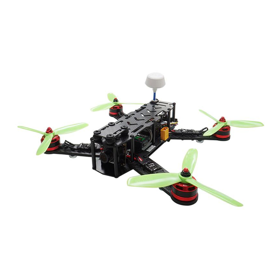
ARRIS X-Speed 250B Assembling Manual
Thank you for purchasing the ARRIS X-Speed 250B FPV Racing drone. Be sure to read through the entire manual before starting your build. If you bought the ARRIS
X-Speed 250B frame, or super combo version, this manual will provide you the necessary information to complete the building with a minimum amount of effort.
Advertisement

Related Manuals for Arris X-Speed 250B

Summary of Contents for Arris X-Speed 250B
- Page 1 ARRIS X-Speed 250B Assembling Manual Thank you for purchasing the ARRIS X-Speed 250B FPV Racing drone. Be sure to read through the entire manual before starting your build. If you bought the ARRIS X-Speed 250B frame, or super combo version, this manual will provide you the necessary information to complete the building with a minimum amount of effort.
- Page 2 1. What includes in the package? Screw Bag x 1 PDB Board x 1 Lower Plate x 1 Battery Plate x 1 Arms Bag x 1 Accessory x 1 Explosive Diagram x 1...
- Page 3 2. Suggested tools for assembling. 1.5mm screw driver x 1 2.0mm screw driver x 1 M2.5 Hexagon socket Scissors x 1 tweezers x 1 M2.5 socket wrench x 1 3M tape and cable tie...
- Page 4 3. Install the rubber landing gear on the arms according to the following pictures. Make sure to have the face with arrow mark on the top.
- Page 5 4. Solder the brushless ESC and motor. Take ARRIS 2205 2300KV motor and ARRIS 20A ESC as an example. Before going to the next step, we need to define two terms. “CW” means the motor rotation is clockwise. “CCW” means the motor rotation is counter-clockwise.
- Page 6 5. Install the soldered motor and ESC on the motor arms with M3*7 screws (here all the screws need to add screw glue). After all the motors have been installed correctly, stick a double-sided adhesive tape to the position of the ESC, then place the ESC on it.
- Page 7 6. Solder the wires of video TX and camera on the PDB, cut off spare wires and keep them in store for future use.
- Page 8 7. Install the bottom plate. 8. Install the motor arms. Here we need 8 x M3*12 screws, 4 x M3*35 columns and 4 x M3 nuts. All the screws need to be added with screw glue.
- Page 10 This is what it looks like when assembled well. 9. Cut off spare wires, then solder them on the PDB. (Keep these wires in store for future use)
- Page 12 10. Solder the ESC output wire and power cable of the flight controller. Then make some modification for those spare wires cut off in previous steps. Check following pictures: 11. Install the left aluminum column. Here we need 2 x M3*35 screws and 2 x M3*7*4 white nylon spaces.
- Page 13 12. Install the M3*40 aluminum column. Her we need 4 x M3*40 column and 4 x M3*8 screws.
- Page 14 13. Install the flight controller. Here we take F3 flight controller as an example: 13.1. solder the pin according to the following picture, then install the outer case.
- Page 15 13.2. Stick the F3 flight controller on the frame with 3M adhesive tape. Make sure to have the flight controller pasted in horizontal position, no little tilt or the flying performance might be heavily influenced. Then plug in the ESC wire, pay attention to the “+” “-” direction.
- Page 16 13.3. Solder the voltage-detective cable of the flight controller. Take the connector that comes with flight controller out, plug one side to VBAT connection, solder another side to the PDB. Red is “+”, blade is “-”, don`t get mixed. 13.4. Install the buzzer. The buzzer is mainly used to offer low voltage alarm and search for aircrafts. Pick out the connector that comes with the flight controller, plug one side to the BUZZ connection of flight controller, solder another side on the buzzer.
- Page 17 14. Install the camera according to the following picture.
- Page 18 15. Install receiver. Here we use R9D receiver, which supports SBUS. Paste the receiver on the absorbing plate with 3M adhesive tape. Plug one side of the receiver to SBUS port, and another side to UART3 port of flight controller.
- Page 19 16. Install video TX and antenna. Pick our required accessories, stick them together, then paste them to the bottom plate with 3M adhesive tape.
- Page 20 17. Assemble the upper plate according to the following picture.
- Page 21 18. Install the well-assembled upper plate on the frame. All the screws need to be added with screw glue. The while rubber is used to fix the antenna, so it needs to be cut off.
- Page 23 19. Insert the camera installing plate into damper balls.
- Page 24 Now, the assembling work is finished. You need to connect the F3 flight controller to your computer and install the Clearnflight software to get the perfect PID of your drone. Please check another manual for how to use F3 flight controller. If there is any problem in using this product, please feel free to contact us at service@hobby-wing.com support@hobby-wing.com...
Need help?
Do you have a question about the X-Speed 250B and is the answer not in the manual?
Questions and answers