Table of Contents
Advertisement
Advertisement
Table of Contents

Related Manuals for Ytc YT-2500 SERIES


Summary of Contents for Ytc YT-2500 SERIES
- Page 1 SMART POSITIONER PRODUCT MANUAL YT-2500 / 2550 / 2501 SERIES VERSION 1.04...
-
Page 2: Table Of Contents
Smart Positioner YT-2500 / 2550 / 2501 Series Product manual Contents Introduction ........................... 5 General Information for the users ................... 5 Manufacturer Warranty ......................5 Explosion Proof Warning (Only for Intrinsic safety type positioners) ........6 Product Description ........................7 General ............................ - Page 3 Smart Positioner YT-2500 / 2550 / 2501 Series Product manual Connection – Power ........................30 Safety ............................ 30 Connection ..........................30 Ground ..........................31 Adjustments ..........................32 Limit Switch Adjustment ......................32 Variable Orifice Adjustment ....................33 Optional Sub-PCB Installment ....................34 Installation steps ........................
- Page 4 Smart Positioner YT-2500 / 2550 / 2501 Series Product manual View Mode (VIEW) ........................ 48 Error and Warning Code ......................50 Error code ..........................50 Warning code ........................51 Main Software Map ........................52 Ver. 1.04...
-
Page 5: Introduction
Smart Positioner YT-2500 / 2550 / 2501 Series Product manual 1. Introduction General Information for the users Thank you for purchasing Young Tech Co., Ltd products. Each product has been fully inspected after its production to offer you the highest quality and reliable performance. Please read the product manual carefully prior to installing and commission the product. -
Page 6: Explosion Proof Warning (Only For Intrinsic Safety Type Positioners)
Smart Positioner YT-2500 / 2550 / 2501 Series Product manual Explosion Proof Warning (Only for Intrinsic safety type positioners) Please ensure the unit is being used and installed in conformity with local, regional, and national explosion proof within the proper safety barrier environment. ... -
Page 7: Product Description
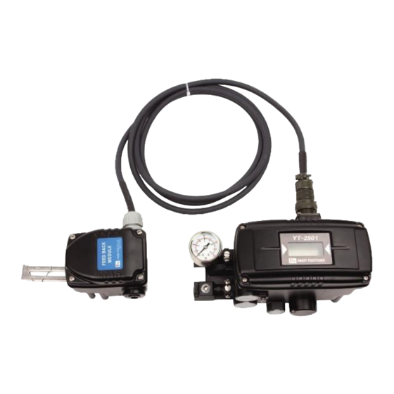
Smart Positioner YT-2500 / 2550 / 2501 Series Product manual 2. Product Description General YT-2500 / 2550 / 2501 series Smart Valve Positioner accurately controls valve stroke in response to an input signal of 4~20mA from the controller. Built-in micro-processor optimizes the positioner’s performance and provides unique functions such as Auto- Calibration, PD Control and HART Protocol Communications. -
Page 8: Label Description
Smart Positioner YT-2500 / 2550 / 2501 Series Product manual Label Description Fig. 2-1: YT-2500 / 2501 None explosion type Fig. 2-2: YT-2550 None explosion type Fig. 2-3: YT-2500 / 2501 Intrinsic safety type Fig. 2-4: YT-2550 Intrinsic safety type Fig. -
Page 9: Product Number
Smart Positioner YT-2500 / 2550 / 2501 Series Product manual Product Number 2.4.1 YT-2500 / 2550 series follows suffix symbols as follows. YT-2500 / 2550 1 Linear Motion Type Rotary Single Acting type Double Non-Explosion Explosion Proof Ex ia IIC T5/T6 10 ~ 40 mm Lever Type 20 ~ 70 mm... -
Page 10: Yt-2501 Series Follows Suffix Symbols As Follows
Smart Positioner YT-2500 / 2550 / 2501 Series Product manual 2.4.2 YT-2501 series follows suffix symbols as follows. YT-2501 1 Linear Motion Type Rotary Single Acting type Double Non-Explosion Explosion Proof Ex ia IIC T5/T6 10 ~ 40 mm Lever Type 20 ~ 70 mm Linear 50 ~ 100 mm... -
Page 11: Product Specification
Smart Positioner YT-2500 / 2550 / 2501 Series Product manual Product Specification 2.5.1 YT-2500 / 2550 Specification Model YT-2500 YT-2550 Housing Material Aluminum Stainless steel 316 Motion Type Linear Rotary Linear Rotary Acting Type Single / Double Standard 4~20mA DC Input Signal 9~32V DC, Max Current Draw 18mA Minimum Current Signal... -
Page 12: Yt-2501 Specification
Smart Positioner YT-2500 / 2550 / 2501 Series Product manual 2.5.2 YT-2501 Specification Model YT-2501 Housing Material Aluminum Motion Type Linear Rotary Acting Type Single / Double Standard 4~20mA DC Input Signal 9~32V DC, Max Current Draw 18mA Minimum Current Signal 3.5mA(Standard), 3.8mA(Hart Included) Supply Pressure 0.14 ~ 0.7 MPa (1.4 ~ 7 bar) -
Page 13: Certifications
Smart Positioner YT-2500 / 2550 / 2501 Series Product manual Certifications KC (Korea) Type : Intrinsic safety Rating : Ex ia IIC T5/T6 Certification No. : 11-KB2BO-0163X(YT-2500) 10-KB2BO-0005X(YT-2500+LS(Dry contact)) 14-KB2BO-0336X(YT-2500+LS(Non-contact)) 11-KB2BO-0165X(YT-2550) 11-KB2BO-0166X(YT-2550+LS(Dry contact)) 14-KB2BO-0337X(YT-2550+LS(Non-contact)) 11-KB2BO-0164X(YT-2501) Ambient temperature : -40 ~ +60℃ (T5/T100℃), -40 ~ +40℃ (T6/T85℃) ... -
Page 14: Parts And Assembly
Smart Positioner YT-2500 / 2550 / 2501 Series Product manual Parts and Assembly Fig. 2-7: YT-2500 / 2550 series exploded view 1. Base Cover 6. Potentiometer 2. Option PCB 7. Main shaft 3. Main PCB 8. Base body 4. Pressure Gauge 9. - Page 15 Smart Positioner YT-2500 / 2550 / 2501 Series Product manual Positioner Rotary Sensor Linear Sensor Fig. 2-8: YT-2501 exploded view 1. Base cover of Feedback sensor 10. Base cover of Positioner 2. Terminal of Feedback sensor 11. PCB of Positioner 3.
-
Page 16: Product Dimension
Smart Positioner YT-2500 / 2550 / 2501 Series Product manual Product Dimension 2.8.1 YT-2500 Fig. 2-9: YT-2500L Fig. 2-10: YT-2500R (Fork Lever Type) Fig. 2-11: YT-2500R (Namur Type) Fig. 2-12: YT-2500R (L/S Option) Ver. 1.04... -
Page 17: Yt-2550
Smart Positioner YT-2500 / 2550 / 2501 Series Product manual 2.8.2 YT-2550 Fig. 2-13: YT-2550L Fig. 2-14: YT-2550R 2.8.3 YT-2501 Fig. 2-16: Rotary Feedback Sensor Fig. 2-15: Linear Feedback Sensor Fig. 2-17: YT-2501 Positioner Ver. 1.04... -
Page 18: Installation
Smart Positioner YT-2500 / 2550 / 2501 Series Product manual 3. Installation Safety When installing a positioner, please ensure to read and follow safety instructions. Any input or supply pressures to valve, actuator, and / or to other related devices must be turned off. -
Page 19: Safety
Smart Positioner YT-2500 / 2550 / 2501 Series Product manual 3.3.1 Safety Proper bracket must be made in order to adapt the positioner on the actuator yoke. Please consider following important points when a bracket is being designed. Positioner’s feedback lever must be vertical to the valve stem at 50% of the valve stroke. ... - Page 20 Smart Positioner YT-2500 / 2550 / 2501 Series Product manual Fig. 3-5: Supplying proper regulated air to the actuator to position the valve at 50% 5. Insert the connection bar between the feedback lever and lever spring. The connection bar must be located upward from the spring lever as shown below left figure. If it is located downward from the spring lever as shown below right figure, the connection bar or the spring lever will be worn out quickly because of excessive strong tension.
- Page 21 To adjust, move the bracket, the connection bar or both. Stroke : 30mm Stroke : 70mm Fig. 3-8: Feedback lever and location of the connection bar ※ The effective linear lever angle of YT-2500 series is 30 degree. Ver. 1.04...
- Page 22 Smart Positioner YT-2500 / 2550 / 2501 Series Product manual 8. After installing the positioner, operate the valve from 0% to 100% stroke by using direct air to the actuator. On both 0% and 100%, the feedback lever should not touch the lever stopper, which is located on the backside of the positioner.
-
Page 23: Rotary Positioner Installation
Smart Positioner YT-2500 / 2550 / 2501 Series Product manual Rotary positioner Installation Rotary positioner should be installed on rotary motion valve such as ball or butterfly type which uses rack and pinion, scotch yoke or other type of actuators which its stem rotates 90 degrees. -
Page 24: Rotary Bracket Information (Only Yt-2500 / 2550)
Smart Positioner YT-2500 / 2550 / 2501 Series Product manual 3.4.3 Rotary Bracket information (Only YT-2500 / 2550) Standard bracket (included with the positioner) contains two components. The bracket is designed to fit onto the actuator with 20mm, 30mm and 50mm stem height (H) according to VDI/VDE 3845 standard. -
Page 25: Rotary Positioner Installation Steps
Smart Positioner YT-2500 / 2550 / 2501 Series Product manual 3.4.4 Rotary positioner Installation Steps 1. Please check the actuator’s stem height and adjust the brackets by referring to the above bracket table. 2. Attached the brackets onto the actuator. It is recommended to use spring washer so the bolts will not be loosen from vibration. - Page 26 Smart Positioner YT-2500 / 2550 / 2501 Series Product manual 6. Attach the positioner to the bracket. <Only fork lever type of YT-2500 / 2550: Fix the clamping pin (5mm Dia.) into the fork lever slot and insert center pin (2mm Dia.) of the main shaft of the positioner into the hole of center of the fork lever.
-
Page 27: Connection - Air
Smart Positioner YT-2500 / 2550 / 2501 Series Product manual 4. Connection - Air Safety Supply pressure should be clean and dry air – avoiding moisture, oil or dust. Always recommended to use air filter regulator (i.e. YT-200 series). ... -
Page 28: Connection - Piping With Actuator
Smart Positioner YT-2500 / 2550 / 2501 Series Product manual Connection – Piping with actuator 4.4.1 Single acting actuator Singe acting type positioner is set to use only OUT1 port. OUT1 port of positioner should be connected with supply port of actuator when using spring return actuator of single acting type. Fig. -
Page 29: Double Acting Actuator
Smart Positioner YT-2500 / 2550 / 2501 Series Product manual 4.4.2 Double acting actuator Double acting type positioner is set to use OUT1 and OUT2 port. As input signal increases, the supply pressure will be supplied through OUT1 port. Fig. 4-5: Double acting linear actuator (YT-2500 / 2550) Fig. -
Page 30: Connection - Power
Smart Positioner YT-2500 / 2550 / 2501 Series Product manual 5. Connection – Power Safety Before connecting terminal, ensure that the power is off completely. Please use ring-type rug to protect against vibration or any other external impact. ... -
Page 31: Ground
Smart Positioner YT-2500 / 2550 / 2501 Series Product manual Fig. 5-2: Mechanical Switch Terminal (Only YT-2500 / 2550) Fig. 5-3: Proximity Sensor Switch Terminal (Only YT-2500 / 2550) Ground 1. Ground must be done before operating the positioner. 2. Open base cover and there is an internal ground “F.G” on the left hand. An external ground bolt is located next to the conduit entry. -
Page 32: Adjustments
Smart Positioner YT-2500 / 2550 / 2501 Series Product manual 6. Adjustments Limit Switch Adjustment YT-2500 / 2550 can have limit switch option. If user wants to adjust the sensing position, please loosen bolts and adjust cam. Fig. 6-1: Mechanical Type Fig. -
Page 33: Variable Orifice Adjustment
Smart Positioner YT-2500 / 2550 / 2501 Series Product manual Variable Orifice Adjustment Hunting can be occurred when the actuator’s volume is too small. In order to prevent hunting, orifice can be adjusted. By adjusting the orifice, the flow rate of the supply pressure to actuator can be adjusted. -
Page 34: Optional Sub-Pcb Installment
Smart Positioner YT-2500 / 2550 / 2501 Series Product manual 7. Optional Sub-PCB Installment By adding sub-PCB, the positioner can have additional functions. There are 3 types of sub- PCB. Hart Only Ptm Only Ptm+Hart Fig. 7-1: Types of Sub-PCB When purchasing option sub-PCBs separately, 4 Bolts and 2 supports (3 at Limit switch internal option) are supplied together with sub-PCB. -
Page 35: Auto Calibration And Pcb Operation
Smart Positioner YT-2500 / 2550 / 2501 Series Product manual 8. Auto Calibration and PCB Operation Warning Following process will operate valve and actuator. Before proceeding with any Auto Calibration, please separate valve from the entire system by using bypass valve, so Auto Calibration will not affect entire valve process. -
Page 36: Run Mode (Run)
Smart Positioner YT-2500 / 2550 / 2501 Series Product manual Run Mode (RUN) After power connection to the positioner, Run Mode will be appeared on positioner’s LCD screen in about 4 seconds. “RUN” indicates that the positioner adjusts the valve stroke according to the receiving signal. -
Page 37: Auto1 Calibration (Auto1)
Smart Positioner YT-2500 / 2550 / 2501 Series Product manual 8.4.1 AUTO1 Calibration (AUTO1) AUTO1 changes only zero and end points; however other parameters(P, D etc.) will not be adjusted. It is recommended to perform AUTO1 when the positioner has been set by the valve manufacturer already, and the field user wants to re-calibrate the positioner. -
Page 38: Manual Mode (Manual)
Smart Positioner YT-2500 / 2550 / 2501 Series Product manual Manual Mode (MANUAL) Manual mode is used to maneuver valve stem manually. In Manual mode, the positioner does not control the valve by the signal received from outside, but it could be controlled to move up and down by pressing <UP>... -
Page 39: P1 Value (Kp1)
Smart Positioner YT-2500 / 2550 / 2501 Series Product manual 8.6.2 P1 Value (KP1) P value indicates the ratio of the compensation signal based on the percentage of error allowance. As the value increase, the positioner finds the target point quickly, but it is more likely to have hunting. -
Page 40: Pt1 (Pt1) And Pt2 (Pt2) Values
Smart Positioner YT-2500 / 2550 / 2501 Series Product manual 8.6.6 PT1 (PT1) and PT2 (PT2) Values PT value indicates the minimum time duration(unit: 0.1mSec) of internal signal controlling pilot valve. PT1 is for increased input signal, and PT2 is for decreased input signal’s PT values. -
Page 41: Hand Calibration Mode (Hand Cal)
Smart Positioner YT-2500 / 2550 / 2501 Series Product manual Hand Calibration Mode (HAND CAL) Manual Calibration mode is used when zero-point and end-point require re-adjustment to use partial range of total strokes after Auto Calibration has been performed. Below are the list of features which could be set from Hand CAL mode. 1) Zero-Point (PV_ZERO) and End-Point (PV_END) for Valves 2) Zero-Point (TR_ZERO) and End-Point (TR_END) for Transmitter 3) End-Point Ratio for Valve (PE TRIM) -
Page 42: Zero-Point (Tr_Zero) And End-Point (Tr_End) For Transmitter
Smart Positioner YT-2500 / 2550 / 2501 Series Product manual 8.7.2 Zero-Point (TR_ZERO) and End-Point (TR_END) for Transmitter TR_ZERO adjusts the zero point of the transmitter (4mA feedback), and TR_END adjusts the end point of the transmitter (20mA feedback). This is used when output signal becomes unstable and requires re-adjustment or when feedback output signal and actual stroke need to be used differently. -
Page 43: End-Point Ratio For Valve (Pe Trim)
Smart Positioner YT-2500 / 2550 / 2501 Series Product manual 8.7.3 End-Point Ratio for Valve (PE TRIM) When reverse acting operating is used, End-Point can be adjusted within 10% of total valve stroke, without adjusting valve’s zero point. <UP>/<DOWN> <ENTER> <ENTER>... -
Page 44: Valve Mode (Valve)
Smart Positioner YT-2500 / 2550 / 2501 Series Product manual Valve Mode (VALVE) Valve mode offers useful and various function settings for operating the control valve. Below are the list of functions which could be set from Valve mode. Acting Adjustment (ACT RA / dA) Characteristic Adjustment (CHAR) User Characteristics (USER SET) Tight Shut Open (TSHUT OP) -
Page 45: Valve Flow Characteristic Adjustment (Char)
Smart Positioner YT-2500 / 2550 / 2501 Series Product manual 8.8.2 Valve flow Characteristic Adjustment (CHAR) The valve flow characteristic can be set on the field’s There are 4 types of characteristics – requirement. linear (LIN), user setting (USR), quick open (QO), and equal percentage (EQ). -
Page 46: Tight Shut Open (Tshut Op)
Smart Positioner YT-2500 / 2550 / 2501 Series Product manual 8.8.4 Tight Shut Open (TSHUT OP) Tight shut open shows the current value in percentage (%). Input current of 4mA is 0%, 20mA is 100%. If temporary Tight shut open value (≤100%) is set and input current value is above the set % value, the valve’s position is immediately moved to 100%. -
Page 47: Split Range Mode (Split)
Smart Positioner YT-2500 / 2550 / 2501 Series Product manual 8.8.6 Split Range Mode (SPLIT) The valve can be operated in full stroke by split range control of input signal as 4~12mA or 12~20mA. <UP>/<DOWN> <ENTER> <ENTER> <ENTER> ... -
Page 48: View Mode (View)
Smart Positioner YT-2500 / 2550 / 2501 Series Product manual View Mode (VIEW) Displays various information of the positioner. <ENTER> <ENTER> <DOWN> 3 seconds Press <UP> or <DOWN> button if the above is not displayed. <DOWN> <DOWN> <DOWN>... - Page 49 Smart Positioner YT-2500 / 2550 / 2501 Series Product manual ITEM Description 1’st row→FF: Fail Freeze / FS: Fail Safe. FF / FS 2’nd row→Positioner model. YT-2500L 1’st row→version number of firmware. 1.6.00 2’nd row→VERSION: Main software version / 2016MR 8: loading date VERSION / of software.
-
Page 50: Error And Warning Code
Smart Positioner YT-2500 / 2550 / 2501 Series Product manual 9. Error and Warning Code Below error and warning codes can be checked from “View” mode if there are any problems while using the product. Error code Error codes are indicated if the positioner cannot be controlled, malfunctions or becomes imprecise. -
Page 51: Warning Code
Smart Positioner YT-2500 / 2550 / 2501 Series Product manual Indicated if the deviation between SV and PV is above 10% and is continued for over one minute. Indicated when the valve does not Re-perform auto-calibration. Check air regulator’s set pressure operate, friction is extremely high or when the air regulator’s set pressure... -
Page 52: Main Software Map
Smart Positioner YT-2500 / 2550 / 2501 Series Product manual 10. Main Software Map Ver. 1.04... - Page 53 Manufacturer: Young Tech Co., Ltd 81, Hwanggeum-ro, 89 Beon-gil, Yangchon-eup Gimpo-si, Gyeonggi-do, South Korea 10048 Tel: +82-31-986-8545 Fax: +82-31-986-2683 Email: ytc@ytc.co.kr Homepage : http://www.ytc.co.kr Issued : 11’th October 2016 Copyright © Young Tech Co., Ltd. All Rights Reserved. Ver. 1.04...
Need help?
Do you have a question about the YT-2500 SERIES and is the answer not in the manual?
Questions and answers