Sign In
Upload
Download
Table of Contents
Contents
Add to my manuals
Delete from my manuals
Share
URL of this page:
HTML Link:
Bookmark this page
Add
Manual will be automatically added to "My Manuals"
Print this page
×
Bookmark added
×
Added to my manuals
Manuals
Brands
Casio Manuals
Organizer
SF-5590SY
Service manual & parts list
Casio SF-5590SY Service Manual & Parts List
Hide thumbs
Also See for SF-5590SY
:
Manual
(9 pages)
,
User manual
(40 pages)
,
User manual
(40 pages)
1
Table Of Contents
2
3
4
5
6
7
8
9
10
11
12
13
14
15
16
17
18
19
20
21
22
23
24
25
26
27
28
29
30
31
32
33
page
of
33
Go
/
33
Contents
Table of Contents
Bookmarks
Table of Contents
Table of Contents
1 Specifications
2 General Guide
Turn Power off
3 Data Communications
Data Transmission from a Unit to Another Unit
Data Transmission between a Unit and Personal Computer Using Fa-128
4 Operation Check
5 Error Messages
6 Schematic Diagrams
Main Pcb Ass'y (A342054)-(1/4)
Main Pcb Ass'y (A342054)-(2/4)
Main Pcb Ass'y (A342054)-(3/4)
Main Pcb Ass'y (A342054)-(4/4)
Keyboard Pcb Ass'y (A342055)-(1/3)
Keyboard Pcb Ass'y (A342055)-(2/3)
Keyboard Pcb Ass'y (A342055)-(3/3)
7 Lsi Pin Function
8 Disassembly
9 Parts List
10 Exploded View
Advertisement
Quick Links
1
Specifications
2
General Guide
3
Data Transmission between a Unit and Personal Computer Using Fa-128
4
Operation Check
5
Error Messages
6
Lsi Pin Function
7
Parts List
Download this manual
See also:
User Manual
(without price)
SF-5590SY/5790SY/5990SY
SF-5590SY PLUS/5790SY PLUS/
5990SY PLUS
(ZX-455)
SEP. 1997
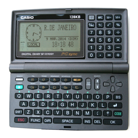
SF-5590SY
R
Table of
Contents
Previous
Page
Next
Page
1
2
3
4
5
Advertisement
Table of Contents
Need help?
Do you have a question about the SF-5590SY and is the answer not in the manual?
Ask a question
Questions and answers
Related Manuals for Casio SF-5590SY
Organizer Casio SF-5590SY User Manual
(40 pages)
Organizer CASIO SF-5590SY User Manual
Casio organizer (40 pages)
PDA CASIO INTERFACE UNIT CONVERSION LIST DIARY Manual
(9 pages)
Organizer Casio SF-5580E Service Manual
(33 pages)
Organizer Casio SF-5580 Owner's Manual
Casio sf-5580 diary-digital: owners manual (79 pages)
Organizer CASIO SF-5580 Owner's Manual
Casio organizer (42 pages)
Organizer CASIO SF-5780 Owner's Manual
Casio organizer (42 pages)
Organizer CASIO SF-5100 Owner's Manual
Digital diary (70 pages)
Organizer CASIO SF-5100 Owner's Manual
Digital diary (71 pages)
Organizer CASIO SF-5300 Owner's Manual
Digital diary (71 pages)
Organizer CASIO SF-5580RS Owner's Manual
Organizer casio (41 pages)
Organizer CASIO SF-5600AR Owner's Manual
Organizer casio (95 pages)
Organizer CASIO SF-5300E Owner's Manual
Organizer casio (53 pages)
Organizer CASIO SF-5300B Owner's Manual
Organizer (53 pages)
Organizer Casio SF-5790SY PLUS Service Manual & Parts List
(33 pages)
Organizer Casio SF-5990SY PLUS Service Manual & Parts List
(33 pages)
This manual is also suitable for:
Sf-5590sy plus
Sf-5790sy
Sf-5790sy plus
Sf-5990sy plus
Sf-5990sy
Table of Contents
Print
Rename the bookmark
Delete bookmark?
Delete from my manuals?
Login
Sign In
OR
Sign in with Facebook
Sign in with Google
Upload manual
Upload from disk
Upload from URL


Need help?
Do you have a question about the SF-5590SY and is the answer not in the manual?
Questions and answers