Advertisement
Quick Links
Download this manual
See also:
Instruction Manual
SAFETY-RELATED COMPONENT WARNING!!
COMPONENTS IDENTIFIED BY MARK
SCHEMATIC DIAGRAM AND IN THE PARTS LIST
ARE CRITICAL FOR RISK OF FIRE AND ELEC-
TRIC SHOCK. REPLACE THESE COMPONENTS
WITH ONKYO PARTS WHOSE PARTS NUMBERS
APPEAR AS SHOWN IN THIS MANUAL.
MAKE LEAKAGE-CURRENT OR RESISTANCE
MEASUREMENTS TO DETERMINE THAT EXPO-
SED PARTS ARE ACCEPTABLY INSULATED FORM
THE SUPPLY CIRCUIT BEFORE RETURNING THE
APPLIANCE TO THE CUSTOMER.
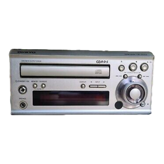
CD RECEIVER
MODEL CR-305X
Silver models
120 V AC,60 Hz
UDD,UDT
230 V AC,50 Hz
UPP
220 - 230 V AC,50/60Hz
UGT,UGR
TABLE OF CONTENTS
Specifications -----------------------------------------------------------
Caution on replacement of optical pickup --------------------------
Protection of eyes from laser bam during servicing ---------------
ON THE
Service procedures -----------------------------------------------------
Front panel view ------------------------------------------------------
Rear panel view -------------------------------------------------------
Remote controller ----------------------------------------------------
Microprocessor connection diagram --------------------------------
Microprocessor terminal descriptions ------------------------------
IC Block diagram and descriptions ---------------------------------
CD Mechanism exploded view --------------------------------------
Replacement of optical pickup ---------------------------------------
Chassis exploded view parts list -------------------------------------
Chassis exploded view -----------------------------------------------
Block diagram ---------------------------------------------------------
Wiring view ------------------------------------------------------------
Printed circuit board view parts list --------------------------------7
Schematic diagram (Amplifier section) -----------------------------
Printed circuit board view 1-------------------------------------------
Schematic diagram (CD & Microprocessor section) -------------
Printed circuit board view 2-------------------------------------------
Printed circuit board view 3-------------------------------------------
CD Adjustment procedures ------------------------------------------
Clock adjustment procedures ----------------------------------------
Assembling of pad ---------------------------------------------------
packing view ---------------------------------------------------------
CR-305X
Ref.NO.3654
082000
2
2
3
4
5
6
7
8
9
10
19
21
22
23
25
26
27
29
31
33
35
37
39
40
41
42
Advertisement

Summary of Contents for Onkyo CR-305X
- Page 1 ARE CRITICAL FOR RISK OF FIRE AND ELEC- Remote controller ---------------------------------------------------- TRIC SHOCK. REPLACE THESE COMPONENTS Microprocessor connection diagram -------------------------------- WITH ONKYO PARTS WHOSE PARTS NUMBERS Microprocessor terminal descriptions ------------------------------ APPEAR AS SHOWN IN THIS MANUAL. IC Block diagram and descriptions ---------------------------------...
-
Page 2: Specifications
CR-305X SPECIFICATIONS AMPLIFIER TUNER Po w er Output: 2 x 20 watts at 4 ohms 1 kHz DIN Tuning range 2 x 17 watts at 6 ohms 1 kHz DIN FM: 87.9 to 107.9 MHz (200 kHz steps) AM: 530 to 1710 kHz (10 kHz steps) (U.S. - Page 3 CR-305X PROTECTION OF EYES FROM LASER BEAM DURING SERVICING This set employs a laser. Therefore, be sure to follow carefully Laser Diode Properties the instructions below when servicing. Material: GaAS/GaALAs Wavelength: 780nm WARNING!! Laser output: max. 0.5mW* SERVICE WARNING : DO NOT APPROACH THE Emission Duration: continuous LASER EXIT WITH THE EYE TOO CLOSELY.
- Page 4 CR-305X SERVICE PROCEDURE 1. Replacing the fuses 5. Removement of tray 1.Remove the top cover This symbol located near the fuse indicates that the 2.Turn the locked screw to the clockwise to release the lock of gear. fuse used is show operating type, For continued protection against...
- Page 5 CR-305X...
- Page 6 CR-305X...
- Page 7 CR-305X IC BLOCK DIAGRAM AND DESCRIPTIONS Q101:CXA1992BR (RF Signal Processing Servo Amplifier) Block Diagram RF SUMMING AMP PD1 IV PD2 IV FE - BIAS SENS2 ↓ SENS1 LASER POWER CONTROL F IV AMP C.OUT FE AMP E IV AMP DFCT...
- Page 8 CR-305X Terminal description No. Symbol Description No. Symbol Description Focus error amplifier output. 26 SENS2 Outputs DFCT2, MIRR, BALL, TGL, FOL, and Connected internally to the window comparator input others according to the command from the CPU. for bias adjustment.
- Page 9 CR-305X Q301:CXD2589Q (CD Digital Signal Processor) Bloch Diagram 51 25 26 27 28 47 49 54 56 50 39 41 55 40 42 44 62 TES1 TEST Clock Error XRST Generator Corrector RMUT Interface demodurator LMUT Serial-In Interface ASYI Asymmetry...
- Page 10 CR-305X Terminal description No. Symbol Description No. Symbol Description D/A interface. Bit clock output. — D/A interface. Bit clock input. Left-channel zero detection flag. LMUT BCKI RMUT Right-channel zero detection flag. — Power supply (+5V). SQSO readout clock input. —...
- Page 11 CR-305X Q401:TC9273N-007 (Analog function switch) LEVEL SHIFT AND SHIFT REGISTER GND CK DATA STB Q402:TC9162AF Analog function switch VSS GND VDD COM1 COM1 COM2 COM2 COM3 COM3 DATA SHIFT REGISTER...
- Page 17 BLOCK DIAGRAM Q403,Q404 ACOUSTIC PRESENCE CONTROL POWER AMP. Q401 INPUT SELECTOR TC9273N-007 VOLUME TAPE R425 PLAY P551 Q603,Q405 SPEAKERS MUTING Q601,Q602 PLAY AMP. MUTE +12V Q402 13 ST CK 14 USA & Canadian models only PLAY ACOUSTIC PRESENCE Q704 15 CK DATA 15 CONTROL P405...
- Page 25 923A 922A...


Need help?
Do you have a question about the CR-305X and is the answer not in the manual?
Questions and answers