Table of Contents
Advertisement
Quick Links
Advertisement
Chapters
Table of Contents

Related Manuals for IEI Technology ICEROCK3-T10

Summary of Contents for IEI Technology ICEROCK3-T10
-
Page 1: User Manual
ICEROCK3-T10 Tablet PC MODEL: ICEROCK3-T10 Industrial Tablet PC Intel® Core™ i7 CPU, 8 GB DDR3 SDRAM, USB 3.0, Micro HDMI, microSD Slot, 802.11b/g/n Wireless, RFID, Barcode Scanner, Mobile 3.75G, IP 65, RoHS Compliant User Manual Page i Rev. 1.01 – May 20, 2015... - Page 2 ICEROCK3-T10 Tablet PC Revision Date Version Changes May 20, 2015 1.01 Added the following sections: – Section 3.10: Using 3-in-1 Combo Reader – Section 4.10: SCR Driver – Section 4.11: MSR Driver – Section 4.12: Fingerprint Reader Driver September 25, 2014 1.00...
- Page 3 ICEROCK3-T10 Tablet PC Copyright COPYRIGHT NOTICE In no event will the manufacturer be liable for direct, indirect, special, incidental, or consequential damages arising out of the use or inability to use the product or documentation, even if advised of the possibility of such damages.
-
Page 4: Table Of Contents
ICEROCK3-T10 Tablet PC Table of Contents 1 INTRODUCTION......................1 1.1 O ........................2 VERVIEW 1.2 M ....................3 ODEL ARIATIONS 1.3 F ........................3 EATURES 1.4 F ......................4 RONT ANEL 1.4.1 Status Indicators ....................4 1.5 R ....................... 6 ANEL 1.6 S... - Page 5 ICEROCK3-T10 Tablet PC 3.10 U -1 C )............35 SING OMBO EADER PTIONAL 4 DRIVER INSTALLATION..................38 4.1 A ................39 VAILABLE OFTWARE RIVERS 4.2 I ® C ..................39 NTEL HIPSET RIVER 4.3 I ® G ..................40 NTEL...
- Page 6 ICEROCK3-T10 Tablet PC 5.4 C ........................79 HIPSET 5.4.1 PCH-IO Configuration ..................80 5.4.2 System Agent (SA) Configuration ..............83 5.4.2.1 Graphics Configuration................84 5.4.2.2 Memory Configuration ................86 5.5 B ........................86 5.6 S ......................... 88 ECURITY 5.7 E .........................
- Page 7 ICEROCK3-T10 Tablet PC List of Figures Figure 1-1: ICEROCK3-T10 ......................2 Figure 1-2: Front Panel ........................4 Figure 1-3: Front Panel LED Indicators ..................4 Figure 1-4: Rear Panel........................6 Figure 1-5: Side Panel ........................6 Figure 1-6: Top Panel ........................7 Figure 1-7: Bottom Panel .......................7 Figure 1-8: Dimensions (units in mm) ..................10...
- Page 8 ICEROCK3-T10 Tablet PC Figure 3-23: u-center Window .....................31 Figure 3-24: VESA Mount Screw Holes ..................31 Figure 3-25: Left Side I/O Connectors ..................32 Figure 3-26: Audio Connectors ....................33 Figure 3-27: Micro HDMI Device Connection................34 Figure 3-28: USB Device Connection ..................35 Figure 3-29: 3-in-1 Combo Reader ....................35 Figure 3-30: Combo Reader Installation ..................36...
- Page 9 ICEROCK3-T10 Tablet PC Figure 4-27: Installing Driver Window ..................56 Figure 4-28: Driver Installation Complete Window ..............57 Figure 4-29: Device Manager Window ..................57 Figure 4-30: Fingerprint Reader Driver Folder ................58 Figure 4-31: Fingerprint Reader Driver InstallShield Wizard ...........59 Figure 6-1: Unlock Battery Latches ....................92 Figure 6-2: Battery Installation....................93...
- Page 10 ICEROCK3-T10 Tablet PC List of Tables Table 1-1: Model Variations ......................3 Table 1-2: Status Indicators......................5 Table 1-3: Technical Specifications....................9 Table 2-1: Packing List.........................13 Table 2-2: Optional Items......................14 Table 5-1: BIOS Navigation Keys ....................62 Page x...
- Page 11 ICEROCK3-T10 Tablet PC BIOS Menus BIOS Menu 1: Main ........................63 BIOS Menu 2: Advanced ......................65 BIOS Menu 3: ACPI Configuration ....................65 BIOS Menu 4: RTC Wake Settings ....................66 BIOS Menu 5: Trusted Computing ....................68 BIOS Menu 6: CPU Configuration ....................69 BIOS Menu 7: SATA Configuration .....................71...
-
Page 13: Introduction
ICEROCK3-T10 Tablet PC Chapter Introduction Page 1... -
Page 14: Overview
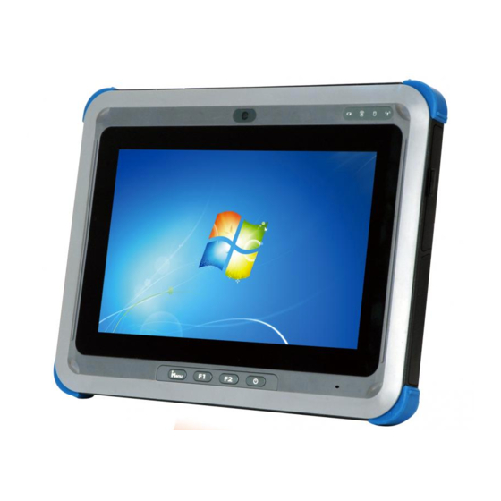
ICEROCK3-T10 Tablet PC 1.1 Overview Figure 1-1: ICEROCK3-T10 The ICEROCK3-T10 is an industrial tablet PC with a 10.1 inch touchscreen and an IP 65 rating protection. The ICEROCK3-T10 features an Intel® Celeron® 1007U or Intel® Core™ i7-3517 processor with DDR3 SDRAM on-board. -
Page 15: Model Variations
ICEROCK3-T10 Tablet PC 1.2 Model Variations The ICEROCK3-T10 series has three models. All of the models are equipped with a projected capacitive touchscreen, IPS, 802.11b/g/n Wi-Fi and Bluetooth v3.0. The model variations are listed below. Models Intel Memory 3.75G RFID... -
Page 16: Front Panel
Figure 1-2: Front Panel 1.4.1 Status Indicators Figure 1-3: Front Panel LED Indicators There are four LED indicators on the front panel of the ICEROCK3-T10 as show in the figure above. The following table contains descriptions of their functions. Page 4... -
Page 17: Table 1-2: Status Indicators
ICEROCK3-T10 Tablet PC Status Indicator Description Off: the system is fully charged or not being charged Battery Battery 1 is being charged. Solid red: Battery 2 is being charged. Solid blue: Battery 1 is low Blinking red: Battery 2 is low... -
Page 18: Rear Panel
ICEROCK3-T10 Tablet PC 1.5 Rear Panel The rear panel consists of the built-in battery and VESA mounting holes. The optional 5-megapixel camera is also located on the rear panel. Figure 1-4: Rear Panel 1.6 Side Panels The right side panel has a barcode on/off button. The left side panel consists of I/O ports and slots. -
Page 19: Top Panel
ICEROCK3-T10 Tablet PC 1.7 Top Panel The barcode scanner is located on the top panel shown in the following diagram. Figure 1-6: Top Panel 1.8 Bottom Panel The bottom panel has a USB 3.0 connector for installing USB peripheral devices or the charging adapter. -
Page 20: Technical Specifications
ICEROCK3-T10 Tablet PC 1.9 Technical Specifications The technical specifications for the ICEROCK3-T10 systems are listed in the table below. System ICEROCK3-T10 1.700 GHz Intel® Core ™ i7-3517U processor 1.50 GHz Intel® Celeron® processor 1007U Chipset Intel® HM76 Memory 4.0 GB DDR3 SDRAM on board Optional 4.0 GB DDR3 SDRAM SO-DIMM... -
Page 21: Table 1-3: Technical Specifications
ICEROCK3-T10 Tablet PC System ICEROCK3-T10 Power Battery Battery 1 (standard): 3700 mAH Li-ion battery pack with battery capacity LED indicators (five working hours) Battery 2 (optional): internal 3700 mAH battery pack (five working hours) Power Input 19 V DC input... -
Page 22: Dimensions
ICEROCK3-T10 Tablet PC 1.10 Dimensions Figure 1-8: Dimensions (units in mm) Page 10... -
Page 23: Unpacking
ICEROCK3-T10 Tablet PC Chapter Unpacking Page 11... -
Page 24: Unpacking
Install SIM card or microSD card (if necessary) Step 4: Mount the tablet PC Step 5: Connect peripheral devices to the side panel of the ICEROCK3-T10 Step 6: S t e p 0 : 2.1 Unpacking To unpack the ICEROCK3-T10, follow the steps below:... -
Page 25: Packing List
ICEROCK3-T10 Tablet PC Remove the ICEROCK3-T10 and the packing material out of the box. Step 2: Make sure all the components listed in the packing list are present. Step 3: S t e p 0 : 2.2 Packing List The ICEROCK3-T10 tablet PC is shipped with the following components:... -
Page 26: Table 2-2: Optional Items
ICEROCK3-T10 Tablet PC These optional items are also available. Item Image 3-in-1 combo reader (P/N: ICEROCK3-3IN1-R10) Charging station (P/N: ICEROCK3-CR01-R10) Carrying case (P/N: 7Z000-ICEROCK3-10POUCH) Table 2-2: Optional Items Page 14... -
Page 27: Installation
ICEROCK3-T10 Tablet PC Chapter Installation Page 15... -
Page 28: Charge The System
To charge the ICEROCK3-T10, follow the steps below. Install the charging adapter to the ICEROCK3-T10. Secure the charging adapter Step 1: by tightening the two retention screws on either side of the adapter. -
Page 29: Figure 3-2: Charge Status Led
ICEROCK3-T10 Tablet PC Figure 3-2: Charge Status LED The battery 1 capacity can be viewed by pressing the button on the battery pack Step 4: (Figure 3-3). Figure 3-3: Battery Capacity Indicators The user can also turn on the system to check the battery capacity via the... -
Page 30: Optional Charging Station
The ICEROCK3-T10 can be charged through the optional charging station. To charge the system, install the ICEROCK3-T10 into the charging station as shown in Figure 3-5. Then, connect the charging station with a power source through the power adapter came with the ICEROCK3-T10 package. -
Page 31: Power-Up The System
ICEROCK3-T10 Tablet PC Figure 3-5: Charge the System through Charging Station 3.2 Power-up the System To power-up the system, push the power button on the top panel for few seconds until the power button lights up. Figure 3-6: Power Button Location... -
Page 32: Sd Card Installation
ICEROCK3-T10 Tablet PC 3.3 SD Card Installation This section covers the installation of a microSD card. Open the I/O cover on the side panel. Locate the microSD card slot. Step 1: Install the microSD card in the slot indicated below. -
Page 33: Sim Card Installation (Optional)
3.4 SIM Card Installation (Optional) This section covers the installation of a SIM card for mobile network connections on the ICEROCK3-T10 models with optional mobile 3.75G module. Open the I/O cover on the side panel. Locate the SIM card slot. -
Page 34: Figure 3-9: Pcsctool Location
ICEROCK3-T10 Tablet PC Figure 3-9: PcscTool Location The NXP PCSC Tool window appears ( Step 4: F igure 3-10). Figure 3-10: NXP PCSC Tool Screen Select Automatic from the Mode menu ( Step 5: F igure 3-11). Page 22... -
Page 35: Figure 3-11: Nxp Pcsc Tool - Mode Selection
ICEROCK3-T10 Tablet PC Figure 3-11: NXP PCSC Tool – Mode Selection Choose Select a Reader from the Reader menu ( Step 6: F igure 3-12). Figure 3-12: NXP PCSC Tool – Reader Selection The Select the reader window prompts. Select a RFID reader and click OK. See Step 7: Figure 3-13. -
Page 36: Figure 3-14: Nxp Pcsc Tool - Read Rfid Card
ICEROCK3-T10 Tablet PC Click the Arrow button shown in Figure 3-14 to read RFID card. Step 8: Figure 3-14: NXP PCSC Tool – Read RFID Card Use the RFID reader to read a RFID card. The RFID reader is located on the Step 9: front panel as shown in Figure 3-15. -
Page 37: Using Barcode Scanner
ICEROCK3-T10 Tablet PC 3.6 Using Barcode Scanner Some models of the ICEROCK3-T10 have a barcode scanner on the top panel. To use the barcode scanner, follow the steps below. Check the barcode status indicator on the front panel to make sure the barcode Step 1: function is enabled (see Section 1.4.1). -
Page 38: Figure 3-17: Ezconfig-Scanning Installshield Wizard
ICEROCK3-T10 Tablet PC Figure 3-17: EZConfig-Scanning InstallShield Wizard Double click the EZConfig-Scanning icon on the desktop. The Step 4: EZConfig-Scanning window appears ( F igure 3-18). Figure 3-18: EZConfig-Scanning Window Page 26... -
Page 39: Figure 3-19: Ezconfig-Scanning - Port Settings
ICEROCK3-T10 Tablet PC Click the Port Settings button on the tool bar. Refer the following information to Step 5: configure the COM port settings for the barcode scanner. After the configuration, click the Config Comm button ( F igure 3-19). -
Page 40: Figure 3-20: Barcode On/Off Button And Barcode Status Indicator
ICEROCK3-T10 Tablet PC Push the barcode on/off button on the right side panel to turn on the barcode Step 7: scanner. The barcode status indicator on the front panel lights up in red (if the RFID reader is enabled at the same time, the indicator will turns from blue to purple). -
Page 41: Using Gps Evaluation Software
Figure 3-21: Barcode Information Display Area 3.7 Using GPS Evaluation Software To evaluate the GPS function on the ICEROCK3-T10 models with GPS module, please follow the instruction below. The GPS function is enabled by default in the BIOS menu. If the GPS function is Step 1: disabled, please go to Chipset ... -
Page 42: Figure 3-22: Gps Evaluation Software Location
ICEROCK3-T10 Tablet PC Figure 3-22: GPS Evaluation Software Location The InstallShield Wizard screen appears. Follow the step-by-step instruction of Step 3: the installation wizard to install the u-center GPS evaluation software. After the installation is complete, double click the u-center icon on the desktop. -
Page 43: Mounting The System
75 mm interface pad. The VESA mounting screw holes are located on the rear panel as shown in the following diagram. To mount the ICEROCK3-T10, please refer to the user manual that came with the mounting device. Figure 3-24: VESA Mount Screw Holes... -
Page 44: I/O Connectors
ICEROCK3-T10 Tablet PC 3.9 I/O Connectors The I/O connectors on the left side of the ICEROCK3-T10 extend the capabilities of the tablet PC but are not essential for operation (Figure 3-25). Figure 3-25: Left Side I/O Connectors 3.9.1 Audio connectors (Mic-in and Headphones) The audio jacks on the external audio connector enable the ICEROCK3-T10 to be connected to a stereo sound setup. -
Page 45: Micro Hdmi Device Connection
Step 0: 3.9.2 Micro HDMI Device Connection There is one Micro HDMI connector on the left side of the ICEROCK3-T10. To connect a HDMI device, please follow the instructions below. Located the Micro HDMI connector. The location of the Micro HDMI connector Step 1: is shown in Figure 3-25. -
Page 46: Usb Device Connection
Figure 3-27: Micro HDMI Device Connection Insert the device connector. Once aligned, gently insert the HDMI device Step 3: connector into the connector on the ICEROCK3-T10. Step 0: 3.9.3 USB Device Connection There are two USB 3.0 connectors on the side panel. To connect a USB device, please follow the instructions below. -
Page 47: Using 3-In-1 Combo Reader (Optional)
ICEROCK3-T10. Step 0: 3.10 Using 3-in-1 Combo Reader (Optional) The 3-in-1 combo reader is an optional item for the ICEROCK3-T10. The combo reader combines fingerprint reader, smart card reader (SCR) and magnetic stripe reader (MSR) into one compact device. -
Page 48: Figure 3-30: Combo Reader Installation
ICEROCK3-T10 Tablet PC To install the combo reader to the ICEROCK3-T10, please follow the steps below. Align the USB connectors on the reader with the two USB 3.0 connectors on the Step 1: left side panel of the ICEROCK3-T10. Insert and connect the USB connectors to install the combo reader. - Page 49 ICEROCK3-T10 Tablet PC Install the drivers for these three reader by following the instructions described in Step 4: Chapter 4: Section 4.10: SCR Driver Section 4.11: MSR Driver Section 4.12: Fingerprint Reader Driver Page 37...
-
Page 50: Driver Installation
ICEROCK3-T10 Tablet PC Chapter Driver Installation Page 38... -
Page 51: Available Software Drivers
USB 3.0 driver Wireless LAN driver Connect the Utility CD came with the ICEROCK3-T10 to the system and follow the installation instructions given below to install the drivers. NOTE: The chipset driver must be installed first, then the graphics driver. After finishing installing the chipset driver and graphics driver, the user can continue to install other drivers in any order. -
Page 52: Intel® Graphics Driver
ICEROCK3-T10 Tablet PC Figure 4-1: Chipset Driver Location There are three folders, and each folder contains chipset related drivers to be Step 2: installed. Double click the setup file in each folder and follow the step-by-step instruction of the installation wizard to install the drivers. -
Page 53: Figure 4-2: Graphics Driver Location
ICEROCK3-T10 Tablet PC Figure 4-2: Graphics Driver Location Double click the setup file in the folder. The Intel® Graphics Driver Step 2: InstallShield Wizard appears ( F igure 4-3). 4 7 4 Figure 4-3: Intel® Graphics Driver InstallShield Wizard Follow the step-by-step instruction of the installation wizard to install the Step 3: graphics driver. -
Page 54: G Driver
ICEROCK3-T10 Tablet PC 4.4 3.75G Driver To install the driver for the 3.75G module, please follow the steps below. Select GOBI 3000 from the list of the driver CD. Locate the driver setup file in Step 1: the Drivers folder as shown in F igure 4-6. -
Page 55: Audio Driver
ICEROCK3-T10 Tablet PC Figure 4-5: 3.75G Driver InstallShield Wizard Follow the step-by-step instruction of the installation wizard to install the HD Step 3: Audio driver. 4.5 Audio Driver To install the driver for the speaker and the microphone, please follow the steps below. -
Page 56: Figure 4-6: Speaker And Microphone Driver Location
ICEROCK3-T10 Tablet PC Figure 4-6: Speaker and Microphone Driver Location Double click the setup file in the folder. The InstallShield Wizard screen Step 2: appears ( F igure 4-7). Figure 4-7: Realtek HD Audio Driver InstallShield Wizard Follow the step-by-step instruction of the installation wizard to install the HD Step 3: Audio driver. -
Page 57: Bluetooth Driver
ICEROCK3-T10 Tablet PC 4.6 Bluetooth Driver To install the Bluetooth driver, please follow the steps below. Select Wireless LAN & Bluetooth from the list of the driver CD. Select the Step 1: Bluetooth folder as shown in F igure 4-8. -
Page 58: Rfid Driver
ICEROCK3-T10 Tablet PC Figure 4-9: Bluetooth Driver InstallShield Wizard Follow the step-by-step instruction of the installation wizard to install the Step 3: Bluetooth driver. 4.7 RFID Driver To install the RFID driver, please follow the steps below. Select RFID from the list of the driver CD. Double click the setup file in the WIN7... -
Page 59: Figure 4-10: Rfid Driver Folder
ICEROCK3-T10 Tablet PC Figure 4-10: RFID Driver Folder Follow the step-by-step instruction of the installation wizard (Figure 4-11) to Step 2: install the RFID driver. Figure 4-11: RFID Driver Installation Page 47... -
Page 60: Usb 3.0 Driver
NOTE: Two USB 3.0 drivers must be installed in order to enable all three USB 3.0 ports on the ICEROCK3-T10. One is included in the Chipset driver folder (see Section 4.2), and the other is in the USB 3.0 driver folder. -
Page 61: Wireless Lan Driver
ICEROCK3-T10 Tablet PC Figure 4-13: USB 3.0 Driver InstallShield Wizard Follow the step-by-step instruction of the installation wizard to install the Step 3: graphics driver. 4.9 Wireless LAN Driver To install the wireless LAN driver, please follow the steps below. -
Page 62: Figure 4-14: Wireless Lan Driver Location
ICEROCK3-T10 Tablet PC Figure 4-14: Wireless LAN Driver Location Double click the setup file in the Install_CD folder. The InstallShield Wizard Step 2: screen appears (Figure 4-15). Figure 4-15: Wireless LAN InstallShield Wizard Follow the step-by-step instruction of the installation wizard to install the Step 3: Wireless LAN driver. -
Page 63: Scr Driver (Optional)
ICEROCK3-T10 Tablet PC 4.10 SCR Driver (Optional) Follow the steps below to install the SCR driver. Open the SCR driver folder and locate the usbser.sys file at Step 1: SCR\DRIVER\Windows Driver (Singular). See Figure 4-16. Copy the usbser.sys file to C:\WINDOWS\system32\drivers directory. -
Page 64: Figure 4-18: Update Driver Software Window
ICEROCK3-T10 Tablet PC The Update Driver Software window appears. Select Browse my computer Step 3: for driver software. Figure 4-18: Update Driver Software Window The following window appears. Press/Click the Browse button to specify the Step 4: SCR driver directory (SCR\DRIVER\Windows Driver (Singular)). Then, press/click the Next button. -
Page 65: Figure 4-20: Installing Driver Window
ICEROCK3-T10 Tablet PC The following window (Figure 4-20) appears as the driver is installed. Step 5: Figure 4-20: Installing Driver Window After the driver installation process is complete, a confirmation screen appears. Step 6: Click Close to exit the program. -
Page 66: Msr Driver (Optional)
ICEROCK3-T10 Tablet PC The Device Manager Window now shows the installed SCR driver. Step 7: Figure 4-22: Device Manager Window 4.11 MSR Driver (Optional) Follow the steps below to install the MSR driver. Open the MSR driver folder and locate the usbser.sys file at MSR\Windows Step 1: Driver (Singular). -
Page 67: Figure 4-24: Device Manager - Update Driver Software
ICEROCK3-T10 Tablet PC Open the Device Manager window. Long press or right click Singular VCOM Step 2: Card Reader. Select Update Driver Software from the pop-up window. Figure 4-24: Device Manager - Update Driver Software The Update Driver Software window appears. Select Browse my computer Step 3: for driver software. -
Page 68: Figure 4-26: Browse For Driver Software Window
ICEROCK3-T10 Tablet PC The following window appears. Press/Click the Browse button to specify the Step 4: MSR driver directory (MSR\Windows Driver (Singular)). Then, press/click the Next button. Figure 4-26: Browse for Driver Software Window The following window (Figure 4-27) appears as the driver is installed. -
Page 69: Figure 4-28: Driver Installation Complete Window
ICEROCK3-T10 Tablet PC After the driver installation process is complete, a confirmation screen appears. Step 6: Click Close to exit the program. Figure 4-28: Driver Installation Complete Window The Device Manager Window now shows the installed MSR driver. Step 7:... -
Page 70: Fingerprint Reader Driver (Optional)
ICEROCK3-T10 Tablet PC 4.12 Fingerprint Reader Driver (Optional) Follow the steps below to install the fingerprint reader driver. The fingerprint reader driver is located in the folder shown in Figure 4-30. Step 1: Double click the setup.exe file in this folder to install the driver. -
Page 71: Figure 4-31: Fingerprint Reader Driver Installshield Wizard
ICEROCK3-T10 Tablet PC Figure 4-31: Fingerprint Reader Driver InstallShield Wizard Follow the step-by-step instruction of the installation wizard to install the Step 3: fingerprint reader driver. Page 59... -
Page 72: Bios Setup
ICEROCK3-T10 Tablet PC Chapter BIOS Setup Page 60... -
Page 73: Introduction
ICEROCK3-T10 Tablet PC 5.1 Introduction The BIOS is programmed onto the BIOS chip. The BIOS setup program allows changes to certain system settings. This chapter outlines the options that can be changed. NOTE: Some of the BIOS options may vary throughout the life cycle of the product and are subject to change without prior notice. -
Page 74: Getting Help
ICEROCK3-T10 Tablet PC Function Decrease the numeric value or make changes Page up Move to the next page Page down Move to the previous page Main Menu – Quit and do not save changes into CMOS Status Page Setup Menu and Option Page Setup Menu --... -
Page 75: Main
ICEROCK3-T10 Tablet PC 5.2 Main The Main BIOS menu ( B IOS Menu 1) appears when the BIOS Setup program is entered. 5 8 4 The Main menu gives an overview of the basic system information. Aptio Setup Utility – Copyright (C) 2012 American Megatrends, Inc. -
Page 76: Advanced
ICEROCK3-T10 Tablet PC The Main menu has two user configurable fields: System Date [xx/xx/xx] Use the System Date option to set the system date. Manually enter the day, month and year. System Time [xx:xx:xx] Use the System Time option to set the system time. Manually enter the hours, minutes and seconds. -
Page 77: Acpi Settings
ICEROCK3-T10 Tablet PC Aptio Setup Utility – Copyright (C) 2012 American Megatrends, Inc. Main Advanced Chipset Boot Security Save & Exit > ACPI Settings System ACPI Parameters > RTC Wake Settings > Trusted Computing > CPU Configuration > SATA Configuration ---------------------- >... -
Page 78: Rtc Wake Settings
ICEROCK3-T10 Tablet PC ACPI Sleep State [S3 only (Suspend to RAM)] Use the ACPI Sleep State option to specify the sleep state the system enters when it is not being used. The system enters S1 (POS) sleep state. The S1 only (CPU Stop system appears off. - Page 79 ICEROCK3-T10 Tablet PC Wake System with Fixed Time [Disabled] Use the Wake System with Fixed Time option to specify the time the system should be roused from a suspended state. The real time clock (RTC) cannot generate a wake...
-
Page 80: Trusted Computing
ICEROCK3-T10 Tablet PC 5.3.3 Trusted Computing Use the Trusted Computing menu (BIOS Menu 5) to configure settings related to the Trusted Computing Group (TCG) Trusted Platform Module (TPM). Aptio Setup Utility – Copyright (C) 2012 American Megatrends, Inc. Advanced Configuration... -
Page 81: Cpu Configuration
ICEROCK3-T10 Tablet PC 5.3.4 CPU Configuration Use the CPU Configuration menu ( B IOS Menu 6) to view detailed CPU specifications 5 8 4 and configure the CPU. Aptio Setup Utility – Copyright (C) 2012 American Megatrends, Inc. Advanced CPU Configuration... -
Page 82: Hyper Threading [Enabled]
ICEROCK3-T10 Tablet PC Intel SMX Technology: Indicates if Intel SMX Technology is supported by the CPU. 64-bit: Indicates if 64-bit system is supported by the CPU. L1 Data Cache: Lists the amount of data storage space on the L1 cache. -
Page 83: Sata Configuration
ICEROCK3-T10 Tablet PC 5.3.5 SATA Configuration Use the SATA Configuration menu ( B IOS Menu 7) to change and/or set the 5 8 4 configuration of the SATA devices installed in the system. Aptio Setup Utility – Copyright (C) 2012 American Megatrends, Inc. -
Page 84: Intel(R) Rapid Start Technology
ICEROCK3-T10 Tablet PC 5.3.6 Intel(R) Rapid Start Technology The Intel® Rapid Start Technology is disabled by default. Aptio Setup Utility – Copyright (C) 2012 American Megatrends, Inc. Advanced Intel(R) Rapid Start Technology [Disabled] --------------------- : Select Screen : Select Item... -
Page 85: Usb Configuration
ICEROCK3-T10 Tablet PC 5.3.7 USB Configuration Use the USB Configuration menu ( B IOS Menu 9) to read USB configuration information 5 8 4 and configure the USB settings. Aptio Setup Utility – Copyright (C) 2012 American Megatrends, Inc. Advanced... -
Page 86: Iwdd Serial Ports Configuration
ICEROCK3-T10 Tablet PC Legacy USB support disabled Disabled Legacy USB support disabled if no USB devices are Auto connected 5.3.8 iWDD Serial Ports Configuration Use the iWDD Serial Ports Configuration menu ( B IOS Menu 10) to set or change the configurations for the serial ports. -
Page 87: Serial Port N Configuration
ICEROCK3-T10 Tablet PC 5.3.8.1 Serial Port n Configuration Use the Serial Port n Configuration menu ( B IOS Menu 11) to configure the serial port n. Aptio Setup Utility – Copyright (C) 2012 American Megatrends, Inc. Advanced Serial Port 1 Configuration... -
Page 88: Serial Port [Enabled]
ICEROCK3-T10 Tablet PC Serial Port I/O port address is 3F8h and the interrupt IO=3F8h; address is IRQ4 IRQ=4 Serial Port I/O port address is 3E8h and the interrupt IO=3E8h; address is IRQ3, 4 IRQ=3, 4 Serial Port I/O port address is 2F8h and the interrupt IO=2F8h;... -
Page 89: H/W Monitor
ICEROCK3-T10 Tablet PC Serial Port I/O port address is 3E8h and the interrupt IO=3E8h; address is IRQ3, 4 IRQ=3, 4 Serial Port I/O port address is 2E8h and the interrupt IO=2E8h; address is IRQ3, 4 IRQ=3, 4 5.3.9 H/W Monitor The H/W Monitor menu ( B IOS Menu 12) shows the operating temperature. -
Page 90: Iei Feature
ICEROCK3-T10 Tablet PC 5.3.10 IEI Feature Use the IEI Feature menu ( B IOS Menu 13) to configure One Key Recovery function. Aptio Setup Utility – Copyright (C) 2012 American Megatrends, Inc. Advanced iEi Feature Auto Recovery Function Reboot and recover... -
Page 91: Chipset
ICEROCK3-T10 Tablet PC 5.4 Chipset Use the Chipset menu ( B IOS Menu 14) to access the PCH and System Agent (SA) 5 8 4 configuration menus. WARNING! Setting the wrong values for the Chipset BIOS selections in the Chipset BIOS menu may cause the system to malfunction. -
Page 92: Pch-Io Configuration
ICEROCK3-T10 Tablet PC 5.4.1 PCH-IO Configuration Use the PCH-IO Configuration menu ( B IOS Menu 15) to configure the PCH IO settings. Aptio Setup Utility – Copyright (C) 2012 American Megatrends, Inc. Chipset PCH-IO Configuration Control Detection of Azalia [Enabled] the Azalia device. -
Page 93: Barcode Function [Disabled]
ICEROCK3-T10 Tablet PC Camera Function (Back, CAMERA1) [Enabled] Use the Camera Function (Back, CAMERA1) option to enable or disable the camera function on the rear panel. Rear camera function disabled Disabled Rear camera function enabled Enabled EFAULT ... -
Page 94: Radio Function [Enabled]
ICEROCK3-T10 Tablet PC 3G Radio Function [Enabled] Use the 3G Radio Function option to enable or disable the 3G function. 3G function disabled Disabled 3G function enabled Enabled EFAULT WIFI Radio Function [Enabled] Use the WIFI Radio Function option to enable or disable the Wi-Fi function. -
Page 95: System Agent (Sa) Configuration
ICEROCK3-T10 Tablet PC 5.4.2 System Agent (SA) Configuration Use the System Agent (SA) Configuration menu (BIOS Menu 16) to configure the System Agent (SA) parameters. Aptio Setup Utility – Copyright (C) 2012 American Megatrends, Inc. Chipset VT-d [Disabled] Check to enable VT-d >... -
Page 96: Graphics Configuration
ICEROCK3-T10 Tablet PC 5.4.2.1 Graphics Configuration Use the Graphics Configuration menu ( B IOS Menu 17) to configure the graphics settings Aptio Setup Utility – Copyright (C) 2012 American Megatrends, Inc. Chipset Graphics Configuration Select which of IGFX/PEG/PCI Graphics Primary Display... - Page 97 ICEROCK3-T10 Tablet PC 128M 256M EFAULT 512M DVMT Total Gfx Mem [MAX] Use the DVMT Total Gfx Mem option to specify the maximum amount of memory that can be allocated for the internal graphics device. Configuration options are listed below.
-
Page 98: Memory Configuration
ICEROCK3-T10 Tablet PC 5.4.2.2 Memory Configuration Use the Memory Configuration menu (BIOS Menu 18) to display the memory information. Aptio Setup Utility – Copyright (C) 2012 American Megatrends, Inc. Chipset Memory Information Memory Frequency 1333 Mhz Total Memory 8192 MB (DDR3) --------------------- : Select Screen... - Page 99 ICEROCK3-T10 Tablet PC Bootup NumLock State [On] Use the Bootup NumLock State BIOS option to specify if the number lock setting must be modified during boot up. Allows the Number Lock on the keyboard to be EFAULT enabled automatically when the computer system boots up.
-
Page 100: Security
ICEROCK3-T10 Tablet PC UEFI Boot [Disabled] Use the UEFI Boot option to enable or disable to boot from the UEFI devices. Boot from UEFI devices is enabled. Enabled Boot from UEFI devices is disabled. Disabled EFAULT ... -
Page 101: Exit
ICEROCK3-T10 Tablet PC Administrator Password Use the Administrator Password to set or change a administrator password. User Password Use the User Password to set or change a user password. 5.7 Exit Use the Exit menu ( B IOS Menu 21) to load default BIOS values, optimal failsafe values 5 8 4 and to save configuration changes. -
Page 102: Restore User Defaults
ICEROCK3-T10 Tablet PC Restore Defaults Use the Restore Defaults option to load the optimal default values for each of the parameters on the Setup menus. F3 key can be used for this operation. Save as User Defaults Use the Save as User Defaults option to save the changes done so far as user defaults. -
Page 103: System Maintenance
ICEROCK3-T10 Tablet PC Chapter System Maintenance Page 91... -
Page 104: System Maintenance Introduction
ICEROCK3-T10 Tablet PC 6.1 System Maintenance Introduction If the components of the ICEROCK3-T10 fail they must be replaced, such as the wireless LAN module or the motherboard. Please contact the system reseller or vendor to purchase the replacement parts. 6.2 Motherboard Replacement In the case of motherboard failure, please contact an IEI sales representative, reseller or system vendor. -
Page 105: Figure 6-2: Battery Installation
ICEROCK3-T10 Tablet PC Figure 6-2: Battery Installation Lock the battery by rotating the battery latches to a proper position. Step 4: Page 93... -
Page 106: A Regulatory Compliance
ICEROCK3-T10 Tablet PC Appendix Regulatory Compliance Page 94... - Page 107 ICEROCK3-T10 Tablet PC DECLARATION OF CONFORMITY This equipment is in conformity with the following EU directives: EMC Directive 2004/108/EC Low-Voltage Directive 2006/95/EC RoHS II Directive 2011/65/EU Ecodesign Directive 2009/125/EC If the user modifies and/or install other devices in the equipment, the CE conformity declaration may no longer apply.
- Page 108 ICEROCK3-T10 Tablet PC Español [Spanish] IEI Integration Corp declara que el equipo cumple con los requisitos esenciales y cualesquiera otras disposiciones aplicables o exigibles de la Directiva 1999/5/CE. Ελληνική [Greek] IEI Integration Corp ΔΗΛΩΝΕΙ ΟΤΙ ΕΞΟΠΛΙΣΜΟΣ ΣΥΜΜΟΡΦΩΝΕΤΑΙ ΠΡΟΣ ΤΙΣ ΟΥΣΙΩΔΕΙΣ ΑΠΑΙΤΗΣΕΙΣ ΚΑΙ ΤΙΣ ΛΟΙΠΕΣ ΣΧΕΤΙΚΕΣ ΔΙΑΤΑΞΕΙΣ ΤΗΣ ΟΔΗΓΙΑΣ...
- Page 109 ICEROCK3-T10 Tablet PC Româna [Romanian] IEI Integration Corp declară că acest echipament este in conformitate cu cerinţele esenţiale şi cu celelalte prevederi relevante ale Directivei 1999/5/CE. Slovensko [Slovenian] IEI Integration Corp izjavlja, da je ta opreme v skladu z bistvenimi zahtevami in ostalimi relevantnimi določili direktive 1999/5/ES.
- Page 110 ICEROCK3-T10 Tablet PC FCC WARNING This equipment complies with Part 15 of the FCC Rules. Operation is subject to the following two conditions: This device may not cause harmful interference, and This device must accept any interference received, including interference that ...
-
Page 111: B Safety Precautions
ICEROCK3-T10 Tablet PC Appendix Safety Precautions Page 99... -
Page 112: Safety Precautions
Do not apply voltage levels that exceed the specified voltage range. Doing so may cause fire and/or an electrical shock. Electric shocks can occur if the ICEROCK3-T10 chassis is opened when the ICEROCK3-T10 is running. Do not drop or insert any objects into the ventilation openings of the ICEROCK3-T10. -
Page 113: Anti-Static Precautions
Electrostatic discharge (ESD) can cause serious damage to electronic components, including the ICEROCK3-T10. Dry climates are especially susceptible to ESD. It is therefore critical that whenever the ICEROCK3-T10 is opened and any of the electrical components are handled, the following anti-static precautions are strictly adhered to. -
Page 114: Product Disposal
Please follow the national guidelines for electrical and electronic product disposal. B.2 Maintenance and Cleaning Precautions When maintaining or cleaning the ICEROCK3-T10, please follow the guidelines below. B.2.1 Maintenance and Cleaning Prior to cleaning any part or component of the ICEROCK3-T10, please read the details below. Page 102... -
Page 115: Cleaning Tools
ICEROCK3-T10 Tablet PC Except for the LCD panel, never spray or squirt liquids directly onto any other components. To clean the LCD panel, gently wipe it with a piece of soft dry cloth or a slightly moistened cloth. The interior does not require cleaning. Keep fluids away from the interior. -
Page 116: Cbios Options
ICEROCK3-T10 Tablet PC Appendix BIOS Options Page 104... - Page 117 ICEROCK3-T10 Tablet PC Below is a list of BIOS configuration options in the BIOS chapter. System Date [xx/xx/xx] ......................64 System Time [xx:xx:xx] .......................64 ACPI Sleep State [S3 only (Suspend to RAM)] ..............66 Wake System with Fixed Time [Disabled] .................67 ...
- Page 118 ICEROCK3-T10 Tablet PC Primary IGFX Boot Display [VBIOS Default] ..............85 Bootup NumLock State [On]....................87 Quiet Boot [Enabled] ......................87 Option ROM Messages [Force BIOS].................87 UEFI Boot [Disabled] ......................88 Boot Option #1 [SATA PM: MRMAJ5A03…]..............88 ...
-
Page 119: D Terminology
ICEROCK3-T10 Tablet PC Appendix Terminology Page 107... - Page 120 ICEROCK3-T10 Tablet PC Audio Codec 97 (AC’97) refers to a codec standard developed by Intel® AC ’97 in 1997. Advanced Configuration and Power Interface (ACPI) is an OS-directed ACPI configuration, power management, and thermal management interface. Advanced Host Controller Interface (AHCI) is a SATA Host controller AHCI register-level interface.
- Page 121 ICEROCK3-T10 Tablet PC Direct Memory Access (DMA) enables some peripheral devices to bypass the system processor and communicate directly with the system memory. Dual Inline Memory Modules are a type of RAM that offer a 64-bit data DIMM bus and have separate electrical contacts on each side of the module.
- Page 122 ICEROCK3-T10 Tablet PC Liquid crystal display (LCD) is a flat, low-power display device that consists of two polarizing plates with a liquid crystal panel in between. Low-voltage differential signaling (LVDS) is a dual-wire, high-speed LVDS differential electrical signaling system commonly used to connect LCD displays to a computer.
-
Page 123: E Watchdog Timer
ICEROCK3-T10 Tablet PC Appendix Watchdog Timer Page 111... - Page 124 ICEROCK3-T10 Tablet PC NOTE: The following discussion applies to DOS environment. IEI support is contacted or the IEI website visited for specific drivers for more sophisticated operating systems, e.g., Windows and Linux. The Watchdog Timer is provided to ensure that standalone systems can always recover from catastrophic conditions that cause the CPU to crash.
- Page 125 ICEROCK3-T10 Tablet PC NOTE: When exiting a program it is necessary to disable the Watchdog Timer, otherwise the system resets. Example program: ; INITIAL TIMER PERIOD COUNTER W_LOOP: AX, 6F02H ;setting the time-out value BL, 30 ;time-out value is 48 seconds ;...
-
Page 126: F Hazardous Materials Disclosure
ICEROCK3-T10 Tablet PC Appendix Hazardous Materials Disclosure Page 114... -
Page 127: Hazardous Materials Disclosure Table For Ipb Products Certified As Rohs Compliant Under 2002/95/Ec Without Mercury
ICEROCK3-T10 Tablet PC F.1 Hazardous Materials Disclosure Table for IPB Products Certified as RoHS Compliant Under 2002/95/EC Without Mercury The details provided in this appendix are to ensure that the product is compliant with the Peoples Republic of China (China) RoHS standards. The table below acknowledges the presences of small quantities of certain materials in the product, and is applicable to China RoHS only. - Page 128 ICEROCK3-T10 Tablet PC Part Name Toxic or Hazardous Substances and Elements Lead Mercury Cadmium Hexavalent Polybrominated Polybrominated (Pb) (Hg) (Cd) Chromium Biphenyls Diphenyl Ethers (CR(VI)) (PBB) (PBDE) Housing Display Printed Circuit Board Metal Fasteners Cable Assembly Fan Assembly Power Supply...
- Page 129 ICEROCK3-T10 Tablet PC 此附件旨在确保本产品符合中国 RoHS 标准。以下表格标示此产品中某有毒物质的含量符 合中国 RoHS 标准规定的限量要求。 本产品上会附有”环境友好使用期限”的标签,此期限是估算这些物质”不会有泄漏或突变”的 年限。本产品可能包含有较短的环境友好使用期限的可替换元件,像是电池或灯管,这些元 件将会单独标示出来。 部件名称 有毒有害物质或元素 铅 汞 镉 六价铬 多溴联苯 多溴二苯醚 (Pb) (Hg) (Cd) (CR(VI)) (PBB) (PBDE) 壳体 显示 印刷电路板 金属螺帽 电缆组装 风扇组装 电力供应组装 电池 O: 表示该有毒有害物质在该部件所有物质材料中的含量均在 SJ/T11363-2006 标准规定的限量要求以下。 X: 表示该有毒有害物质至少在该部件的某一均质材料中的含量超出 SJ/T11363-2006 标准规定的限量要求。...
Need help?
Do you have a question about the ICEROCK3-T10 and is the answer not in the manual?
Questions and answers