Sign In
Upload
Manuals
Brands
IEI Technology Manuals
Tablet
ICEROCK3-T10
IEI Technology ICEROCK3-T10 Panel PC Manuals
Manuals and User Guides for IEI Technology ICEROCK3-T10 Panel PC. We have
2
IEI Technology ICEROCK3-T10 Panel PC manuals available for free PDF download: User Manual
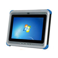
IEI Technology ICEROCK3-T10 User Manual (129 pages)
Industrial Tablet PC
Brand:
IEI Technology
| Category:
Tablet
| Size: 5.71 MB
Table of Contents
Table of Contents
4
User Manual
1
1 Introduction
13
Overview
14
Figure 1-1: ICEROCK3-T10
14
Model Variations
15
Features
15
Table 1-1: Model Variations
15
Front Panel
16
Figure 1-2: Front Panel
16
Figure 1-3: Front Panel LED Indicators
16
Status Indicators
16
Table 1-2: Status Indicators
17
Rear Panel
18
Side Panels
18
Figure 1-4: Rear Panel
18
Figure 1-5: Side Panel
18
Top Panel
19
Bottom Panel
19
Figure 1-6: Top Panel
19
Figure 1-7: Bottom Panel
19
Technical Specifications
20
Table 1-3: Technical Specifications
21
Dimensions
22
Figure 1-8: Dimensions (Units in MM)
22
2 Unpacking
23
Unpacking
24
Packing List
25
Table 2-1: Packing List
25
Table 2-2: Optional Items
26
3 Installation
27
Charge the System
28
Figure 3-1: Install Charging Adapter
28
Figure 3-2: Charge Status LED
29
Figure 3-3: Battery Capacity Indicators
29
Figure 3-4: Windows Embedded 7 Power Management Screen
30
Optional Charging Station
30
Power-Up the System
31
Figure 3-5: Charge the System through Charging Station
31
Figure 3-6: Power Button Location
31
Sd Card Installation
32
Figure 3-7: Install Microsd Card
32
SIM Card Installation (Optional)
33
Using Rfid Reader
33
Figure 3-8: SIM Card Installation
33
Figure 3-9: Pcsctool Location
34
Figure 3-10: NXP PCSC Tool Screen
34
Figure 3-11: NXP PCSC Tool - Mode Selection
35
Figure 3-12: NXP PCSC Tool - Reader Selection
35
Figure 3-13: NXP PCSC Tool - Select the Reader
35
Figure 3-14: NXP PCSC Tool - Read RFID Card
36
Figure 3-15: RFID Reader Location
36
Using Barcode Scanner
37
Figure 3-16: Barcode Scanner Program Location
37
Figure 3-17: Ezconfig-Scanning Installshield Wizard
38
Figure 3-18: Ezconfig-Scanning Window
38
Figure 3-19: Ezconfig-Scanning - Port Settings
39
Figure 3-20: Barcode On/Off Button and Barcode Status Indicator
40
Using Gps Evaluation Software
41
Figure 3-21: Barcode Information Display Area
41
Figure 3-22: GPS Evaluation Software Location
42
Mounting the System
43
Figure 3-23: U-Center Window
43
Figure 3-24: VESA Mount Screw Holes
43
I/O Connectors
44
Audio Connectors (MIC-In and Headphones)
44
Figure 3-25: Left Side I/O Connectors
44
I/O C ONNECTORS 3.9.1 Audio Connectors (MIC-In and Headphones)
44
Figure 3-26: Audio Connectors
45
Micro HDMI Device Connection
45
Figure 3-27: Micro HDMI Device Connection
46
USB Device Connection
46
Using 3-In-1 Combo Reader (Optional)
47
Figure 3-28: USB Device Connection
47
Figure 3-29: 3-In-1 Combo Reader
47
Figure 3-30: Combo Reader Installation
48
Figure 3-31: Secure the Combo Reader
48
4 Driver Installation
50
Available Software Drivers
51
Intel® Chipset Driver
51
Intel® Graphics Driver
52
Figure 4-1: Chipset Driver Location
52
Figure 4-2: Graphics Driver Location
53
Figure 4-3: Intel® Graphics Driver Installshield Wizard
53
G Driver
54
Figure 4-4: 3.75G Driver Location
54
Audio Driver
55
Figure 4-5: 3.75G Driver Installshield Wizard
55
Figure 4-6: Speaker and Microphone Driver Location
56
Figure 4-7: Realtek HD Audio Driver Installshield Wizard
56
Bluetooth Driver
57
Figure 4-8: Bluetooth Driver Location
57
Rfid Driver
58
Figure 4-9: Bluetooth Driver Installshield Wizard
58
Figure 4-10: RFID Driver Folder
59
Figure 4-11: RFID Driver Installation
59
Usb 3.0 Driver
60
Figure 4-12: USB 3.0 Driver Location
60
Wireless Lan Driver
61
Figure 4-13: USB 3.0 Driver Installshield Wizard
61
Figure 4-14: Wireless LAN Driver Location
62
Figure 4-15: Wireless LAN Installshield Wizard
62
SCR Driver (Optional)
63
Figure 4-16: SCR Driver Folder - Usbser.sys
63
Figure 4-17: Device Manager - Update Driver Software
63
Figure 4-18: Update Driver Software Window
64
Figure 4-19: Browse for Driver Software Window
64
Figure 4-20: Installing Driver Window
65
Figure 4-21: Driver Installation Complete Window
65
MSR Driver (Optional)
66
Figure 4-22: Device Manager Window
66
Figure 4-23: MSR Driver Folder - Usbser.sys
66
Figure 4-24: Device Manager - Update Driver Software
67
Figure 4-25: Update Driver Software Window
67
Figure 4-26: Browse for Driver Software Window
68
Figure 4-27: Installing Driver Window
68
Figure 4-28: Driver Installation Complete Window
69
Figure 4-29: Device Manager Window
69
Fingerprint Reader Driver (Optional)
70
Figure 4-30: Fingerprint Reader Driver Folder
70
Figure 4-31: Fingerprint Reader Driver Installshield Wizard
71
5 Bios Setup
72
Introduction
73
Starting Setup
73
Using Setup
73
BIOS Menu Bar
74
Getting Help
74
Table 5-1: BIOS Navigation Keys
74
Main
75
BIOS Menu 1: Main
75
Advanced
76
System Date [XX/XX/XX]
76
System Time [XX:XX:XX]
76
ACPI Settings
77
BIOS Menu 2: Advanced
77
BIOS Menu 3: ACPI Configuration
77
RTC Wake Settings
78
BIOS Menu 4: RTC Wake Settings
78
ACPI Sleep State [S3 Only (Suspend to RAM)]
78
Wake System with Fixed Time [Disabled]
78
Trusted Computing
80
BIOS Menu 5: Trusted Computing
80
Security Device Support [Disable]
80
CPU Configuration
81
BIOS Menu 6: CPU Configuration
81
Hyper Threading [Enabled]
82
Intel Virtualization Technology [Disabled]
82
SATA Configuration
83
BIOS Menu 7: SATA Configuration
83
SATA Controller(S) [Enabled]
83
SATA Mode Selection [IDE]
83
Intel(R) Rapid Start Technology
84
BIOS Menu 8: Intel(R) Rapid Start Technology
84
USB Configuration
85
BIOS Menu 9: USB Configuration
85
Legacy USB Support [Enabled]
85
USB Devices
85
Iwdd Serial Ports Configuration
86
BIOS Menu 10: Iwdd Super IO Configuration
86
Serial Port N Configuration
87
BIOS Menu 11: Serial Port 1 Configuration Menu
87
Change Settings [Auto]
87
Serial Port [Enabled]
87
Change Settings [Auto]
88
Serial Port [Enabled]
88
H/W Monitor
89
BIOS Menu 12: Hardware Health Configuration
89
PC Health Status
89
IEI Feature
90
BIOS Menu 13: IEI Feature
90
Auto Recovery Function [Disabled]
90
Chipset
91
BIOS Menu 14: Chipset
91
PCH-IO Configuration
92
BIOS Menu 15: Host Bridge Chipset Configuration
92
Azalia Internal HDMI Codec [Enabled]
92
Camera Function (Back, CAMERA1) [Enabled]
92
Camera Function(Front, CAMERA2) [Enabled]
92
Barcode Function [Disabled]
93
GPS Function [Enabled]
93
Micro-SD Function [Enabled]
93
Bluetooth Function [Enabled]
94
LCD ECO Mode Function [Disabled]
94
Radio Function [Enabled]
94
WIFI Radio Function [Enabled]
94
Windows Rotation Function [Disabled]
94
System Agent (SA) Configuration
95
BIOS Menu 16: System Agent (SA) Configuration
95
VT-D [Disabled]
95
Graphics Configuration
96
BIOS Menu 17: Graphics Configuration
96
DVMT Pre-Allocated [256M]
96
DVMT Total Gfx Mem [MAX]
96
Primary Display [Auto]
96
Primary IGFX Boot Display [VBIOS Default]
96
Boot
98
Memory Configuration
98
BIOS Menu 18: Memory Configuration
98
BIOS Menu 19: Boot
98
Boot Option #1 [SATA PM: MRMAJ5A03
98
Bootup Numlock State [On]
98
Hard Drive BBS Priorities
98
Option ROM Messages [Force BIOS]
98
Quiet Boot [Enabled]
98
UEFI Boot [Disabled]
98
Security
100
BIOS Menu 20: Security
100
Administrator Password
100
User Password
100
Exit
101
BIOS Menu 21:Exit
101
Discard Changes and Reset
101
Restore Defaults
101
Save as User Defaults
101
Save Changes and Reset
101
Restore User Defaults
102
6 System Maintenance
103
System Maintenance Introduction
104
Motherboard Replacement
104
Battery Replacement
104
Figure 6-1: Unlock Battery Latches
104
Figure 6-2: Battery Installation
105
A Regulatory Compliance
106
B Safety Precautions
111
General Safety Precautions
112
Safety Precautions
112
Anti-Static Precautions
113
Maintenance and Cleaning
114
Maintenance and Cleaning Precautions
114
Product Disposal
114
Cleaning Tools
115
CBIOS Options
116
Appendix C
117
D Terminology
119
E Watchdog Timer
123
F Hazardous Materials Disclosure
126
Hazardous Materials Disclosure Table for IPB Products Certified as Rohs Compliant under 2002/95/EC Without Mercury
127
Advertisement
IEI Technology ICEROCK3-T10 User Manual (111 pages)
Industrial Tablet PC Intel Core i7 CPU, 8 GB DDR3 SDRAM, USB 3.0, Micro HDMI, microSD Slot, 802.11b/g/n Wireless, RFID, Barcode Scanner, Mobile 3.75G, IP 65, RoHS Compliant
Brand:
IEI Technology
| Category:
Tablet
| Size: 5.18 MB
Table of Contents
Table of Contents
4
User Manual
1
1 Introduction
11
Overview
12
Figure 1-1: ICEROCK3-T10
12
Model Variations
13
Features
13
Table 1-1: Model Variations
13
Front Panel
14
Figure 1-2: Front Panel
14
Figure 1-3: Front Panel LED Indicators
14
Status Indicators
14
Table 1-2: Status Indicators
15
Rear Panel
16
Side Panels
16
Figure 1-4: Rear Panel
16
Figure 1-5: Side Panel
16
Top Panel
17
Bottom Panel
17
Figure 1-6: Top Panel
17
Figure 1-7: Bottom Panel
17
Technical Specifications
18
Table 1-3: Technical Specifications
19
Dimensions
20
Figure 1-8: Dimensions (Units in MM)
20
2 Unpacking
21
Unpacking
22
Packing List
23
Table 2-1: Packing List
23
Table 2-2: Optional Items
24
3 Installation
25
Charge the System
26
Figure 3-1: Install Charging Adapter
26
Figure 3-2: Charge Status LED
27
Figure 3-3: Battery Capacity Indicators
27
Figure 3-4: Windows Embedded 7 Power Management Screen
28
Optional Charging Station
28
Power-Up the System
29
Figure 3-5: Charge the System through Charging Station
29
Figure 3-6: Power Button Location
29
Sd Card Installation
30
Figure 3-7: Install Microsd Card
30
SIM Card Installation (Optional)
31
Using Rfid Reader
31
Figure 3-8: SIM Card Installation
31
Figure 3-9: Pcsctool Location
32
Figure 3-10: NXP PCSC Tool Screen
32
Figure 3-11: NXP PCSC Tool - Mode Selection
33
Figure 3-12: NXP PCSC Tool - Reader Selection
33
Figure 3-13: NXP PCSC Tool - Select the Reader
33
Figure 3-14: NXP PCSC Tool - Read RFID Card
34
Figure 3-15: RFID Reader Location
34
Using Barcode Scanner
35
Figure 3-16: Barcode Scanner Program Location
35
Figure 3-17: Ezconfig-Scanning Installshield Wizard
36
Figure 3-18: Ezconfig-Scanning Window
36
Figure 3-19: Ezconfig-Scanning - Port Settings
37
Figure 3-20: Barcode On/Off Button and Barcode Status Indicator
38
Using Gps Evaluation Software
39
Figure 3-21: Barcode Information Display Area
39
Figure 3-22: GPS Evaluation Software Location
40
Mounting the System
41
Figure 3-23: U-Center Window
41
Figure 3-24: VESA Mount Screw Holes
41
I/O Connectors
42
Audio Connectors (MIC-In and Headphones)
42
Figure 3-25: Left Side I/O Connectors
42
I/O C ONNECTORS 3.9.1 Audio Connectors (MIC-In and Headphones)
42
Figure 3-26: Audio Connectors
43
Micro HDMI Device Connection
43
Figure 3-27: Micro HDMI Device Connection
44
USB Device Connection
44
Figure 3-28: USB Device Connection
45
4 Driver Installation
46
Available Software Drivers
47
Intel® Chipset Driver
47
Intel® Graphics Driver
48
Figure 4-1: Chipset Driver Location
48
Figure 4-2: Graphics Driver Location
49
Figure 4-3: Intel® Graphics Driver Installshield Wizard
49
G Driver
50
Figure 4-4: 3.75G Driver Location
50
Audio Driver
51
Figure 4-5: 3.75G Driver Installshield Wizard
51
Figure 4-6: Speaker and Microphone Driver Location
52
Figure 4-7: Realtek HD Audio Driver Installshield Wizard
52
Bluetooth Driver
53
Figure 4-8: Bluetooth Driver Location
53
Rfid Driver
54
Figure 4-9: Bluetooth Driver Installshield Wizard
54
Figure 4-10: RFID Driver Folder
55
Figure 4-11: RFID Driver Installation
55
Usb 3.0 Driver
56
Figure 4-12: USB 3.0 Driver Location
56
Wireless Lan Driver
57
Figure 4-13: USB 3.0 Driver Installshield Wizard
57
Figure 4-14: Wireless LAN Driver Location
58
Figure 4-15: Wireless LAN Installshield Wizard
58
5 Bios Setup
59
Introduction
60
Starting Setup
60
Using Setup
60
BIOS Menu Bar
61
Getting Help
61
Table 5-1: BIOS Navigation Keys
61
Main
62
BIOS Menu 1: Main
62
Advanced
63
System Date [XX/XX/XX]
63
System Time [XX:XX:XX]
63
ACPI Settings
64
BIOS Menu 2: Advanced
64
BIOS Menu 3: ACPI Configuration
64
RTC Wake Settings
65
BIOS Menu 4: RTC Wake Settings
65
ACPI Sleep State [S3 Only (Suspend to RAM)]
65
Wake System with Fixed Time [Disabled]
65
Trusted Computing
67
BIOS Menu 5: Trusted Computing
67
Security Device Support [Disable]
67
CPU Configuration
68
BIOS Menu 6: CPU Configuration
68
Hyper Threading [Enabled]
69
Intel Virtualization Technology [Disabled]
69
SATA Configuration
70
BIOS Menu 7: SATA Configuration
70
SATA Controller(S) [Enabled]
70
SATA Mode Selection [IDE]
70
Intel(R) Rapid Start Technology
71
BIOS Menu 8: Intel(R) Rapid Start Technology
71
USB Configuration
72
BIOS Menu 9: USB Configuration
72
Legacy USB Support [Enabled]
72
USB Devices
72
Iwdd Serial Ports Configuration
73
BIOS Menu 10: Iwdd Super IO Configuration
73
Serial Port N Configuration
74
BIOS Menu 11: Serial Port 1 Configuration Menu
74
Change Settings [Auto]
74
Serial Port [Enabled]
74
Change Settings [Auto]
75
Serial Port [Enabled]
75
H/W Monitor
76
BIOS Menu 12: Hardware Health Configuration
76
PC Health Status
76
IEI Feature
77
BIOS Menu 13: IEI Feature
77
Auto Recovery Function [Disabled]
77
Chipset
78
BIOS Menu 14: Chipset
78
PCH-IO Configuration
79
BIOS Menu 15: Host Bridge Chipset Configuration
79
Azalia Internal HDMI Codec [Enabled]
79
Camera Function (Back, CAMERA1) [Enabled]
79
Camera Function(Front, CAMERA2) [Enabled]
79
Barcode Function [Disabled]
80
GPS Function [Enabled]
80
Micro-SD Function [Enabled]
80
Bluetooth Function [Enabled]
81
LCD ECO Mode Function [Disabled]
81
Radio Function [Enabled]
81
WIFI Radio Function [Enabled]
81
Windows Rotation Function [Disabled]
81
System Agent (SA) Configuration
82
BIOS Menu 16: System Agent (SA) Configuration
82
VT-D [Disabled]
82
Graphics Configuration
83
BIOS Menu 17: Graphics Configuration
83
DVMT Pre-Allocated [256M]
83
DVMT Total Gfx Mem [MAX]
83
Primary Display [Auto]
83
Primary IGFX Boot Display [VBIOS Default]
83
Boot
85
Memory Configuration
85
BIOS Menu 18: Memory Configuration
85
BIOS Menu 19: Boot
85
Boot Option #1 [SATA PM: MRMAJ5A03
85
Bootup Numlock State [On]
85
Hard Drive BBS Priorities
85
Option ROM Messages [Force BIOS]
85
Quiet Boot [Enabled]
85
UEFI Boot [Disabled]
85
Security
87
BIOS Menu 20: Security
87
Administrator Password
87
User Password
87
Exit
88
BIOS Menu 21:Exit
88
Discard Changes and Reset
88
Restore Defaults
88
Save as User Defaults
88
Save Changes and Reset
88
Restore User Defaults
89
6 System Maintenance
90
System Maintenance Introduction
91
Motherboard Replacement
91
Battery Replacement
91
Figure 6-1: Unlock Battery Latches
91
Figure 6-2: Battery Installation
92
A Safety Precautions
93
General Safety Precautions
94
Safety Precautions
94
Anti-Static Precautions
95
Maintenance and Cleaning
96
Maintenance and Cleaning Precautions
96
Product Disposal
96
Cleaning Tools
97
BBIOS Options
98
Appendix B
99
C Terminology
101
D Watchdog Timer
105
E Hazardous Materials Disclosure
108
Hazardous Materials Disclosure Table for IPB Products Certified as Rohs Compliant under 2002/95/EC Without Mercury
109
Advertisement
Related Products
IEI Technology ICEROCK-08A Series
IEI Technology ICEROCK-08A-Z530
IEI Technology ICEROCK-08A-Z510
IEI Technology IceCare-10W series
IEI Technology ICELOG-07
IEI Technology ICEFIRE-T10A
IEI Technology ICECARE-05-HF-R10
IEI Technology ICECARE-05-ET-R10
IEI Technology ICECARE-05-UHF-R10
IEI Technology ICE-BT-T10-E38251
IEI Technology Categories
Motherboard
Touch Panel
Computer Hardware
Single board computers
Desktop
More IEI Technology Manuals
Login
Sign In
OR
Sign in with Facebook
Sign in with Google
Upload manual
Upload from disk
Upload from URL