Table of Contents
Advertisement
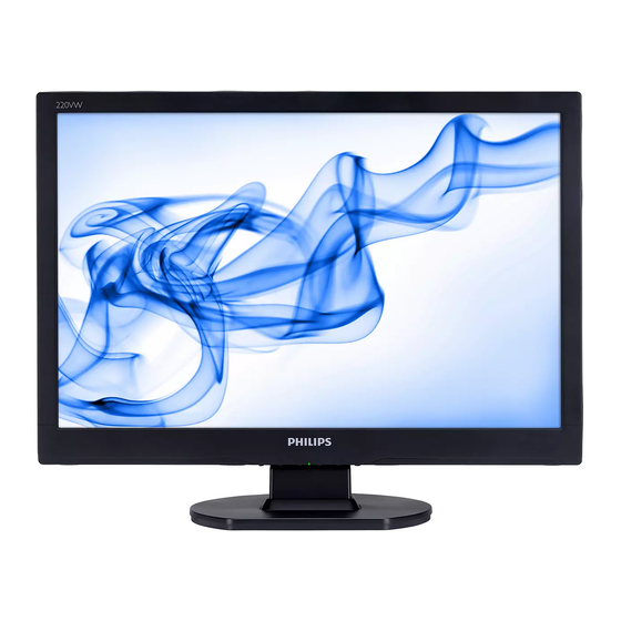
22" LCD Color Monitor
Service
Service
Service
Description
Table Of Contents.....................................................1
Revision List........................................................2
Important Safety Notice.............................................3
1. Monitor Specifications..............................................4
2. LCD Monitor Description..........................................6
3.1General Instructions........................................7
3.2 Control buttons...............................................7
3.3 Adjusting the Picture...............................................9
3.4 Connecting to the PC ........................................11
4. Input/Output Specification......................................12
4.1 Input Signal Connector.........................................12
4.2 Factory Preset Display Modes...............................12
4.3 Pixel Defect Policy..........................................13
4.4 Failure Mode Of Panel ....................................16
5. Block Diagram.................................................17
5.1 Software Flow Chart.............................................17
5.2 Electrical Block Diagram....................................19
6. Schematic Diagram.............................................21
ANY PERSON ATTEMPTING TO SERVICE THIS CHASSIS MUST FAMILIARIZE HIMSELF WITH THE
CHASSIS AND BE AWARE OF THE NECESSARY SAFETY PRECAUTIONS TO BE USED WHEN
SERVICING ELECTRONIC EQUIPMENT CONTAINING HIGH VOLTAGES.
CAUTION: USE A SEPARATE ISOLATION TRANSFOMER FOR THIS UNIT WHEN SERVICING
REFER TO BACK COVER FOR IMPORTANT SAFETY GUIDELINES
Copyright 2008 Philips Consumer Lifestyle
220VW9FB/97
220VW9FB/62
220VW9FB/27
220VW9FB/05
220VW9FB/00
220VW9FB/93
220VW9FB/75
220VW9FB/94
Page
Description
6.1 Main Board.................................................21
6.2 Power Board...............................................26
6.3 Key Board...................................................28
7. PCB Layout........................................................29
7.1 Main Board........................................................29
7.2 Power Board......................................................31
7.3 Key Board...................................................33
8. Wiring Diagram................................................34
9. Scalar Board Overview.....................................35
10. Mechanical Instructions......................................36
11.Trouble shooting...........................................41
12. Repair Flow Chart.........................................43
13. ISP Instructions....................................................49
14. DDC Instructions................................................57
15. White Balance, Luminance Adjustment.................66
16. Monitor Exploded View......................................68
17. Recommended & Spare Parts List.........................69
18. Different Parts List.............................................71
19. General Product Specification..........................73
SAFETY NOTICE
Subject to modification ○
K
Chassis: HUDSON 9
GB
Apr, 10, 2008
3122 785 17840
Page
Advertisement
Chapters
Table of Contents

Related Manuals for Philips 220VW9FB/97


Summary of Contents for Philips 220VW9FB/97
-
Page 1: Table Of Contents
SERVICING ELECTRONIC EQUIPMENT CONTAINING HIGH VOLTAGES. CAUTION: USE A SEPARATE ISOLATION TRANSFOMER FOR THIS UNIT WHEN SERVICING REFER TO BACK COVER FOR IMPORTANT SAFETY GUIDELINES Copyright 2008 Philips Consumer Lifestyle Subject to modification ○ Apr, 10, 2008 3122 785 17840... -
Page 2: Revision List
Add Philips 12NC for 220VW9FB/97 Apr.25, 2008 Add CTV Model 220VW9FB/93 and 220VW9FB/75 in Item18 Apr.30, 2008 Add CTV Model 220VW9FB/94 in Item18 May.07, 2008 Perfect Philips 12NC for 220VW9FB/75 and 220VW9FB/93 May.15, 2008 Add a new power cord 089G404A15N YH for 220VW9FB/97... -
Page 3: Important Safety Notice
HUDSON 9 Important Safety Notice Proper service and repair is important to the safe, reliable operation of all Philips Company Equipment. The service procedures recommended by Philips and described in this service manual are effective methods of performing service operations. Some of these service operations require the use of tools specially designed for the purpose. -
Page 4: Monitor Specifications
HUDSON 9 1. Monitor Specifications... - Page 5 HUDSON 9...
-
Page 6: Lcd Monitor Description
HUDSON 9 2. LCD Monitor Description The LCD monitor will contain a main board, a power board and a key board which house the flat panel control logic, brightness control logic and DDC. The power board will provide AC to DC Inverter voltage to drive the backlight of panel and the main board chips each voltage. -
Page 7: Operating Instructions
HUDSON 9 3. Operating Instructions 3.1 General Instructions Press the power button to turn the monitor on or off. The other control buttons are located at the front of the panel of the monitor. By changing these settings, the picture can be adjusted to your personal preferences. The power cord should be connected. - Page 8 HUDSON 9 Rear View...
-
Page 9: Adjusting The Picture
HUDSON 9 3.3 Adjusting the Picture Description of the On Screen Display When you press the button on the front control of your monitor, the On-Screen Display (OSD) Main Controls window will pop up and you can then start making adjustments to your monitor's various features. Use the keys to make your adjustments. - Page 10 HUDSON 9 The OSD Tree Below is an overall view of the structure of the On-Screen Display. You can use this as a reference when you want to work your way around the different adjustments later on.
-
Page 11: Connecting To The Pc
HUDSON 9 3.4 Connecting to the PC 1) Connect the power cord to the back of the monitor firmly. 2) Connect to PC (a) Turn off your computer and unplug its power cable. (b) Connect the monitor signal cable to the video connector on the back of your computer. (c) Plug the power cord of your computer and your monitor into a nearby outlet. -
Page 12: Input/Output Specification
7 . G r e e n v i d e o g r o u n d 1 5 . D a t a c l o c k l i n e ( S C L ) 8 . B l u e v i d e o g r o u n d V G A c o n n e c t o r l a y o u t HUDSON 9 4 . -
Page 13: Pixel Defect Policy
HUDSON 9 4.3 Pixel Defect Policy... - Page 14 HUDSON 9...
- Page 15 HUDSON 9...
-
Page 16: Failure Mode Of Panel
HUDSON 9 4.4 Failure Mode Of Panel Quick reference for failure mode of LCD panel this page presents problems that could be made by LCD panel. It is not necessary to repair circuit board. Simply follow the mechanical Polarizer has bubbles instruction on this manual to eliminate failure by replace LCD panel. -
Page 17: Block Diagram
HUDSON 9 5. Block Diagram 5.1 Software Flow Chat... - Page 18 HUDSON 9 1) MCU initialize. 2) Is the EPROM blank? 3) Program the EPROM by default values. 4) Get the PWM value of brightness from EPROM. 5) Is the power key pressed? 6) Clear all global flags. 7) Are the AUTO and SELECT keys pressed? 8) Enter factory mode.
-
Page 19: Electrical Block Diagram
HUDSON 9 5.2 Electrical Block Diagram 5.2.1 Main Board Panel Interface (CN403) Scalar TSUMU18ER-LF EEPROM Keypad Interface (Include MCU, ADC, OSD) M24C16 (CN401) (U401) (U403) H sync V sync Flash Memory Crystal SST25VF010A-33-4C-SAE 14.31818MHZ (U402) (X401) D-Sub Connector (CN101) VGA_R+, VGA_SDA, VGA_G+, VGA_SCL... - Page 20 HUDSON 9 5.2.2 Inverter/Power Board AC input Bridge Rectifier Transformer Rectifier diodes EMI filter and Filter Start Circuit: R904、R905、R906 Feedback Circuit Control IC ON/OFF Output MOSFET Circuit Transformer Lamp Over ON/OFF Feedback Voltage Control Circuit Control IC...
-
Page 21: Schematic Diagram
HUDSON 9 6. Schematic 6.1 Main Board 715G2904-1-5 TSUM16FWR SCHEMATIC XGA/SXGA LVDS OUTPUT DSUB_R+ DSUB_R+ VCC1.8 DSUB_R- DSUB_R- DSUB_G+ DSUB_G+ VCC3.3 DSUB_G- DSUB_G- VCC1.8 DSUB_SOG DSUB_SOG CMVCC DSUB_B+ DSUB_B+ DSUB_5V DSUB_B- DSUB_B- VCC3.3 CMVCC1 DSUB_H DSUB_H CMVCC1 DSUB_V DSUB_V DSUB_5V DDC1_SDA DDC1_SDA CMVCC... - Page 22 HUDSON 9 INPUT C101 D2 C102 D4 H_Sync R101 0R05 1/10W 5% R102 100R 1/16W 5% DSUB_H C103 D3 V_Sync R103 100R 1/16W 5% FB102 DSUB_V C104 D2 R104 C101 VGA_B+ C105 D2 DSUB_B+ VCC3.3 R105 R106 C102 C103 BEAD C106 C2 2K2 1/16W 5% 2K2 1/16W 5%...
- Page 23 HUDSON 9 SCALAR VDDP VDDC AVDD C433 0.1uF/16V C401 C4 C403 D2 VCC3.3 VDDP FB401 AVDD C404 D2 C406 D2 U401 VCC3.3 C407 D2 300OHM VCTRL C408 C5 VCTRL C403 C404 C409 C1 LVA3P 0.1uF/16V 0.1uF/16V C410 C5 DSUB_R+ RIN0P LVA3M C411 C5 DSUB_R-...
- Page 24 HUDSON 9 OUTPUT PANEL_VCC CN403 PA[0..1] PB[0..9] PA[0..1] PB[0..9] R434 C420 PA[4..9] PA[4..9] 330 OHM 1/4W 0.1uF/16V CMVCC AO3401L CMVCC R433 C419 R435 10K 1/16W 5% 0.1uF/16V PANEL_VCC 4K7 1/16W 5% Q405 AO3401 C419 B4 R436 FB402 CONN C420 D2 100K 1/16W 5% C421 B3 PPWR_ON#...
- Page 25 HUDSON 9 POWER ESD_VCC 2 DSUB_5V CMVCC DSUB_5V 2 D403 5, 6 CMVCC VCC3.3 R460 VCC3.3 VCC3.3 D401 3.3 OHM 2W BAV99 CN404 R461 R437 R439 CMVCC1 SM340A D402 10K 1/16W 5% 10K 1/16W 5% CMVCC CMVCC1 VCC1.8 CMVCC BKLT-EN Q410 BKLT-VBRI R450...
-
Page 26: Power Board
HUDSON 9 6.2 Power Board 715G2824-1 POWER BD901 D5 BD901 B4 C900 B3 C901 B5 C902 B5 C903 B5 C904 C5 R918 C905A C5 100R 1/4W C906 C4 C912 L904 C907 C4 R919 0.001uF 100R 1/4W C908 C4 +16V C909 B4 R920 C912 D2 BD901... - Page 27 HUDSON 9 INVERTER C819 CN801 68pF3KV +16V R805 C820 ON/OFF 100R 1/10W 68pF3KV D801 PT801 Q805 POWER X'FMR CN802 1N4148W L801 R806 C802 C4 C801 C4 C816 C803 B5 C804 B5 100R 1/8W 22pF/6KV C807 B4 C805 B5 ZD802 D802 ZD803 R804 C809 B3 C806 C5...
-
Page 28: Key Board
HUDSON 9 6.3 Key Board 715G2836-1-2 LED_RED# LED_GRN# D001 CN001 R001 4.3K OHM 1/8W LBADC1 R002 2K4 1/8W LBADC2 DC_POWERON R003 910R 1/8W LED_GRN# LED_RED# R004 4.3K OHM 1/8W C001 C002 C003 C004 C005 R005 2K4 1/8W NC/0.001uF NC/0.001uF NC/0.001uF NC/0.001uF NC/0.001uF CONN... -
Page 29: Pcb Layout
HUDSON 9 7. PCB Layout 7.1 Main Board 715G2904-1-5 C101 C3 R111 C3 ZD104 R108 C103 C3 R113 C102 R110 C105 C3 R115 C104 R112 C107 C3 R117 C106 R114 C109 C3 R120 C108 R116 C111 C3 R401 C110 R118 C114 D3 R403 C113... - Page 30 HUDSON 9...
-
Page 31: Power Board
HUDSON 9 7.2 Power Board 715G2824-1 BD901 D3 J821 BD901A D3 J823 BD901B D3 J824 C604 J825 C812 J826 C816 J829 C817 J830 C819 J831 C820 J832 C821 J833 C822 J834 C824 J835 C900 J836 C901 J837 C902 J838 C903 J901 C905 J902... - Page 32 HUDSON 9 C601 R818 D805 R926 C602 R819 D806 R927 C603 R820 D807 R930 C606 R821 D808 R935 C608 R822 D809 R938 C609 R823 D903 R939 C610 R824 FB902 C3 R940 C611 R825 IC801 B2 R942 C612 R826 IC901 C3 R943 C613 R827...
-
Page 33: Key Board
HUDSON 9 7.3 Key Board 715G2836-1-2 CN001 A4 D001 GND1 GND2 SW001 A1 SW002 A2 SW003 A1 SW004 A3 SW005 A3 SW006 A4 C001 C005 C006 C007 C005 C006 C007 C008 C009 C010 C011 R003 R004 R005 R003 R004 R005 R006 ZD001 A1 ZD002 A3... -
Page 34: Wiring Diagram
HUDSON 9 8. Wiring Diagram Panel 89G179E30N520 FFC Cable 30 Pin CN403 CN902 CN802 CN801 Power Board Main Board CN404 TSUM1PFR-LF U401 CN804 CN401 AC IN CN803 CN101 CN901 D-SUB 6 Pin Key Board CN001... -
Page 35: Scalar Board Overview
HUDSON 9 9. Scalar Board Overview DC-DC Converters DC-DC Converters D-SUB Morning Star chip D-SUB Flash ROM EEPROM... -
Page 36: Mechanical Instructions
HUDSON 9 10. Mechanical Instructions 1. Back View as Fig1 Place the monitor face down on a smooth surface as Fig 1. Be careful to avoid scratch and injury during the uninstallation. Fig1 2. Remove the hinge as Fig2. Remove the three screws remarked in red to remove the hinge as Fig2. Fig2... - Page 37 3. Remove rear cover as Fig3~Fig7. Fig3 Fig4 Fig5...
- Page 38 HUDSON 9 Fig6 Fig7 4. Remove the bezel as Fig8. Pull out the key board from the bezel Fig8...
- Page 39 5. Remove main frame cover as Fig9~Fig10. a. Remove the two screws marked in red as Fig9. b. Disconnect the four connector marked in blue as Fig9. c. Remove the two screws marked in red as Fig10. Fig9 Fig10 6. Remove power board as Fig11. a.
- Page 40 HUDSON 9 7. Remove scalar board as Fig12~Fig13. a. Remove the screw remarked in red as Fig12. b. Disconnect the two connectors marked in blue as Fig12. c. Remove the two screws remarked in red as Fig13. Fig12 Fig13...
-
Page 41: Trouble Shooting
11. Trouble Shooting This page deals with problems that can be corrected by a user. If the problem still persists after you have tried these solutions, contact Philips customer service representative. - Page 42 HUDSON 9...
-
Page 43: Repair Flow Chart
12. Repair Flow Chart 12.1 Main Board (1). No Power No power Press power key and look if the picture is normal Please reinsert and make sure the AC of 100-240 is normal Reinsert or check the Adapter/Inverter section Measure U404 PIN2=3.3V Q409 V =1.8V collector... - Page 44 HUDSON 9 (2). No Picture No picture The button if X401 oscillate Replace X401 under control waveform is normal Check reset circuit of Check Correspondent component U401 is normal Measure U404 PIN2=3.3V Q409 V =1.8V collector Replace U401 Check U404, Q409 and Q410 X401 oscillate waveform is normal Replace X401...
- Page 45 (3). White screen White screen Measure Q404 base X401 oscillate waveform is normal is low level? Replace X401 Check Q404, Q405 is broken or CN403 solder? Check reset circuit of U401 is normal Check Correspondent Check Correspondent component. component. Replace Panel Replace U401...
- Page 46 HUDSON 9 11.2. Power/Inverter Board (1) No power Check ZD902 (-) = 16V Check AC line volt 110V or 220V Check AC input Check the voltage of C905 (+) Check bridge rectified circuit and F901 circuit Check start voltage for the pin3 of IC901 Check R904, R905, R906 and Change IC901 Check the auxiliary voltage is bigger than 10V and smaller than 20V...
- Page 47 (2) W / LED, No Backlight Check CN902 pin4 = 16V Check adapter or MB Check ON/OFF signal Check Interface board Check IC801 PIN2=5V Check Q801 and ZD801 Check IC801 PIN1, 15 have the output of square wave at short Change IC801 Check Q805 and Q806 PIN5, 6, 7, 8 have the output of square wave at short time.
- Page 48 HUDSON 9 12.3 Key Board OSD is unstable or not working Is Key Pad Board connecting normally? Connect Key Pad Board Replace Button Switch Is Button Switch normally? Replace Key Pad Board Is Key Pad Board normally? Check Main Board...
-
Page 49: Isp Instruction
13. ISP Instruction 1. When do the part, need the tools as follow: a. An i486 (or above) personal computer or compatible. b. Microsoft operation system Windows 95/98/2000/XP. c. “ PORT95NT.exe” program d. Software ISP SN Alignment kits The kit contents: a. - Page 50 HUDSON 9...
- Page 52 HUDSON 9 Click to complete the installation.
- Page 53 Note: After installation, you must restart the PC to take the setup to effect. 3. Connect the ISP board as follow: Connect to Connect to the the PC LPT Philips 220VW9...
- Page 54 HUDSON 9 4. The process of ISP write is as follows. a. Double-click ,running the program as follows:...
- Page 55 b. Click icon, search the program” 220VW9_TSUMU18ER_CLAA220WA01_20080331_V101”, and click open:...
- Page 56 HUDSON 9 c. Click icon, it will auto run. If burn in success, it will show as the follow picture:...
-
Page 57: Ddc Instruction
14. DDC Instruction General DDC Data Re-programming In case the main EEPROM with Software DDC which store all factory settings were replaced because a defect, repaired monitor’ the serial numbers have to be re-programmed. It is advised to re- soldered the main EEPROM with Software DDC from the old board onto the new board if circuit board have been replaced, in this case the DDC data does not need to be re-programmed. - Page 58 HUDSON 9 2. Install the “WinDDC_ setup” Second, you must install the . The processing as follows:...
- Page 60 HUDSON 9 Click to complete the installation. 3. Connect the DDC board as follow: Connect to the PC LPT When you write analog EDID, Connect this port to the Philips 220VW9’s VGA port 12V Input...
- Page 61 4. Take analog DDC write for example, as follow a. Double-click ,appear as follow Figs:...
- Page 62 HUDSON 9 b. Click , then click “OK”. It will appear as follow. c. Double-click , appear as follow Figs:...
- Page 63 d. Key “1”, press “Enter” key, and key 14 numbers after “Input Serial Number” as follow, e. Now analog DDC Write completes, as bellow,...
- Page 64 HUDSON 9 220VW9 EDID Analog 128 bytes EDID Data (Hex): x0 x1 x2 x3 x4 x5 x6 x7 x8 x9 xA xB xC xD xE xF 00 FF FF FF FF FF FF 00 41 0C 22 C0 F8 C3 04 00 10: 15 0D 01 03 0E 2E 1E 78 2A 85 C5 A4 55 4A 9C 24 20: 14 50 54 BF EF 80 71 4A 71 4F 81 40 81 80 B3 00 30: 01 01 01 01 01 01 21 39 90 30 62 1A 27 40 68 B0...
- Page 65 Detailed Timing: FF (Monitor SN) '123132131231' Detailed Timing: FD (Monitor limits) Min. V. rate: 56Hz Max. V. rate: 76Hz Min. H. rate: 30KHz Max. H. rate: 83KHz Max. Pixel Clock: 170MHz Detailed Timing: FC (Monitor Name) 'Philips 220VW' <-x-Detailed Timing Descriptions-x-> Extension Flag: Checksum:...
-
Page 66: White Balance, Luminance Adjustment
HUDSON 9 15. White Balance, Luminance Adjustment 1. Apparatuses and program: analyzer CA-210, PC, tool, FGA adjustment program (PHILIPS170V9.DDCI), Pattern generator. 2. Equipment installation: a. Connect analyzer CA-210 to PC by USB connector, install drive program CA-SDK Ver4.00 for CA-210 and restart PC after finish installing. - Page 67 4. Color Temp confirmation Connect the signal to the monitor, the monitor display white-picture, use CA-210 to measure the Color Temp of the screen center and select the OSD to make sure whether the Color Temps accord with the SPEC.
-
Page 68: Monitor Exploded View
HUDSON 9 16. Monitor Exploded View... -
Page 69: Recommended & Spare Parts List
FFC CABLE E08901 996510015663 089G404A15N IS POWER CORD E08901 996510017347 089G404A15N YH POWER CORD FQ202 996510015670 Q44GC047813 2A 22 LCD PHILIPS CARTON FQ203 996510010007 P45G 88609 37 EPE BAG FQ205 996510015669 705GQ8CS005 CUSHION ASSY FQ204 996520033961 Q70G2201813 1A CD MANUAL... - Page 70 IC801 996500036059 056G 608 10 IC OZ9938GN-B SOIC-16 IC904 996500036054 056G 158 12 KIA431A-AT/P TO-92 Service Kit Description Philips 12NC PCM Codes Remark DDC KIT 9965 000 43197 715L2005C2 FOR ALL MODEL OSD SN KIT 9965 000 43252 715GT033 C...
-
Page 71: Different Part List
Philips 12NC PCM Codes Description FQ205 705GQ834005 CUSHION ASSY 996510015669 705GQ8CS005 CUSHION ASSY The BOM of 220VW9FB/00 is the same as 220VW9FB/97. Diversity of 220VW9FB/75 compared with 220VW9FB/97 220VW9FB/75 220VW9FB/97 Location Philips 12NC PCM Codes Description Philips 12NC PCM Codes... - Page 72 HUDSON 9 Diversity of 220VW9FB/93 compared with 220VW9FB/97 220VW9FB/93 220VW9FB/97 Location Philips 12NC PCM Codes Description Philips 12NC PCM Codes Description E08901 996510015859 089G414A15N IS POWER CORD 996510015663 089G404A15N IS POWER CORD FQ106 996510016679 A34G0752ADTD1B0130 BEZEL(22") 996510015667 A34G0752ADTC1B0130 BEZEL 22"...
-
Page 73: General Product Specification
PROE FILES REQUIRED 5.3 LOCATION OF PHILIPS LOGO PER PHILIPS MAKE-UP SHEET 5.4 GAP BETWEEN PANEL AND FRONT BEZEL 1.2MM 5.5 LOCATION OF CONTROL ICONS- PER PHILIPS GRAPHIC SHEET 5.6 COLOR FOR RESIN/PAINT PER PHILIPS MAKE-UP SHEET 5.7 RESINS 5.8 IF RAINT IS USED 5.9 PLASITIC MOLD TOOLING... - Page 74 6.3 DISPLAY DISTURBANCES FROM EXTERNAL ENVIRONMENT 6.4 DISPLAY DISTURBANCES TO EXTERNAL ENVIRONMENT RELIABILITY 7.1 MEAN TIME BETWEEN FAILURES QUALITY ASSURANCE REQUIREMENTS 8.1 ACCEPTANCE TEST PHILIPS’ FLAT PANEL MONITORS PIXEL DEFECT POLICY 10. REGULATORY COMPLIANCE 10.1 WORLDWIDE REGULATORY 10.2 EMC REQUIREMENTS 10.3 ROHS 10.4 WEEE...
-
Page 75: Foreword
30 minutes that brightness stability is optimal, and follow strictly after panel specification. 2. PRODUCT PROFILE This display monitor unit is a color display monitor enclosed in PHILIPS styling cabinet which has an integrated tilt base. 2.1 LCD Priority : 1. -
Page 76: Interface Signals
HUDSON 9 3.1 Interface signals 1). D-Sub Analog Input signal: Video, Hsync., Vsync Video: 0.7 Vp-p, input impedance, 75 ohm @DC Sync.: Separate sync TTL level , input impedance 2.2k ohm terminate Hsync Positive/Negative Vsync Positive/Negative Composite sync TTL level, input impedance 2.2k ohm terminate (Positive/Negative) Sync on green video 0.3 Vp-p Negative (Video 0.7 Vp-p Positive) 3.1.1 D-Sub Cable... - Page 77 HUDSON 9 3.2.1 Factory preset modes (12 modes) Factory modes and preset modes are defined in the enclosed timing table file Sync. On Green is request. Detail timing data, Pixel Rate Horizontal Vertical V_Total Polarity Resolution ( MHz ) ( KHz ) ( Hz ) ( Line ) ( H / V )
- Page 78 HUDSON 9 1280x1024/72 130.22 76.00 72.00 1064 p / p 1280x1024/75 135.00 79.98 75.03 1066 p / p 1280x1024/76 138.01 81.10 76.00 1066 n / n 1280x1024/85 157.50 91.15 85.02 1072 p / p 16:9 1360x768/60 85.50 47.71 60.02 p / p 16:9 1360x768/75 109.00...
-
Page 79: Vertical Scanning
HUDSON 9 Clock (0~100) H.Position (0~100) V.Position (0~100) Reset (Yes, No) Resolution Notification (On, Off) Information Input Auto Auto 3.3 Horizontal scanning/ Vertical scanning Sync polarity : Positive or Negative Scanning frequency : 30 – 83 K Hz Sync polarity : Positive or Negative Scanning frequency : 56 - 76 Hz... -
Page 80: Edid
HUDSON 9 3.9 EDID Data for EDID & .inf file 1 User visible strings on .inf file Philips 220VW (22inch Wide LCD MONITOR 220VW9) 2 Manufacturer ID ( EDID data) 3 Product ID, "xxxx" 4 codes MSB(byte 12): C0 LSB (byte 11): 22... -
Page 81: White Color Adjustment
5. Mechanical characteristics 5.1 Cosmetic - Philips ID 5.2 Mechanical data files - ProE files required 5.3 Location of Philips logo - Per Philips make-up sheet 5.4 Gap between panel and front bezel < 1.4mm (typ) 5.5 Location of Control icons -... -
Page 82: Color For Resin/Paint Per Philips Make-Up Sheet
All major plastic parts (bezel, back cover) need to be molded from same resin. Plastic resin type selection should be referred to “TY R83-2-9002-1”. 5.11 Texture/Glossing of housing The texture area and texture no should follow Philips make-up sheet. The exterior surfaces shall have a uniform texture. Philips must approve the mold texturing. -
Page 83: Transportation
HUDSON 9 5.16 Transportation Follow TPV standard. 5.16.1 Transportation packages Packaging and wrapping shall be sufficient to protect the product against damage or loss during shipment from the supplier to the destination specified in the purchase order. All packaging materials are subject to test and evaluation per TYE-M0002. -
Page 84: Transportation Tests
Control II level AQL: 0.4 (major) 1.5 (minor) (Please also refer to annual quality agreement) Customer acceptance criteria: UAW0377/00 9. Philips’ Flat Panel Monitors Pixel Defect Policy Philips’ Flat Panel Monitors Pixel Defect Policy BRIGHT DOT DEFECTS ACCEPTABLE LEVEL MODEL... - Page 85 HUDSON 9 BLACK DOT DEFECTS ACCEPTABLE LEVEL MODEL 220VW9 1 dark sub-pixel 2 adjacent dark sub-pixels 3 adjacent dark sub-pixels (one white pixel) Distance between two black dots 15mm or more Black dot defects within 20 mm circle* Total black dot defects of all type TOTAL DOT DEFECTS ACCEPTABLE LEVEL MODEL...
- Page 86 HUDSON 9 Fig 1: Measurement locations of Brightness Uniformity Fig 2: Cross talk pattern Gray level 46 (64 Gray level) Fig 3: Cross talk Pattern Center at Gray level 0 (Black)
- Page 87 HUDSON 9 SEPARATE SYNC. VIDEO HORIZONTAL VIDEO VERTICAL COMPOSITE SYNC. VIDEO HORIZONTAL FIG-4 TIMING CHART -1...
-
Page 88: Regulatory Compliance
HUDSON 9 10. REGULATORY COMPLIANCE 10.1 Worldwide Regulatory International Regulatory Specification IEC60950-1:2001. Group -and national differences all countries Report INTERNATIONAL listed in CB Bulletin No. 107A and CB certificate European Low Voltage Directives 73/23/EEC and 93/68/EEC Declaration of Conformity European Electromagnetic Compatibility Directive 89/336/EEC amended by the directive 93/68/EEC. - Page 89 HUDSON 9 FCC Part 15 Class B FCC ID grant Energy Star EPA registration CSA C22.2 No 60950 CSA certificate CANADA ICES-003 issue 3 Statement on label MEXICO NOM-019-SCFI-1994 NOM certificate Korean Safety Control law IEC 60950 EK certificate KOREA Regulations laws: EMI 1996-78, 80.
-
Page 90: Emc Requirements
10.2 EMC Requirements Supplier DVT EMI test result must be submitted prior to DVT samples delivery, and PVT EMI test result must be submitted again prior to PVT samples delivery, which also has to meet Philips' immunity testing specification. 10.3 RoHS Restriction on the use of certain hazardous substances. - Page 91 4. When the HV circuitry is operating properly there is no possibility of an x- tube must be the same type as the original, including suffix letter, or a Philips radiation problem. High voltage should always be kept at the manufacturer's approved type.
Need help?
Do you have a question about the 220VW9FB/97 and is the answer not in the manual?
Questions and answers