
Related Manuals for Varimixer W80


Summary of Contents for Varimixer W80
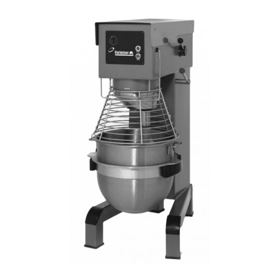
- Page 1 FOOD MIXER SPARE PART AND OPERATION MANUAL Model W80, W100N, W150PL 1993 to Present Form 109 (08/10)
- Page 2 -READ BEFORE OPERATING- Caution Varimixer recommends that mixer operators be at least 18 years of age and be thoroughly trained on the use of the mixer. Varimixer recommends that the following precautions be adopted to help make the mixer operation safer and more efficient.
-
Page 3: Limited Warranty
LIMITATIONS OF LIABILITY In the event of warranty claim or otherwise, the sole obligation of Varimixer shall be the repair and/or replacement at the option of Varimixer, of the appliance or component or part thereof Such repair or replacement shall be the expense of Varimixer except that travel over 100 miles or two hours, overtime, and holiday charges shall be,, the expense of the purchaser. -
Page 4: Table Of Contents
TABLE OF CONTENTS W80-W100PL Installation Instructions....................4 Operating Instructions.....................5 Cleaning-Maintenance....................6 Belt Adjustments and Removal..................7 Adjusting the Bowl Height....................8 Capacity Chart........................9 Machine Column......................11-14 Bowl Arms........................15-18 Planetary Head......................19-20 Transmission......................21-22 Speed Lever Assembly....................23-24 Attachment Drive....................25-26 Bowl Screen......................27-28 Instrument Panel....................29-32 Accessories......................33-34 Electrical Diagrams....................35-40 W150PL W150PL Manual......................42... -
Page 5: Installation Instructions
Read this page entirely BEFORE beginning installation. VARIMIXER INSTALLATION INSTRUCTIONS UNDER NO CIRCUMSTANCES ARE THE SPEED LEVER, BOWL LIFT LEVER, OR THE BOWL ARMS TO BE USED TO MOVE THE MIXER INTO PLACE. DAMAGE WILL RESULT TO THE UNIT. IT IS RECOMMENDED THAT THE TOP LID BE REMOVED BEFORE MOVING THE UNIT. - Page 6 OPERATION OF THE MIXER: Open the bowl screen and place the bowl in the bowl arms. Note: The bowl arms must be in lowest position and the bowl must be pushed all the way into the bowl arms. (Fig.3). Place the mixing tool in the bayonet shaft. The pin on the tool must be turned into the bayonet hole (fig.2).
-
Page 7: Operating Instructions
Correct use of tools: Maintenance and Lubrication: The variable speed pulleys must be lubricated regularly, i.e. a lubrication interval of approx. 60 hours of operation or once a Whips should never be struck week. against hard objects, this will decrease the life of the tool. Lubrication of variable speed pulleys: -Start the mixer and increase the speed to approx. -
Page 8: Cleaning-Maintenance
In such cases the distance (X) must be reduced. (+ or - 1/8" of 12 1/4") 6. Then follow the section: “Adjustment of speed” (X) W80 = 12 1/4" +/- 1/8" (X) W100 = 12 1/4" +/- 1/8"\ (X) W150 = 12 1/4" +/- 1/8". -
Page 9: Belt Adjustments And Removal
The bowl arms must be raised to normal working position. The adjusting diameter (Y) shall be measured inside between the bowl arms (fig.6a): Adjusting diameter (Y): W80 = 20 3/8" W100 = 21 13/16" In case the bowl fastening is too loose, remove the lock ring (B) and draw the bearing (A) from the shaft (C). -
Page 10: Adjusting The Bowl Height
Product W100 W150 Dough, Bread-65%AR 105 Lbs. 155 Lbs. 190 Lbs. Dough, Pizza-50% AR 90 Lbs. 135 Lbs. 175 Lbs. Dough, Donut-Yeast 80 Lbs. 150 Lbs. 170 Lbs. Dough, Donut-Cake 60 Lbs. 140 Lbs. 225 Lbs. Pie Dough 69 Lbs. 95 Lbs. -
Page 11: Capacity Chart
Notes:... -
Page 13: Machine Column
Machine Column W80-W100 Fig. Description W100 Top Lid 100-21 100-21 Screw for Lid M6x20 STA 5017 STA 5017 Threaded Bushing STA 6580 STA 6580 Ground Screw STA 5232 STA 5232 Arrow Label 15-214 15-214 Plug Button STA 6519 STA 6519... - Page 15 Bowl Lift Microswitches W80-W100 Fig. W100 Description Microswitch Bracket (Manual Lift) 81-612 Microswitch 81-173 Screw STA 5270 Microswitch Bracket Assembly 81-174 81-174 (Power Bowl Lift)
-
Page 17: Bowl Arms
Manual Bowl Lift (W80 Only) Fig. Description 15-65 Lift Nut 60-63 Crank Arm 81-68 Bowl Arm Shaft 81-83 Lifting Rod 60-110 Lift Spring STA 2020 STA 3408 Snap Ring STA 3462 Snap Ring STA 5088 Screw STA 5827 STA 6205... - Page 19 Power Bowl Lift W80-W100 Fig. W100 Description Upper Bowl Lift Motor Bracket 81-86.40 81-86.40 Bowl Arm Shaft 81-68 101-68 Lift Spring 60-110 60-110 Snap Ring STA 3408 STA 3408 Snap Ring STA 3462 STA 3462 Screw STA 5088 STA 5088...
-
Page 21: Planetary Head W80-W100
Planetary Head W80-W100 Fig. W100 Description V-Belt (Must be changed as a set) 100-90.1 100N-90.2 Order qty 3 Order qty 4 Snap Ring STA 3419 STA 3419 Washer STA 6048 STA 6048 Snap Ring STA 3419 STA 3419 Planetary Pulley... -
Page 23: Transmission W80-W100
Transmission W80-W100 Fig. W100 Description Grease Zerk STA 3220 STA 3220 Washer STA 6018 STA 6018 Clamping Ring w/screw 27-227 27-227 Screw f/clamping ring STA 5612 STA 5612 Vari Speed Collar 15-17 15-17 Ball Bearing 15-103 15-103 Movable Pulley 60-15.1M 60-15.1M... -
Page 25: Speed Lever Assembly
Speed Lever System W80-W100 Fig. W80-W100 Description 80N-47M Speed Lever W80 100N-47M Speed Lever W100 30N-47.10 Disc w/ arrow 30N-47.20 White Clamp STA 3306 Black Knob STA 3414 Snap Ring STA 5247 Screw... -
Page 27: Attachment Drive
Attachment Drive (W80 Only) Fig. Description STA 3220 Grease Zerk 60-61 Motor Mount Plate STA 5018 Slotted Screw STA 6054 Washer 15-11 Gear Case Cover 20-104 Ball Bearing STA 3410 Snap Ring STA 2007 Key f/motor pulley 20-52 Upper attachment drive shaft... -
Page 29: Bowl Screen
Bowl Screen W80-W100 Fig. W80-W100 Description 225/80N Bowl Screen Kit W80 225/100N Bowl Screen Kit W100 STA 5250 Screw STA 5819 56SN30-22 Bowl Screen Cam notched STA 5665 Set Screw f/cam STA 5665 Set Screw f/keeper 56SN30-21 Bushing 56SN30-24 Nut f/ bushing... -
Page 31: Instrument Panel
Electrical Control Panel W80-W100 1998-Present Fig. W80-W100 Description 60-86.1 Power Bowl Lift Switch (if applicable) 31-174.2 Start Button complete 31-174.3 Stop Button complete 30-188.15 Timer (220v) 30-190 Timer Scale 15 minute STA 5987 STA 6483 Cable Inlet f/14/2 cable STA 3017... - Page 33 Electrical Power Supply W80-W100 1998-Present Fig. W80-W100 Description 20E-418 Fuse 20E-416 Fuse Holder 100-88.5 Contactor 220V 20-88.91 Contactor 480V 20-88.47 Auxiliary Switch 20-88.24 Thermal Overload 11-16 Amps 20-88.21 Thermal Overload 4-6.2 Amps 140E-420 Relay 24VDC IDEC RH1B-U 140E-421 Relay Socket 100N-86.01...
-
Page 35: Accessories
Accessories W80-W100 Fig. W100 Description Standard Stainless Steel Bowl 203/100N 203/80N Stainless Steel Bowl (downsized 60) 203/60N Stainless Steel Bowl (downsized 40) 203/40N 203/40BN Standard Dough Hook 213/100D 213/80D Dough Hook (downsized) 213/40N 213/40BN Standard Flat Beater 205/100N 205/80N Flat Beater (downsized 60 QT) - Page 36 W80-W100 Wiring Diagram with Power Bowl Lift 1988-1996...
-
Page 37: Electrical Diagrams
W80-W100 Wiring Diagram with Power Bowl Lift 1988-1996... - Page 38 W80-W100 Wiring Diagram with Power Bowl Lift 1996...
- Page 39 This page intentionally left blank.
- Page 40 W80-W100 Front Panel Wiring Diagram with Power Bowl Lift 2005-Present...
- Page 41 W80-W100 Power Supply Wiring Diagram with Power Bowl Lift 2005-Present...
- Page 42 5489 Campus Drive Shreveport LA 71129 (800) 222-1138 (318) 635-3131 Fax www.varimixer.com...
Need help?
Do you have a question about the W80 and is the answer not in the manual?
Questions and answers