Table of Contents
Advertisement
Quick Links
Download this manual
See also:
User Manual
SERVICE MANUAL
Ver 1.1 2001.04
Signalling format
Frequency range
GSM power class
DCS power class
SIM chip
Display
Channel spacing
Number of channels
Frequency stability
RF output power
Battery life
Power requirements
Operating temperature
Accessories operating temperature
Battery pack charging temperature
Dimensions
Weight
Volume
<Supplied accessories>
• AC Adaptor
• Battery (std.)
• Desk Top Charger
• Hand Strap
• AC Cable
Design and specifications are subject to change
without notice.
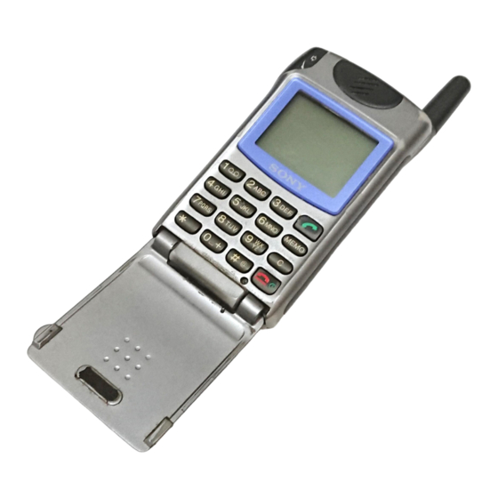
CMD-Z5 / Z18
SPECIFICATIONS
Dual-Band
E-GSM 900 MHz,Transmit: 880 – 915 MHz
Receive: 925 – 960 MHz
DCS 1800 MHz, Transmit: 1710 – 1785 MHz
Receive: 1805 – 1880 MHz
Class 4 (2W)
Class 1 (1W)
Pluggable mini SIM card
High resolution grey scale full graphics display
Resolution: 96 × 72 pixels
Graphic Icons
5 lines × 12 (normal font numeric) characters
200 kHz
E-GSM:
174
DCS:
374
Transmit frequency drift (synchronized)
< ± 0.1 p.p.m
GSM: 2W
DCS: 1W
Standby: 30h – 130h standard battery
50h – 220h extended battery
Talk time:1h30 – 3h40
2h30 – 6h extended battery
4.0 V (nominal)
-10°C to +55°C
±0°C to +45°C
±0°C to +40°C
88 mm × 49 mm × 21.5 mm
82.5 g
3
78 cm
QN-2TC
QN-Z5BPS
QN-Z5DTC
E Model
standard battery
Advertisement
Table of Contents


Need help?
Do you have a question about the CMD-Z5 and is the answer not in the manual?
Questions and answers