Sign In
Upload
Download
Table of Contents
Contents
Add to my manuals
Delete from my manuals
Share
URL of this page:
HTML Link:
Bookmark this page
Add
Manual will be automatically added to "My Manuals"
Print this page
×
Bookmark added
×
Added to my manuals
Manuals
Brands
LG Manuals
Vacuum Cleaner
V-CA241NE SERIES
Service manual
LG V-CA241NE SERIES Service Manual
Hide thumbs
Also See for V-CA241NE SERIES
:
Owner's manual
(17 pages)
1
Table Of Contents
2
3
4
5
6
7
8
9
10
11
12
13
14
15
16
17
18
19
20
page
of
20
Go
/
20
Contents
Table of Contents
Troubleshooting
Bookmarks
Table of Contents
Vacuum Cleaner
Table of Contents
Safety Precautions
Cautions
Description
Specifications
Disassembly
Disassembly
Trouble Shooting Guide
Schematic Diagram
Circuit Diagram
Exploded View
Replacement Parts List
Appendix
1 The Type of Power Cord & Parts Number
2 Color & Parts Number
3 Motor & Pwb Assy Parts Number
Advertisement
Quick Links
1
Vacuum Cleaner
2
Table of Contents
3
Specifications
4
Description
5
Disassembly
6
Schematic Diagram
7
Exploded View
8
Replacement Parts List
Download this manual
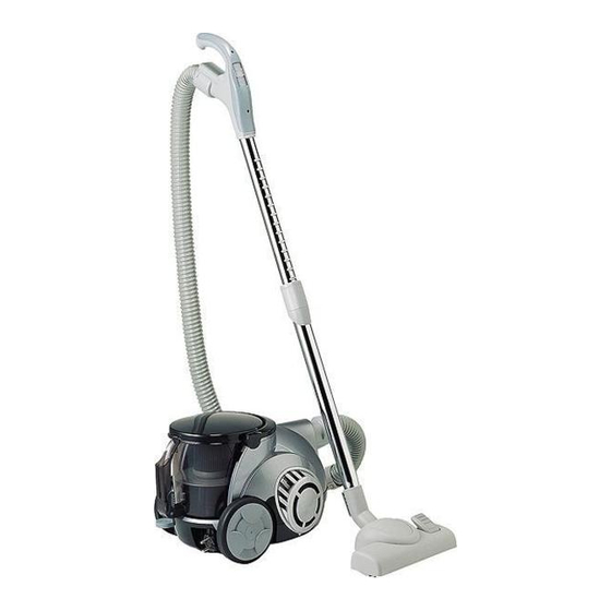
VACUUM CLEANER
SERVICE MANUAL
CAUTION
BEFORE SERVICING THE UNIT, READ THE "SAFETY PRECAUTIONS"
IN THIS MANUAL.
MODEL : V-CA241NE** / V-CA241HE**
V-CA241NT** / V-CA241HT**
V-C7141NTR / V-C7142NT / V-C7143HTR / V-C7145HT
V-C7150HTV / V-C7153HTV / V-C7155HEU
Table of
Contents
Previous
Page
Next
Page
1
2
3
4
5
Advertisement
Table of Contents
Need help?
Do you have a question about the V-CA241NE SERIES and is the answer not in the manual?
Ask a question
Questions and answers
Related Manuals for LG V-CA241NE SERIES
Vacuum Cleaner LG V-CA251NE Series Owner's Manual
(17 pages)
Vacuum Cleaner LG V-CA241HT series Owner's Manual
(36 pages)
Vacuum Cleaner LG V-CA241NT Series Owner's Manual
(17 pages)
Vacuum Cleaner LG V-C7141NTR Owner's Manual
(16 pages)
Vacuum Cleaner LG V-CA484STQ Service Manual
(17 pages)
Vacuum Cleaner LG V-CA251NTS Service Manual
(15 pages)
Vacuum Cleaner LG V-CA251NT series Owner's Manual
(16 pages)
Vacuum Cleaner LG V-CA701HTQ Service Manual
(23 pages)
Vacuum Cleaner LG V-CA241N Series Owner's Manual
(19 pages)
Vacuum Cleaner LG V-CA241H Series Owner's Manual
(19 pages)
Vacuum Cleaner LG VCARPETX Owner's Manual
Cleaning robot (48 pages)
Vacuum Cleaner LG VCA404 Series Owner's Manual
(24 pages)
Vacuum Cleaner LG V-C7153HTV Service Manual
(20 pages)
Vacuum Cleaner LG VC6818NR Owner's Manual
New type cyclone vacuum cleaner (19 pages)
Vacuum Cleaner LG VC5020 Series Owner's Manual
(28 pages)
Vacuum Cleaner LG VC9204FS User Manual
(28 pages)
This manual is also suitable for:
V-ca241nt series
V-ca241ht series
V-c7141ntr
V-ca241he series
V-c7142nt
V-c7143htr
...
Show all
V-c7145ht
V-c7150htv
V-c7153htv
V-c7155heu
Table of Contents
Print
Rename the bookmark
Delete bookmark?
Delete from my manuals?
Login
Sign In
OR
Sign in with Facebook
Sign in with Google
Upload manual
Upload from disk
Upload from URL


Need help?
Do you have a question about the V-CA241NE SERIES and is the answer not in the manual?
Questions and answers