
Related Manuals for Guardian QUIETPACT 85D


Summary of Contents for Guardian QUIETPACT 85D
-
Page 1: Installation Instructions
Owner’s Manual and Installation Instructions Liquid-cooled Recreational Vehicle Generator • Model: 005432-0 QUIETPACT™ 85D This manual should remain with the unit. -
Page 2: Introduction
INTRODUCTION The operator (i.e., the driver) is responsible for the proper and safe use of the vehicle and its equipment, Thank you for purchasing this model by Generac and for the safety of all vehicle occupants. Before Power Systems, Inc. This model is designed and man- using this equipment, we strongly recommend that ufactured to supply electrical power for recreational the operator read this manual and thoroughly under-... -
Page 3: Table Of Contents
Table of Contents Recreational Vehicle Generator Part I – Owner’s Manual Part II – Installation Instructions Introduction ........Inside Front Cover Safety Rules ..............18 Read This Manual Thoroughly ........IFC Section 1 – General Information ....... 20 Contents ..............IFC Operation and Maintenance ........IFC Purpose and Scope of the Manual ..... -
Page 4: Safety Rules
Safety Rules Recreational Vehicle Generator SAVE THESE INSTRUCTIONS – The manufacturer suggests that these rules for safe operation be copied and posted in potential hazard areas of the recreational vehicle. Safety should be stressed to all operators and potential operators of this equipment. •... - Page 5 Safety Rules Recreational Vehicle Generator • When working on this equipment, remain alert • Never wear jewelry when working on this equip- at all times. Never work on the equipment when ment. Jewelry can conduct electricity, resulting in physically or mentally fatigued. electric shock, or may get caught in moving com- ponents, causing, injury.
-
Page 6: Section 1 - General Information
Section 1 – General Information Recreational Vehicle Generator GENERATOR IDENTIFICATION Please record the following information from the generator DATA LABEL or information label, located below the user control panel. 1. Model Number _____________________ 2. Serial Number __________________ 3. kW Rating _________________________ 4. -
Page 7: Generator Applicability
Section 1 – General Information Recreational Vehicle Generator GENERATOR APPLICABILITY GENERATOR AC CONNECTION These generators have been designed and manufac- SYSTEM tured for supplying electrical power to recreational This generator is equipped with dual-stator AC power vehicles. DO NOT modify the generator nor use it for windings. - Page 8 Section 1 – General Information Recreational Vehicle Generator NOTE: Ethylene glycol base antifreeze is poisonous. Some installations using a “shared” fuel tank may Do not use mouth to siphon coolant from the have a generator fuel pickup tube that is shorter radiator, recovery bottle, or any container.
-
Page 9: Section 2 - Operation
Section 2 – Operation Recreational Vehicle Generator 1.5.6 GENERATOR 2.1.1 HOURMETER Rated Maximum Continuous AC Output at ... This indicates the length of time the engine/generator 85º F (29º C) Ambient ......8,500 Watts (8.5 kW) has operated, in hours and tenths of hours. Use the 100º... -
Page 10: Optional Remote Start/Stop
Section 2 – Operation Recreational Vehicle Generator OPTIONAL REMOTE START/STOP NOTE: This generator is equipped with a plug-in connec- Depending on the installation, the generator may tor that can be interfaced with an optional remote have either a separate fuel tank or “share” the panel provided inside the vehicle. -
Page 11: Starting The Generator
Section 2 – Operation Recreational Vehicle Generator STOPPING THE GENERATOR DANGER 1. Turn OFF all electrical loads, using the means provided in the vehicle (such as, a main-line cir- Never sleep in the vehicle while the genset is cuit breaker or transfer switch). running unless the vehicle has a working carbon 2. -
Page 12: Protection Systems
Section 2 – Operation Recreational Vehicle Generator 2.7.3 OVERSPEED SHUTDOWN • Induction-type motors (such as, those that run the vehicle’s furnace fan, refrigerator, air conditioner, A DC control circuit board senses engine speed from etc.) need about 2-1/2 time more watts of power the frequency of the alternator AC output. -
Page 13: Section 3 - Maintenance
Section 3 – Maintenance Recreational Vehicle Generator 2.8.2 OPERATION IN HIGH GRASS Figure 3.1 – Oil Maintenance Features OR BRUSH OIL FILL OIL DIPSTICK Never operate the generator while the vehicle is OPENING AND PLUG parked over high grass, weeds, brush, leaves, or REMOVABLE FRONT other combustible substance. -
Page 14: Servicing The Engine Air Filter
Section 3 – Maintenance Recreational Vehicle Generator SPARK ARRESTOR MUFFLER 8. Screw the new filter on by hand, until its gasket lightly contacts the oil filter adapter. Then, tighten The exhaust muffler supplied with the generator the filter an additional 3/4 to one turn. is a spark arrestor type. -
Page 15: Cleaning The Generator
Section 3 – Maintenance Recreational Vehicle Generator BATTERY MAINTENANCE All lead-acid batteries will discharge when not in use. The generator battery should be inspected per the Failure to provide and maintain a spark arres- “Service Schedule”. The following procedure should tor may be in violation of the law. -
Page 16: Cooling System
Section 3 – Maintenance Recreational Vehicle Generator DANGER Do not open or mutilate the battery. Released Do not remove the radiator pressure cap while electrolyte has been known to be harmful to the the engine is hot; otherwise, serious burns from skin and eyes, and to be toxic. -
Page 17: 3.12 Out-Of-Service Procedure
Section 3 – Maintenance Recreational Vehicle Generator 3.12 OUT-OF-SERVICE PROCEDURE 3.12.1 REMOVAL FROM SERVICE Prepare the generator for storage as follows: 1. Start the engine and let it run until it is thoroughly warmed up (at least five minutes), then shut off the engine. -
Page 18: 3.13 Service Schedule
Section 3 – Maintenance Recreational Vehicle Generator 3.13 SERVICE SCHEDULE ATTENTION: It is recommended that all service work be performed by the nearest Authorized Service Dealer. SYSTEM/COMPONENT PROCEDURE FREQUENCY X = Action Inspect Change Clean D = Daily W = Weekly R = Replace/Adjust as Needed M = Monthly Y = Yearly... -
Page 19: Part Ii - Installation Instructions
PART II – INSTALLATION INSTRUCTIONS DANGER ONLY QUALIFIED ELECTRICIANS OR CONTRACTORS SHOULD ATTEMPT INSTALLATION! -
Page 20: Safety Rules
Safety Rules Recreational Vehicle Generator DANGER: For fire safety, installation of a generator into a recreational vehicle must comply strictly with NFPA 70 (latest edition), “National Electrical Code”, Article 551, and NFPA 1192 (latest edition), “Standard for Recreational Vehicles”. In addition, installation must comply with the manufacturer’s instructions and recommendations. - Page 21 Safety Rules Recreational Vehicle Generator ELECTRICAL HAZARDS FIRE HAZARDS • For fire safety, the generator must be installed • The generator covered by this manual produces and maintained properly. Installation always dangerous electrical voltages that can cause fatal must comply with applicable codes, standards, electrical shock.
-
Page 22: Section 1 - General Information
Section 1 – General Information Recreational Vehicle Generator PURPOSE AND SCOPE 5. CSA Electrical Bulletin 946, available from the Canadian Standards Association, Housing and OF THE MANUAL Constructions Materials Section, 178 Rexdale Boulevard, Rexdale, Ontario, Canada, M9W 1R3. These Installation Instructions have been prepared especially for the purpose of familiarizing installers EQUIPMENT DESCRIPTION and owners of the applicable equipment with the... -
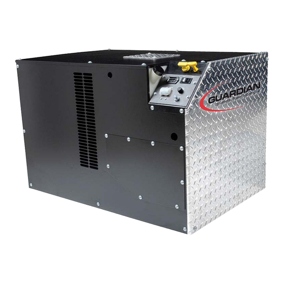
Page 23: Major Features And Dimensions
Section 1 – General Information Recreational Vehicle Generator Major Features and Dimensions — Drawing No. 0G6806-A Figure 1.2 – Major Features and Dimensions (Drawing 0G6806-A) -
Page 24: Section 2 - Installation
Section 2 – Installation Recreational Vehicle Generator LOCATION AND SUPPORT • Whether the generator is mounted above the hori- zontal support tubing or suspended below the tub- Be sure the installation complies with all standards ing, the supporting frame used must be structur- and codes listed in the "Standards Booklets"... -
Page 25: Generator Compartments
Section 2 – Installation Recreational Vehicle Generator 2.1.4 GENERATOR RESTRAINT Figure 2.3 – Typical Compartment Construction Use four 3/8"-16 hardened steel bolts (Grade 5) to fasten the generator to the supporting frame or the support tubing. These bolts must pass through (a) the generator mounting base, (b) the compartment floor (if a compartment is used), and (c) the support- ing framework (Figure 2.2). - Page 26 Section 2 – Installation Recreational Vehicle Generator • Seams and joints of the galvanized steel (whether DANGER used as a liner or for the compartment itself) must be lapped and mechanically secured. Such seams Do not install sound insulation or any absorbent may be manufactured, welded, bolted, riveted, or material on the compartment floor interior.
- Page 27 Section 2 – Installation Recreational Vehicle Generator 2.2.4 COMPARTMENT FLOOR CUTOUTS Figure 2.5 – Typical Noise Abatement Provide openings in the generator compartment for the following items (Figure 2.6): • Engine exhaust and cooling air outlets • Generator cooling air inlet and front service door •...
-
Page 28: Cooling And Ventilating Air
Section 2 – Installation Recreational Vehicle Generator COOLING AND VENTILATING AIR 2.3.2 COOLING AIR INLET OPENINGS It is absolutely essential that an adequate flow of The minimum size of the air inlet opening, whether air for cooling, ventilation, and engine combustion the generator is housed in a conventional compart- be supplied to the generator set. -
Page 29: Diesel Fuel System
Section 2 – Installation Recreational Vehicle Generator 2.3.4 TESTING THE INSTALLATION Figure 2.10 – Air Inlet Using Duct work The manufacturer recommends testing the installa- tion to be sure adequate cooling airflow is available to the unit, before placing the unit into service. If the unit shows signs of overheating, enlarge the air open- ings. - Page 30 Section 2 – Installation Recreational Vehicle Generator 2.4.2 GENERATOR FUEL SUPPLY LINES Because diesel fuels are less volatile than gasoline or gaseous fuels, they are considered safer from the standpoint of storage and handling. As a result, 2.4.2.1 Rigid Fuel Lines installers may tend to be careless in their installation Those lines used to supply fuel from a tank to the practices, which can result in poor engine perfor-...
-
Page 31: Exhaust System
Section 2 – Installation Recreational Vehicle Generator EXHAUST SYSTEM 2.5.2 EXHAUST SYSTEM SAFETY The generator exhaust system must be safely and • Maintain a clearance of at least 3 inches (76 mm) properly installed. Only approved exhaust system between exhaust system parts and any combus- parts must be used. -
Page 32: Electrical Connections
Section 2 – Installation Recreational Vehicle Generator • Use exhaust system parts recommended by the • If neutral conductors are used, they must be the manufacturer. Using unapproved exhaust mufflers same size as other leg wires. and exhaust system parts is the responsibility of •... - Page 33 Section 2 – Installation Recreational Vehicle Generator Figure 2.14 – Generator AC Output Leads 4. Renumber ground wire "44", located between the four-position terminal block and ground in Figure 2.15, as ground wire "33", as shown in T1 (Red) T2 Neutral (White) Figure 2.16.
- Page 34 Section 2 – Installation Recreational Vehicle Generator 2.6.4 CONDUIT 2.6.5 POWER SUPPLY CORD Route the connections between the generator and the The power supply cord must comply with all appli- junction box through approved, flexible conduit. The cable codes, standards, and regulations. It must be following general rules apply: large enough to handle the full amperage to which it will be subjected.
-
Page 35: Battery Installation
Section 2 – Installation Recreational Vehicle Generator Figure 2.18 – Installation With Isolation Receptacle 2.7.2 BATTERY CABLES DANGER Using battery cables that are too long or too small in If the vehicle’s electrical circuits can be powered diameter may cause a drop in voltage, which causes by any other source of electricity (such as, a starting problems. -
Page 36: Optional Accessories
Section 2 – Installation Recreational Vehicle Generator 2. Connect the battery cable from the battery post, • Use tools with insulated handles; indicated by a NEGATIVE, NEG, or (-), to the • Wear rubber gloves and boots; vehicle frame ground connection (Figure 2.19). •... -
Page 37: Section 3 - Post-Installation Startup Checks
Section 3 – Post-installation Start-up Checks Recreational Vehicle Generator CHECKS 2.8.1 REMOTE START/STOP CONNECTIONS 2. Refer to Part I, the “Starting the Generator” sec- tion, for cranking and starting instructions. The The following steps are necessary to connect the engine may require more cranking for initial remote start/stop option: starting, since the fuel lines have to be primed (use of the preheat switch will operate the genera-... -
Page 38: Installation Checklist
Section 3 – Post-installation Start-up Checks Recreational Vehicle Generator CHECKS INSTALLATION CHECKLIST EXHAUST SYSTEM ❑ Exhaust system complies with all applicable LOCATION AND SUPPORT codes. ❑ Generator is properly located. ❑ Exhaust system is properly and safely installed. ❑ Generator is properly supported. ELECTRICAL CONNECTIONS ❑... -
Page 39: Section 4 - Troubleshooting
Section 4 – Troubleshooting Recreational Vehicle Generator TROUBLESHOOTING GUIDE Problem Cause Correction The engine will not crank. 1. System control fuse blown 1. Replace fuse. 2. Loose corroded or defective 2. Tighten, clean, or replace, battery cables as necessary. 3. Defective engine Start/Stop 3. -
Page 40: Section 5 - Electrical Data
Section 5 — Electrical Data Recreational Vehicle Generator Electrical Schematic – 120/240 VAC Output– Drawing No. 0G7332-C... - Page 41 Section 5 — Electrical Data Recreational Vehicle Generator Electrical Schematic – 120/240 VAC Output – Drawing No. 0G7332-C...
- Page 42 Section 5 — Electrical Data Recreational Vehicle Generator Wiring Diagram 120/240 Dual Voltage– Drawing No. - 0G7333-D (Page 1 of 4)
- Page 43 Section 5 — Electrical Data Recreational Vehicle Generator Wiring Diagram 120 VAC– Drawing No. - 0G7333-D (Page 2 of 4)
- Page 44 Section 5 — Electrical Data Recreational Vehicle Generator Wiring Diagram 120/240 Dual Voltage– Drawing No. - 0G7333-D (Page 3 of 4)
- Page 45 Section 5 — Electrical Data Recreational Vehicle Generator Wiring Diagram 120 VAC– Drawing No. - 0G7333-D (Page 4 of 4)
-
Page 46: Section 6 - Exploded Views And Parts Lists
Section 6 — Exploded Views and Parts Lists Recreational Vehicle Generator Engine, Alternator Drive and Starter Assembly – Drawing No. 0G7350-B... - Page 47 Section 6 — Exploded Views and Parts Lists Recreational Vehicle Generator Engine, Alternator Drive and Starter Assembly – Drawing No. 0G7350-B ITEM PART NO. QTY. DESCRIPTION 0C5598 BEARING CARRIER FRONT 0C9674 BEARING CARRIER UPPER 0C6055H ROTOR ASSEMBLY 0C6054H STATOR ASSEMBLY 031971 BEARING #6205 2NSE C3 E SRI2 S 073159...
- Page 48 Section 6 — Exploded Views and Parts Lists Recreational Vehicle Generator Enclosure – Drawing No. 0G7351-B...
- Page 49 Section 6 — Exploded Views and Parts Lists Recreational Vehicle Generator Enclosure – Drawing No. 0G7351-B ITEM PART NO. QTY. DESCRIPTION 0G60920ST03 ENCLOSURE PANEL RH,WELDMENT 0G72980ST03 ENCLOSURE PANEL, TOP 0G60790ST03 ENCLOSURE PANEL LH 0G60810ST03 ENCLOSURE PANEL,FRONT 0G60610ST03 ENCLOSURE PANEL REAR,WELDMENT 0G7389 INSULATION, FRONT PANEL 0G7390...
- Page 50 Section 6 — Exploded Views and Parts Lists Recreational Vehicle Generator Cooling System – Drawing No. 0G7352-A...
- Page 51 Section 6 — Exploded Views and Parts Lists Recreational Vehicle Generator Cooling System – Drawing No. 0G7352-A ITEM PART NO. QTY. DESCRIPTION 0G64760ST03 COVER PLATE,SCRL WLDMNT 0G64470ST03 HOUSING, FAN SCROLL WLDMNT 0C4552 FAN, SQUIRREL CAGE 0C4554 SHAFT, FAN 0C4555 BEARING CARRIER 0C4557 KEY SQ 3/16 X 5/8 STEEL 0C4556A...
- Page 52 Section 6 — Exploded Views and Parts Lists Recreational Vehicle Generator Fuel and Electrical Systems – Drawing No. 0G7355-A...
- Page 53 Section 6 — Exploded Views and Parts Lists Recreational Vehicle Generator Fuel and Electrical Systems – Drawing No. 0G7355-A ITEM PART NO. QTY. DESCRIPTION 0C6946A FUEL PUMP ASSY REWRK 052219 BARBED STR 1/8NPT X 5/16 069598B BULKHEAD FITTING 1/8 NPT 022097 WASHER LOCK M6-1/4 038750...
- Page 54 Section 6 — Exploded Views and Parts Lists Recreational Vehicle Generator Customer Controls Assembly – Drawing No. 0G7356-B...
- Page 55 Section 6 — Exploded Views and Parts Lists Recreational Vehicle Generator Customer Controls Assembly – Drawing No. 0G7356-B ITEM PART NO. QTY. DESCRIPTION 080825 SWITCH RKR DPST 0C45400ST03 COVER ENG CONTRL BOX 0C1457 HOURMETER 032300 HOLDER FUSE 055920 SWITCH SPST SPADE PNL MNT 043181 SCREW PHM M3-0.5 X 10MM 022159...
- Page 56 Section 6 — Exploded Views and Parts Lists Recreational Vehicle Generator Base Frame – Drawing No. 0D2357-C TORQUE SPECIFICATIONS CHART ITEM # TORQUE 18 FT-LBS STARTER GRD. CABLE ITEM PART NO. QTY. DESCRIPTION ITEM PART NO. QTY. DESCRIPTION 0D2126 Base Frame Weldment 022097 Washer, Split Lk –1/4-M6 0D2131...
- Page 57 Section 6 — Exploded Views and Parts Lists Recreational Vehicle Generator Electrical Enclosure Assembly – Drawing No. 0G7353-A ITEM PART NO. QTY. DESCRIPTION ITEM PART NO. QTY. DESCRIPTION 0G71570ST03 WELDMENT, CONTROLLER BOX 0G7440 HARNESS, AC OUTPUT 071914 BLOCK MARATHON 4 POS 600V 0G7846 HARN ENG CONTROL PANEL 1.1L RV 0830490SRV...
- Page 58 Section 6 — Exploded Views and Parts Lists Recreational Vehicle Generator Intake and Exhaust System – Drawing No. 0G7354-A ITEM PART NO. QTY. DESCRIPTION ITEM PART NO. QTY. DESCRIPTION 075674 GASKET EXHAUST ADAPTOR 022129 WASHER LOCK M8-5/16 0F28730173 045771 NUT HEX M8-1.25 G8 CLEAR ZINC 0E9581A AIR CLEANER, 152.4MM 058443...
- Page 59 Section 6 — Exploded Views and Parts Lists Recreational Vehicle Generator 1.0 Liter Diesel Camshaft – Drawing No. 0F6230 ITEM PART NO. QTY. DESCRIPTION 0F28730164 CAMSHAFT ASSEMBLY 0709390233 CAMSHAFT GEAR 0709390195 0709390234 GEAR 0709390235 SPACER 0709390236 BALL BEARING 0709390237 SLIDER 0709390238 PLATE 0709390241...
- Page 60 Section 6 — Exploded Views and Parts Lists Recreational Vehicle Generator 1.0 Liter Diesel Oil Pump – Drawing No. 0F6231 ITEM PART NO. QTY. DESCRIPTION 0709390250 IDLER GEAR ASSEMBLY 0709390251 THRUST WASHER 0709390252 SPRING 0709390253 ROTOR 0709390254 OIL PUMP COVER 0709390255 0.10MM SHIM 0709390532...
- Page 61 Section 6 — Exploded Views and Parts Lists Recreational Vehicle Generator 1.0 Liter Diesel Cylinder Head – Drawing No. 0G7500-A ITEM PART NO. QTY. DESCRIPTION ITEM PART NO. QTY. DESCRIPTION 0G23210107 CYLINDER HEAD ASSEMBLY 0G23210108 0F28730119 SEALING CAP 0G23210109 HEAD GASKET, 1.2mm THICK 0F28730120 SEALING CAP 0G23210110...
- Page 62 Section 6 — Exploded Views and Parts Lists Recreational Vehicle Generator 1.0 Liter Diesel Engine Block – Drawing No. 0G7501-A ITEM PART NO. QTY. DESCRIPTION ITEM PART NO. QTY. DESCRIPTION 0G23210152 OIL PAN 0F28730143 HEAD COVER 0709390140 BOLT 0F28730144 OIL STOPPER 0G23210153 BOLT 0709390186...
- Page 63 Section 6 — Exploded Views and Parts Lists Recreational Vehicle Generator 1.0 Liter Diesel Water Pump – Drawing No. 0G7502-A ITEM PART NO. QTY. DESCRIPTION ITEM PART NO. QTY. DESCRIPTION 0F28730169 WATER PUMP ASSEMBLY 0G23210154 THERMOSTAT CASE 0F28730170 GASKET 0F28730180 BOLT 0F28730171 BOLT...
- Page 64 Section 6 — Exploded Views and Parts Lists Recreational Vehicle Generator 1.0 Liter Diesel Cylinder Block– Drawing No. 0G7503-A ITEM PART NO. QTY. DESCRIPTION ITEM PART NO. QTY. DESCRIPTION 0G23210100 CYLINDER BLOCK 0709390116 DOWEL PIN 0709390104 BLANK PLUG 0709390117 DOWEL PIN 0F28730101 SEALING CAP 0709390118...
- Page 65 Section 6 — Exploded Views and Parts Lists Recreational Vehicle Generator 1.0 Liter Diesel Rocker Arm Assembly – Drawing No. 0G7504-A ITEM PART NO. QTY. DESCRIPTION ITEM PART NO. QTY. DESCRIPTION 0F28730128 ROCKER ARM ASSEMBLY 0G23210132 OIL PIPE 0F28730129 INTAKE ROCKER ARM 0F28730146 GASKET 0F28730130...
- Page 66 Section 6 — Exploded Views and Parts Lists Recreational Vehicle Generator 1.0 Liter Diesel Crankshaft, Piston and Flywheel – Drawing No. 0G7505-A ITEM PART NO. QTY. DESCRIPTION ITEM PART NO. QTY. DESCRIPTION 0G23210113 COMPLETE CRANKSHAFT 0709390198 BOLT 0709390194 CRANKSHAFT GEAR 0G23210124 BOLT 0709390195...
- Page 67 Section 6 — Exploded Views and Parts Lists Recreational Vehicle Generator 1.0 Liter Diesel Timing and Governor – Drawing No. 0G7506-A ITEM PART NO. QTY. DESCRIPTION ITEM PART NO. QTY. DESCRIPTION 0F28730186 HOUSING, TIMING GEAR 0709390304 0709390286 SPRING PIN 0709390305 SNAP RING 0F28730187 GASKET...
- Page 68 Section 6 — Exploded Views and Parts Lists Recreational Vehicle Generator 1.0 Liter Diesel Injector Pump – Drawing No. 0G7507-A ITEM PART NO. QTY. DESCRIPTION ITEM PART NO. QTY. DESCRIPTION 0G23210133 INJECTION PUMP ASSEMBLY 0F28730173 0F28730201 ADJUSTING SHIM SET 0F28730209 GLOW PLUG 0F28730173 0F28730210...
- Page 69 Section 6 — Exploded Views and Parts Lists Recreational Vehicle Generator 1.0 Liter Diesel Fuel Supply – Drawing No. 0G7508-A ITEM PART NO. QTY. DESCRIPTION ITEM PART NO. QTY. DESCRIPTION 0F28730215 FUEL FILTER SUPPORT ASSEMBLY 068736 275MM HOSE, 3/16” SAE 30R2 0G23210155 FUEL FILTER 068736...
-
Page 70: Section 7 - Warranty
Section 7 – Warranty Recreational Vehicle Generator FEDERAL AND CALIFORNIA EMISSIONS CONTROL WARRANTY STATEMENT (for non-road Diesel engines rated under 19 kW) YOUR WARRANTY RIGHTS AND OBLIGATIONS The U.S. Environmental Protection Agency (EPA), the California Air Resources Board (CARB), Generac Power Systems, Inc. - Page 71 Section 7 – Warranty Recreational Vehicle Generator OBLIGATIONS AND RIGHTS OF THE MANUFACTURER AND OWNER The new model year, class of diesel engine, and emission application determination for your engine are identified on the emission control information label affixed to the right-hand side of your engine's timing gear case. The warranty period begins on the date the new equipment is sold to the first retail purchaser.
- Page 72 Proof-of-purchase is required and must be presented to a Generac Authorized Warranty Service Facility prior to the performance of any warranty service. All warranty expense allowances are subject to the conditions defined in Guardian’s Warranty Policies and Procedures Guide. THIS WARRANTY SHALL NOT APPLY TO THE FOLLOWING: •...
Need help?
Do you have a question about the QUIETPACT 85D and is the answer not in the manual?
Questions and answers