Table of Contents
Advertisement
Quick Links
Advertisement
Chapters
Table of Contents

Related Manuals for Gefen EXT-CU-LAN


Summary of Contents for Gefen EXT-CU-LAN
- Page 1 *Preferred Matrix Controller EXT-CU-LAN User Manual Release A5...
- Page 2 Important Safety Instructions Read these instructions. Keep these instructions. Heed all warnings. Follow all instructions. Do not use this product near water. Clean only with a dry cloth. Do not block any ventilation openings. Install in accordance with the manufacturer’s instructions.
- Page 3 Gefen warrants the equipment it manufactures to be free from defects in material and workmanship. If equipment fails because of such defects and Gefen is notified within two (2) years from the date of shipment, Gefen will, at its option, repah or replace the equipment, provided that the equipment has not been subjected to mechanical, electrical, or other abuse or modifications.
- Page 4 Contacting Gefen Technical Support Technical Support (818) 772-9100 (800) 545-6900 8:00 AM to 5:00 PM Monday - Friday, Pacific Time (818) 772-9120 Email support@gefen.com http://www.gefen.com Mailing Address Gefen, LLC c/o Customer Service 20600 Nordhoff St. Chatsworth, CA 91311 Product Registration Register your product here: http://www.gefen.com/kvm/Registry/Registration.jsp...
- Page 5 • The “discovery” feature, used by the Matrix Controller, relies on a proprietary network broadcast protocol that is used for identification of Gefen KVM over IP products. Broadcast packets and access using ports 53334 and 53335 is required for this feature to work.
- Page 6 Matrix Controller is a trademark of Gefen, LLC. © 2015 Gefen, LLC. All Rights Reserved. All trademarks are the property of their respective owners. Gefen, LLC reserves the right to make changes in the hardware, packaging, and any accompanying documentation without prior written notice.
- Page 7 Licensing This product uses software that is subject to open source licenses, including one or more of the General Public License Version 2 and Version 2.1, Lesser General Public License Version 2.1 and Version 3, BSD, and BSD-style licenses. Distribution and use of this product is subject to the license terms and limitations of liability provided in those licenses.
- Page 8 Seamless integration with Gefen Syner-G™ software allows for quick installation and configuration on a network • Automatic assignment of IP addresses for all Gefen Video and KVM over IP devices on a network • Front panel control push-buttons/display, handheld IR remote, and web server interface allow easy and convenient end-user operation •...
-
Page 9: Table Of Contents
Table of Contents Getting Started Introduction......................2 Panel Layout ....................2 IR Remote Control ..................5 Installing the Batteries ................... 7 Setting the IR Channel .................. 8 Installation ......................9 Combined Mode .................... 9 Separate Mode .................... 13 Configuring Slave Units ................16 Device Configuration ................... - Page 10 Table of Contents Masking an Output ..................91 Selecting Presets ..................93 Setting the Network Mode ................97 Control IP Settings ..................100 Video IP Settings ..................107 Telnet / TCP Settings ................113 UDP Settings ..................... 118 Discovery Settings ..................124 Setting the IR Channel for the Matrix Controller ........
- Page 11 This page left intentionally blank.
- Page 12 This page left intentionally blank.
- Page 13 Matrix Controller Getting Started...
-
Page 14: Introduction
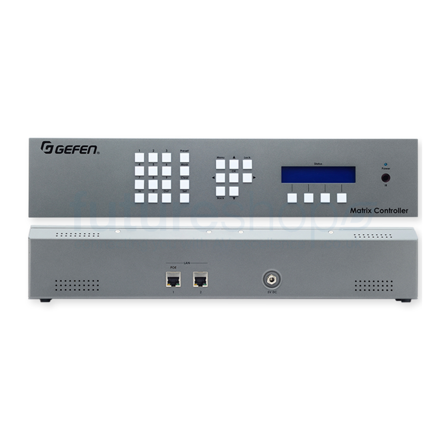
Introduction Page Title Panel Layout Preset ® Menu Lock Mask Status Power Clear Back Matrix Controller Preset Menu Lock Mask 5V DC Clear Back Preset ® Menu Lock Status Mask Power Clear Back Matrix Controller 5V DC page | 2... - Page 15 Introduction Page Title Name Description LCM display Provides feedback and status of the Matrix Controller during various operations. Soft buttons Each of these buttons will have a different function, depending upon the read-out in the LCM display. Power This LED indicator will glow solid blue when the Matrix Controller is powered.
- Page 16 Introduction Page Title Name Description Back Press this button to return to a previous screen in the LCM display. Lock Press this button to lock the Matrix Controller. When the Matrix Controller is locked, the enter passcode screen will be shown in the LCM display.
-
Page 17: Ir Remote Control
Introduction Page Title IR Remote Control Each of the buttons on the IR Remote Control are identical in functionality to those of the buttons on the front panel. page | 5... - Page 18 Introduction Name Description Preset Press this button to select a preset. Mask Press this button to mask an output. Masking an Output (page 91) more information. Clear Press this button to clear the current entry. Menu Press this button to access the menu system.
-
Page 19: Installing The Batteries
Introduction Installing the Batteries Remove the back cover the IR remote control unit. Insert two 1.5V AAA-type batteries, as shown, within the battery compartment. Power Mask Output Menu Preset Back Lock Input *Preferred ® RMT-88 Replace the back cover. Warning! Risk of explosion if battery is replaced by an incorrect type. -
Page 20: Setting The Ir Channel
Introduction Setting the IR Channel Information In order for the IR remote control to function properly, both the Matrix Controller and the IR remote control must be set to the same IR channel. In order for the included IR remote control to communicate with the Matrix Controller, the IR remote control must be set to the same channel as the matrix. -
Page 21: Installation
Combined Mode Connect a shielded CAT-5e (or better) cable from each of the Gefen KVM over IP units to a managed switch. Refer to the User Manual(s) for the Gefen KVM over IP units to obtain the network requirements. Router... - Page 22 Connect a shielded CAT-5e (or better) cable from the LAN 1 port on the Matrix Controller to the same network where the Gefen KVM over IP units are connected. Connect the included power supply to the 5V DC power receptacle on the rear panel of the Matrix Controller.
- Page 23 IP address 192.168.1.74 is not assigned to another device in order to avoid conflicts. Router Managed Switch Computer to Gefen KVM over IP LAN 1 Devices EXT-CU-LAN Matrix Controller Set the subnet mask to 255.255.255.0.
- Page 24 Installation 10. Type admin (case-sensitive) in both the Username and Password fields, then click the Login button. 11. To continue, skip to Device Configuration (page 20). page | 12...
-
Page 25: Separate Mode
Combined Mode (page Connect a shielded CAT-5e (or better) cable from each of the Gefen KVM over IP units to a managed switch. Refer to the User Manual(s) for the Gefen KVM over IP units to obtain the network requirements.. - Page 26 Preset ® Menu Lock Status Mask Power ext-cu-lan initializing... Clear Back Matrix Controller After the Matrix Controller has completed the initialization process, the following message will appear in the LCM display on the front panel. The default passcode used to access the front panel is 123456.
- Page 27 Installation Important Do not use the IP address 192.168.1.74 because this is the IP address of the Matrix Controller. If the current network configuration is already within this range, make sure that the IP address 192.168.1.74 is not assigned to another device in order to avoid conflicts.
-
Page 28: Configuring Slave Units
Preset ® Menu Lock Installation Status Mask Clear Configuring Slave Units Back More than one Matrix Controller can be connected to a network. When using multiple Matrix Controllers, one Matrix Controller must be configured as a master and the remaining Matrix Controllers are configured as slave. - Page 29 Installation The following message box will be displayed: Click the OK button. The login screen will be displayed. Enter the administrator username and password and then click the Login button. Return to the System > Basic Settings tab and click the Reboot button. page | 17...
- Page 30 Installation The following message box will be displayed. Click the OK button to reboot the Matrix Controller. Click the OK on the following message box when it is displayed: 10. The following message box will be displayed while the Matrix Controller is rebooting. The Matrix Controller is now set-up as a slave.
- Page 31 To the right of the IP address and MAC address, the Description and User fields are displayed. The Description field can be changed as desired. For example, we could change this field to “EXT-CU-LAN Slave” for easy identification by the Gefen Syner-G software.
-
Page 32: Device Configuration
Matrix Controller. Click the I/O tab. All Gefen KVM over IP products, that are connected to the network, will be displayed under the Input and Output lists, as shown below. The Matrix Controller automati- cally discovers all available Gefen KVM over IP products. - Page 33 Important Before proceeding, contact your IT administrator for a valid range of consecutive IP addresses that can be applied to the Gefen KVM over IP products (e.g. 192.168.1.100 to 192.168.1.150). Enter the provided IP addresses (from the IT administrator) in the IP Range From and To fields.
- Page 34 Click the Auto Assign button on the right side of the screen, under the Outputs list. The following message box will be displayed: During the Auto Assign procedure, the Gefen KVM over IP products may reboot multiple times. The Web interface will not be available during this process. DO NOT attempt to refresh the page during the process.
- Page 35 Device Configuration Click the OK button to continue. The following message box will be displayed and will disappear when the process has completed: Provide a unique description for each input and output device. Make sure the descriptions are meaningful (e.g. “Blu-ray”, “Samsung 65”, etc.). This step is highly recommended and will provide easy management of devices, particularly in large-scale setups.
- Page 36 Device Configuration Click the Edit Device button. Note that only one device can be changed at a time. If more than one device is selected, then the Edit Device button will be disabled. The Edit Device dialog box will be displayed. page | 24...
- Page 37 Device Configuration The default device name will be displayed in the Description field. Click in the Description field and change the name. Click the Save button on the Edit Device dialog. The processing message box will be displayed and after a few seconds, the device description will be updated.
- Page 38 This page left intentionally blank.
-
Page 39: 2 Basic Operation
Matrix Controller Basic Operation page | 27... -
Page 40: Groups, Users, And Members
Groups, Users, and Members In order to introduce a level of organization to how end-users interact with the Matrix Controller, it is important to first define the concepts of groups, users, and members. ► A group is a collection of both members and inputs / outputs. Groups are created under the Groups tab in the Web interface. - Page 41 Groups, Users, and Members The user “Berenice” is currently assigned to Sales and she will only be able to access the set of inputs and outputs that are within the Sales group. She cannot access the inputs and outputs in the Accounting group because she is not a member of that group. Sales Accounting Erica...
-
Page 42: Users
Users Creating Users The Matrix Controller includes two default users: admin and front panel. When a user is created, they can have one of the following access levels: Administrator, Group Administrator, or Operator. By default, both admin and front panel users have Administrator access. - Page 43 Users The Add User dialog will be displayed. Type the name of the user in the Name field. Enter a description for the user in the Description field. Click on the Access Level drop-down list to select the user access level: Operator, Group Administrator, Administrator, or Slave.
-
Page 44: User Access Level Summary
Users User Access Level Summary The following tables provide an overview of the features and functions that are available to a user, based on their access level. General Access Level Password Routing Blocking Masking Edit System Settings Administrator Alphanumeric Front Panel Numeric Group Alphanumeric... -
Page 45: Deleting Users
Users Deleting Users Deleting a user will remove that user from the Users list. To remove a user from a group, without permanently deleting the user profile, see Removing Members (page 49). Click the Users tab. Click on the user to be deleted. In the example, below, we delete the user jeff. Click the Delete user button. -
Page 46: Editing Users
Users Editing Users Editing a user allows you to change the Description, Access Level, and/or Password of any user. The two exceptions are: 1) The admin user can only have the password changed. 2). The front panel user can only have the access level and/or passcode changed. - Page 47 Users Make any desired changes to the Description, Access Level, and/or Password fields. The Name field cannot be changed. To change the user name, delete the user from the Members tab, then create the new user name. See Deleting Users (page 33) Adding Members (page 47) for more information.
-
Page 48: Groups
Groups The Default Group The DEFAULT group is automatically provided by the Matrix Controller and allows immediate access to routing capabilities without having to create groups and users. Unlike other groups that are created, the Edit name/description button and the Delete group button will not be available when the DEFAULT group is used. - Page 49 Groups page | 37...
-
Page 50: Creating Groups
Groups Creating Groups A group contains both a set of units (inputs and outputs) for routing. Within each group, one or more members are included. Once a group is created, we can add the units and the users that will be able to access them. An unlimited number of groups can be created. Groups, Users, and Members (page 28) for more information on groups. - Page 51 Groups Enter the name of the group in the Name field. Enter the description for the group in the Description field. Creating groups allows the administrator to restrict user-access to specified inputs and outputs. When using a large number of KVM over IP devices, it will be necessary to create and manage groups of devices for tracking, management, and ease-of-use.
-
Page 52: Deleting Groups
Groups Deleting Groups Click the Groups tab. Click either the Inputs/Outputs or Members tab. In this example, we will click the Members tab. Click on the group to be deleted. In the example, below, we have clicked the Sales group button. Click the Delete group button. -
Page 53: Editing Groups
Groups Editing Groups Click the Groups tab. Click either the Inputs/Outputs or Members tab. In this example, we will click the Members tab. Click on the desired group. In the example, below, we have clicked the Engineering group button. Click the Edit name / description button. The Update group dialog will be displayed. -
Page 54: Adding Inputs And Outputs
Groups Adding Inputs and Outputs Before we can route an input to one or more outputs, we must first define which inputs and outputs are available within the group. We do this by adding inputs and outputs to the Associated Inputs and Associated Outputs list. Click the Groups tab. - Page 55 Groups The selected inputs will appear under the Associated Inputs list. Select the desired outputs, under the Available Outputs list, to be associated with this group. All available output devices, detected by the Matrix Controller, will be listed under the Available Outputs list. page | 43...
- Page 56 Groups Press the arrow icon, pointing to the right, to move the selected outputs under the Associated Outputs list. The selected outputs will appear under the Associated Outputs list. page | 44...
-
Page 57: Removing Inputs And Outputs
Groups Removing Inputs and Outputs Removing inputs and/or outputs is the opposite of adding them. Removing an input or output moves it to the Available Inputs or Available Outputs list, respectively, making it unavailable for routing. Click the Groups tab. Click the Inputs/Outputs tab. - Page 58 Groups The selected inputs, under the Associated Inputs list will be moved under the Available Inputs list. Now, when routing inputs to outputs (under the Main tab), this particular group will have only one input instead of three. page | 46...
-
Page 59: Adding Members
Groups Adding Members Next, we need to add users to each group that we created. When a user is added to a group, the user is referred to as a member. Click the Groups tab. Click the Members tab. Click on the desired group. Click the desired user(s) to be assigned to the selected group. - Page 60 Groups Important The admin user must be added to the group in order for the group to appear under the Main tab. In addition, the front panel user must be added to a group in order to allow routing from the front panel of the Matrix Controller. for more information on the Main tab.
-
Page 61: Removing Members
Groups Removing Members As with removing inputs and/or outputs, removing a member from a group does not delete the member. Removing a member from a group simply prevents that user from accessing the group. To permanently delete a member / user, see Deleting Users (page 33). - Page 62 Groups The selected member is now moved under the Available users list. page | 50...
-
Page 63: Routing
Routing Inputs to Outputs Click Main tab. Click the desired group button. Click to select an input from the Inputs list. To deselect the input, click on it again. Only one input can be selected at a time. If the selected input is already routed to one or more outputs, the outputs will be highlighted in orange, as shown below: page | 51... - Page 64 Routing Click to select the desired outputs, under the Outputs list. Click the Route button. The processing message box will be displayed, while the new routing process takes effect. This message box will disappear when the routing process is complete. page | 52...
-
Page 65: Outputs To Inputs
Routing Outputs to Inputs Click the desired output(s) from the Output list. To deselect the output, click on it again. If the output is already routed to an input, the input will be highlighted in red, under the Inputs list. Select the desired input, from the Inputs list. -
Page 66: Blocking Inputs
Routing Blocking Inputs The Matrix Controller allows an input to be blocked. This prevents the input signal from reaching one or more output(s). Depending upon where the input is routed, this can affect multiple outputs at a time. To block the signal on specific outputs, see Masking Outputs (page 56). - Page 67 Routing The following message box will be displayed, as the selected input is blocked. Once the input is blocked, a black rectangle will appear under the Ch column, next to the selected input, as shown: All outputs to which this input is routed, will not longer receive the source signal. To unblock an input, select the blocked input and click the Block Off button.
-
Page 68: Masking Outputs
Routing Masking Outputs The Matrix Controller allows selected outputs to be masked. When an output is masked, the signal is blocked on the output. To block the signal on the input, see Blocking Inputs (page 54). Click the Main tab. Click the desired group button. - Page 69 Routing The following message box will be displayed, as the selected output is masked. Once the outputs are masked, a black rectangle will appear under the Ch column, next to the selected outputs, as shown: To unmnask an output, select the masked output(s) and click the Mask Off button. page | 57...
-
Page 70: Matrix View Mode
Routing Matrix View Mode By default, inputs and outputs are arranged in a list view. Matrix view arranges all inputs and outputs in a “grid”, providing an intuitive layout during routing process. Click the Main tab. Click the desired group button. Click the Matrix View icon, next to the List View icon. - Page 71 Routing If we look at matrix view, we can see that it contains a listing of each input and output that was assigned to the group. In this case, the Engineering group has three inputs and three outputs. When the matrix view is displayed, it will always indicate the current routing status of each input and output.
- Page 72 Routing The location of the mouse cursor will be indicated by a highlighted column and row, within the matrix view, as shown: Click where the mouse cursor is located. The square, indicated by the highlighted column and row, will turn red. page | 60...
- Page 73 Routing Select any additional inputs and outputs using the same process. In our example we also wanted to route DSMP2 to 12 B3. After the desired inputs and outputs are selected, click the Route button in the lower-left corner of the screen. page | 61...
- Page 74 Routing To access the matrix view for a different group, click the desired group button. 10. The matrix view for the selected group will automatically be displayed. If the matrix view extends beyond the window, use the Zoom slider bar to fit the matrix view within the window.
-
Page 75: Using Presets
Using Presets The Matrix Controller provides two types of presets: User and Group. When a user preset is created, it will only be available to the user for which it was created. When a group preset is created, it will be available to all users. In the examples, below, we will illustrate the creation of both a user preset and a group preset. - Page 76 Using Presets Enter the name of the preset in the Name field. This is required. Perform one of the following: ► Click the Load Current State button to use the current routing state as a preset. If this option is used, skip to Step 9. Click the drop-down list, under the Inputs column.
- Page 77 Using Presets Click the Save button to save the preset or click the Cancel button to close the New preset dialog box. 10. After the preset has been saved, a button will appear (with the provided name), under the Presets - User column, near the bottom of the page. 11.
-
Page 78: Creating Group Presets
Using Presets Creating Group Presets When a group preset is created, it will be available to all groups. If you wish to create presets that are dependent upon the user, refer to Creating User Presets (page 63). Click the Main tab. Click the desired group button to display the available inputs and outputs. - Page 79 Using Presets Enter the name of the preset in the Name field. This is required. Perform one of the following: ► Click the Load Current State button to use the current routing state as a preset. If this option is used, skip to Step 8. Click the drop-down list, under the Inputs column.
- Page 80 Using Presets In the example, below, we’ve created both a user preset and a group preset. Creating User Presets (page 63) for more information on User Presets. Although not visible on the button, a prefix number is automatically assigned to the preset.
- Page 81 Using Presets Once a preset number is known, it can be entered directly through the front panel. If the number of the preset is unknown, the Browse soft button can be used to select a preset by name. Preset Menu Lock Status Mask...
-
Page 82: Creating Quick Presets
Using Presets Creating Quick Presets Each user or group preset can be assigned a quick preset. The quick preset provides a one-button solution to accessing a user or group preset. The Matrix Controller provides a total of eight quick presets, which can be used across all groups. Quick presets can be split between multiple groups or they can be used within a single group. - Page 83 Using Presets Click the Save button. The Preset dialog will be displayed. ► Click the Route button to instantly execute this preset. Click the Edit button to edit the preset. ► ► Click the Delete button to delete the preset. ►...
-
Page 84: Editing Quick Presets
Using Presets Editing Quick Presets The number assignment for a quick preset (user or group) can be changed, if desired. In addition, the preset Name and Inputs can be changed as well. In order for a quick preset to be edited, a user or group preset must exist. Login to the web interface as front panel. - Page 85 Using Presets The Edit preset dialog will be displayed. Click the drop-down list and select the desired preset. Click the Save button to save the changes. If an existing quick preset is selected from the drop-down list, then saved, the following message box will be displayed: Click the OK button to overwrite the existing quick preset.
-
Page 86: Using Quick Presets
Using Presets Using Quick Presets Quick presets can only be accessed from the IR remote control. For information on creating quick presets, see Creating Quick Presets (page 70). From any screen, press the desired quick preset from the Quick Presets section on the IR remote control. -
Page 87: Menu System
After connecting power to the Matrix Controller, the following message will appear in the Status window: Menu Lock Status Power ext-cu-lan initializing... Back Matrix Controller After a few moments, the passcode screen will be displayed. This screen is also displayed after about 1 minute of inactivity, for security purposes. - Page 88 Menu System Press the Menu button. The Menu button, on the front panel, will glow solid blue and the Network menu will be displayed. Preset ® Menu Lock Status Mask Power Clear Back Matrix Contr NETWORK The menu system contains two menus: Network and System. Press the ▲ or ▼ buttons to select either menu system.
- Page 89 Menu System 10. To return to the standby screen, press the Back button. Preset ® Menu Lock Status Mask Power Clear Back Matrix Contr press any key to start 5V DC page | 77...
-
Page 90: Routing Inputs To Outputs
Menu System Routing Inputs to Outputs From the standby screen, press the In button. See Accessing the Menu System (page for information on how to display the standby screen. Preset ® Menu Lock Status Mask Power Clear Back Matrix Contr The four buttons under the Status window will glow solid blue and the group selection screen will be displayed. - Page 91 Menu System Once the desired group is selected, press the SEL button. To return to the previous screen, press the BACK button The following screen will be displayed: enter input channel BROWSE Select the desired input within the group. There are two methods: ►...
- Page 92 Menu System Use the << or >> soft buttons on the front panel or the ◄ or ► buttons on the IR remote control to select the desired input. Each input will be listed by description, as shown in the example below. lg blu-ray back Press the SEL button on the front panel or the OK button on the IR...
- Page 93 Menu System Select the output by one of the following methods: ► Select by Output Channel Use the numeric keypad to enter the Output ID. If you make a mistake, press the Clear button to erase the entry. Press the OK button to accept the selection.
- Page 94 Menu System From this screen, you can: Preset Menu Lock Status Mask Power route details Clear Back Matrix Contro Press the IN button to display the selected input. lg blu-ray back Press the OUT button to display the selected output(s). mtr-d3 back Press the ADD button to add more outputs.
- Page 95 Menu System Press the Back button to exit the route details screen. Preset Menu Lock Status Mask Power enter input channel Clear Back Matrix Controller 5V DC page | 83...
-
Page 96: Routing Outputs To Inputs
Menu System Routing Outputs to Inputs Normally, when routing, the input is selected first, followed by the desired output(s). However, the Matrix Controller also provides the option to select the output(s) first, followed by the input. From the standby screen, press the Out button. See Accessing the Menu System (page 75) for information on how to display the standby screen. - Page 97 Menu System Press the << or >> soft buttons on the front panel or the ◄ or ► buttons on the IR remote control to list the available groups. Preset Menu Lock Status Mask Power sales back Clear Back Matrix Controller Press the SEL button on the front panel or the OK button on the IR remote control to select the displayed group.
- Page 98 Menu System Select the desired output within the group. There are two methods: ► Select by Output Channel Use the numbers on the keypad to enter the number. If you make a mistake, press the Clear button to erase the entry. Press the OK button to accept the selection.
- Page 99 Menu System Select the desired output within the group. There are two methods: The output selection screen will be displayed: back Press the ◄ or ► buttons to select the desired input. Press the SEL button on the front panel of the OK button on the IR remote control to select the current input.
- Page 100 Menu System Press the ADD button to add more outputs. See Adding Outputs (page 89) more information. Press the Back button on the front panel or on the IR remote control to exit the route details screen. Preset Menu Lock Status Mask Power...
-
Page 101: Adding Outputs
Menu System Adding Outputs In order to add outputs, at least one input must be routed to an output within a group. Routing Inputs to Outputs (page 78) for more information. From the route details screen, press the Add button on the front panel. Preset ®... - Page 102 Menu System If no other outputs are available, then the following screen will be displayed. no remaining outputs back If this is the case, press the BACK button on the front panel or on the IR remote control to return to the route details screen. Once the desired output is selected, press the SEL button on the front panel or the OK button on the IR remote control.
-
Page 103: Masking An Output
Menu System Masking an Output The Matrix Controller allows selected outputs to be masked. When an output is masked, the signal is not displayed on the output. To block the input signal, see Blocking Inputs (page 54). From any screen, press the Mask button. The Mask button will glow solid blue. The output selection screen will be displayed and the four buttons under the Status window will glow solid blue. - Page 104 Menu System Press the SEL soft button on the front panel or press the OK button on the IR remote control. Preset Menu Lock Status Mask Power engineering back Clear Back Matrix Controller Use the numeric buttons to enter the desired output to be masked. In the example below, we will mask output 2, by entering the number 2.
-
Page 105: Selecting Presets
Menu System Selecting Presets Before using the front panel to select presets, use the built-in Web interface to add and configure presets. See Using Presets (page 63) for more information. To access routing presets, use the following procedure. From the standby screen, press the Preset button. See Accessing the Menu System (page 75) for information on how to display the standby screen. - Page 106 Menu System Preset ® Menu Lock Status Mask Power Clear Back Matrix Contr Press the OK button to accept the selection. Once the preset is selected, the initiate preset screen will be displayed, indicating that the preset has been selected. INITIATE PRESET 5V DC...
- Page 107 Menu System Use the ◄ or ► buttons to list the available presets. Each preset will be listed by the name that it was given in the Web interface. Preset Menu Lock Status Mask Power all blu-ray back Clear Back Matrix Controller Press the SEL button on the front panel or the OK button on the IR remote control to select the desired preset.
- Page 108 Menu System Once the preset is selected, the initiate preset screen will be displayed, indicating that the preset has been selected. INITIATE PRESET After a few moments, the route details screen will be displayed. Preset Menu Lock Status Mask Power route details Clear Back...
-
Page 109: Setting The Network Mode
Menu System Setting the Network Mode From the standby screen, press the Menu button. See Accessing the Menu System (page 75) for information on how to display the standby screen. Preset ® Menu Lock Status Mask Power Clear Back Matrix Contr The Network menu will be displayed. - Page 110 Menu System Preset ® Menu Lock Status Mask Power Clear Back Matrix Contr network MODE: (EDIT) SEPARATE Press the ▲ or ▼ buttons to select either Separate or Combined. In the example, below, we have selected Combined. Preset ® Menu Lock Status Mask...
- Page 111 Menu System Reboot the unit to apply the changes. To ignore the changes and return to the standby screen, continuously press and release the Back button. Preset ® Menu Lock Status Mask Power Clear Back Matrix Contro press any key to start 5V DC page | 99...
-
Page 112: Control Ip Settings
Menu System Control IP Settings The Control IP Settings menu allows you to set the IP mode (Static or DHCP), IP address, subnet mask, gateway address, and HTTP listening port of the Matrix Controller. From the standby screen, press the Menu button. See Accessing the Menu System (page 75) for information on how to display the standby screen. - Page 113 Menu System Press the ▲ or ▼ buttons to select Control IP Settings. Preset ® Menu Lock Status Mask Power Clear Back Matrix Contr network MODE: (EDIT) combined Press the OK button to enter the Control IP Settings menu. The current IP mode setting will be displayed.
- Page 114 Menu System Press the OK button to save the current changes. The following screen will be displayed, momentarily: please reboot unit to apply changes Important Any time a setting has been changed, the “please reboot unit” message will be displayed. However, it is not required to reboot the unit until all desired changes have been made.
- Page 115 Menu System 12. Use the numeric keypad to enter the desired IP address. If a one or more digits in the IP address is less then three digits in length, then preceding zeros must be used to pad the value. For example, if one of the numbers is 10, then you would enter 010 on the keypad.
- Page 116 Menu System 16. Press the OK button to edit the current selection. The first digit of the address will flash. subnet mask: _55.255.255.000 17. Use the numeric keypad to enter the desired subnet mask. If a one or more digits in the subnet mask is less then three digits in length, then preceding zeros must be used to pad the value.
- Page 117 Menu System 21. Use the numeric keypad to enter the desired address. If a one or more digits in the IP address is less then three digits in length, then preceding zeros must be used to pad the value. For example, if one of the numbers is 10, then you would enter 010 on the keypad.
- Page 118 Menu System 25. Press the OK button to edit the current port settings. The first available digit of the port number will flash. http port: (edit) _0080 26. Use the numeric keypad to enter the desired listening port. The port range is 1 to 65535. Use preceding zeros to pad numbers less than 5 digits. For example, if the listening port is 80, then you would enter 00080.
-
Page 119: Video Ip Settings
Menu System Video IP Settings Video IP settings are only used in separate mode and allows you to access the Web interface using the Video IP address. Refer to Separate Mode (page 13) for more information on separate mode. From the standby screen, press the Menu button. See Accessing the Menu System (page 75) for information on how to display the standby screen. - Page 120 Menu System Press the ▲ or ▼ buttons to select Video IP Settings. Preset ® Menu Lock Status Mask Power Clear Back Matrix Contr video ip settings Press the OK button to enter the Video IP Settings menu. The current IP mode setting will be displayed.
- Page 121 Menu System Use the numeric keypad to enter the desired IP address. If a one or more digits in the IP address is less then three digits in length, then preceding zeros must be used to pad the value. For example, if one of the numbers is 10, then you would enter 010 on the keypad.
- Page 122 Menu System 10. Press the OK button to save the current changes. 11. The following screen will be displayed, momentarily: please reboot unit to apply changes Important Any time a setting has been changed, the “please reboot unit” message will be displayed.
- Page 123 Menu System 14. Use the numeric keypad to enter the desired subnet mask address. If a one or more digits in the address is less then three digits in length, then preceding zeros must be used to pad the value. For example, if one of the numbers is 10, then you would enter 010 on the keypad.
- Page 124 Menu System 18. Use the numeric keypad to enter the desired address. If one or more digits in the address is less then three digits in length, then preceding zeros must be used to pad the value. For example, if one of the numbers is 10, then you would enter 010 on the keypad.
-
Page 125: Telnet / Tcp Settings
Menu System Telnet / TCP Settings From the standby screen, press the Menu button. See Accessing the Menu System (page 75) for information on how to display the standby screen. The Network menu will be displayed. Preset ® Menu Lock Status Mask Power... - Page 126 Menu System Preset ® Menu Lock Status Mask Power Clear Back Matrix Contr telnet/tcp settings Press the OK button to enter the menu. The current TCP access status will be displayed. tcp access: enabled Press the OK button, again, to edit the current setting. TCP access: (edit) 5V DC enabled...
- Page 127 Menu System 11. Press the OK button to edit the current port setting. The first available digit in the port setting will flash. tcp PORT: (edit) _0023 12. Use the numeric keypad to enter the desired listening port. The port range is 1 to 65535. Use preceding zeros to pad numbers less than 5 digits. For example, if the listening port is 23, then you would enter 00023.
- Page 128 5V DC If this option is set to Enabled, then the following message will be displayed at the beginning of each Telnet session: “Welcome to EXT-CU-LAN Telnet”. If set to Disabled, then no message will be displayed. 18. Press the OK button to save the changes.
- Page 129 Menu System 19. Press the ▲ or ▼ button to select the Require Password setting. Preset ® Menu Lock Status Mask Power Clear Back Matrix Contr require password: disabled 20. Press the OK button to edit the current selection. require password: ed disabled 21.
-
Page 130: Udp Settings
Menu System UDP Settings From the standby screen, press the Menu button. See Accessing the Menu System (page 75) for information on how to display the standby screen. The Network menu will be displayed. Preset ® Menu Lock Status Mask Power Clear Back... - Page 131 Menu System Press the ▲ or ▼ buttons to select UDP Settings. Preset ® Menu Lock Status Mask Power Clear Back Matrix Contr udp settings Press the OK button to enter the menu. The current UDP access status will be displayed. UDP access: enabled Press the OK button, again, to edit the current setting.
- Page 132 Menu System 10. Press the ▲ or ▼ buttons to select UDP Port. UDP PORT: 50007 11. Press the OK button to edit the current port setting. The first available digit in the port setting will flash. udp PORT: (edit) _0007 12.
- Page 133 Menu System 13. If an error is made, use the ◄ or ► to move backward or forward between each digit. Preset ® Menu Lock Status Mask Power Clear Back Matrix Contro udp PORT: (edit) 5000_ 14. Press the OK button to save the change. 15.
- Page 134 Menu System 19. Press the ▲ or ▼ button to select the Remote UDP Address setting. Preset ® Menu Lock Status Mask Power Clear Back Matrix Contr remote udp address: 192.168.1.129 20. Press the OK button to edit the current selection. The first digit in the first digit of the address will flash.
- Page 135 Menu System 25. Press the OK button to edit the current setting. The first available digit in the port setting will flash. remote udp port: ed _0008 26. Use the numeric keypad to enter the desired listening port. The port range is 1 to 65535. Use preceding zeros to pad numbers less than 5 digits. For example, if the listening port is 23, then you would enter 00023.
-
Page 136: Discovery Settings
Menu System Discovery Settings The Discovery Settings menu allows the Matrix Controller to be “discovered” on a network using the Gefen Syner-G Software Suite. From the standby screen, press the Menu button. See Accessing the Menu System (page 75) for information on how to display the standby screen. - Page 137 Menu System Press the ▲ or ▼ buttons to select Discovery Settings. Preset ® Menu Lock Status Mask Power Clear Back Matrix Contr discovery settings Press the OK button to enter the menu. The current read / write status of the Discovery Service will be displayed. discovery: read / write 5V DC...
- Page 138 Menu System Press the OK button to save the current changes. For this example, we will leave the setting as Read / Write. discovery: read / write page | 126...
-
Page 139: Setting The Ir Channel For The Matrix Controller
Menu System Setting the IR Channel for the Matrix Controller From the standby screen, press the Menu button. See Accessing the Menu System (page 75) for information on how to display the standby screen. The Network menu will be displayed. Preset ®... - Page 140 Menu System Press the OK button to enter the System menu. The IR Channel setting will be displayed. Preset ® Menu Lock Status Mask Power Clear Back Matrix Contro ir channel Press the OK button to edit the current value. ir channel: (edit) Press the ▲...
-
Page 141: Front Panel Lockout
Menu System Front Panel Lockout By default, the front panel lockout is enabled and will automatically lock after five minutes. To enable or disable the front-panel lockout, follow the instructions below. To set the timeout value (in minutes), see Front Panel Timeout (page 131). - Page 142 Menu System Press the OK button to enter the System menu. The IR Channel setting will be displayed. Preset ® Menu Lock Status Mask Power Clear Back Matrix Contr ir channel Press the ▲ or ▼ buttons to select the Auto-Lock Timeout menu. auto-lock timeout Press the OK button to enter the Auto-Lock Timeout menu.
-
Page 143: Front Panel Timeout
Menu System Front Panel Timeout By default, the front panel will automatically lock after five minutes. This timeout value can be adjusted between one and ten minutes. From the standby screen, press the Menu button. See Accessing the Menu System (page 75) for information on how to display the standby screen. - Page 144 Menu System Press the OK button to enter the System menu. The IR Channel setting will be displayed. Preset ® Menu Lock Status Mask Power Clear Back Matrix Contro ir channel Press the ▲ or ▼ buttons to select the Time-Out In Min. menu. time-out in min.
-
Page 145: Resetting The Matrix Controller
Menu System Resetting the Matrix Controller Resetting the Matrix Controller will erase all current configurations and return the Matrix Controller to factory-default settings. If you need to reset the Matrix without erasing any current settings, refer to Rebooting the Matrix Controller (page 137). - Page 146 Menu System From the standby screen, press the Menu button. See Accessing the Menu System (page 75) for information on how to display the standby screen. The Network menu will be displayed. Preset ® Menu Lock Status Mask Power Clear Back Matrix Contro network...
- Page 147 Menu System Press the OK button to enter the menu. The current IR Channel will be displayed. Preset ® Menu Lock Status Mask Power Clear Back Matrix Contro ir channel: Press the ▲ or ▼ buttons to select the Factory Reset option. factory reset Press the OK button to continue.
- Page 148 Menu System 10. If the Matrix Controller is reset, the following message will be displayed: factory default restored...rebooting 11. After about 30 seconds, the passcode screen will be displayed. Enter passcode: page | 136...
-
Page 149: Rebooting The Matrix Controller
Menu System Rebooting the Matrix Controller Rebooting the Matrix Controller is identical to disconnecting and reconnecting the power supply on the back of the unit. Rebooting the Matrix Controller may be required after changing specific system settings. Rebooting does not reset the Matrix Controller to factory-default settings. - Page 150 Menu System Press the OK button to enter the menu. The current IR Channel will be displayed. Preset ® Menu Lock Status Mask Power Clear Back Matrix Contr ir channel: Press the ▲ or ▼ buttons to select the Reboot Unit option. reboot unit Press the OK button to continue.
- Page 151 Menu System If the Matrix Controller is rebooted, the following message will be displayed: rebooting... 10. After about 30 seconds, the passcode screen will be displayed. Enter passcode: page | 139...
-
Page 152: Locking / Unlocking The Matrix Controller
Menu System Locking / Unlocking the Matrix Controller The front panel of the Matrix Controller can be locked to prevent unauthorized tampering or accidental pressing of the front panel buttons. From any screen (except the Enter Passcode screen), press the Lock button. Preset ®... -
Page 153: Web Interface
The built-in Web interface provides advanced control of the Matrix Controller. In order to access the Web interface use the Gefen Syner-G Software Suite to obtain the IP settings of the Matrix Controller. Once connected to the Matrix Controller, the login screen will be displayed. -
Page 154: Main
Web Interface Main The Main page is used to manage all groups that have been created. If no groups have been defined, they will need to be created. See Creating Groups (page 38) information on creating groups. User The user for the current Web session. Access level Displays the access level of the user. - Page 155 Web Interface Clicking a group button displays additional options within the Main tab. Block On Click this button to block the source signal at the input. See Blocking Inputs (page 54) for more information. Block Off Click this button to unblock the selected input. See Blocking Inputs (page for more information.
- Page 156 Web Interface Column View mode This is the default view setting for the Main tab. Click this button to return to the default view when using matrix view mode. See Matrix View Mode (page 58) for more information. Matrix View mode Click this button to view the Main tab in matrix view mode.
- Page 157 Web Interface Description (Outputs) Displays the description of the product. By default, the product name is used as a description. This name can be changed using the Edit Device button. Search (Outputs) Enter the ID, channel, name, or description of the unit to search for, under the Outputs column.
- Page 158 Web Interface Select All Click this button to select (highlight) all devices under Outputs. Deselect All Click this button to deselect all devices that are currently selected under Outputs. Blocked / Masked (Legend) If a black rectangle appears under the Ch column of the Inputs or under the ID column of the Outputs, then the input / output is blocked / masked.
-
Page 159: Groups > Inputs / Outputs
Web Interface Groups > Inputs / Outputs This page is used to add inputs and outputs, of available KVM over IP device, to each group. If no groups have been defined, they will need to be created. If a group is created on this page, the group will also appear under the Groups ►... -
Page 160: Groups > Members
Web Interface Groups > Members This page is used to assign members to each group. If no groups have been defined, they will need to be created. If a group is created on this page, the group will also appear under the Groups ►... - Page 161 Web Interface Available users Lists all users that have been created. The admin and front panel user names are indigenous to the Matrix Controller and cannot be deleted. Creating Users (page 30) for more information. For details on how to add members to groups, see Adding Members (page 47).
- Page 162 Web Interface Members Lists all members that have been added to the current group. See Adding Members (page 47) for more information. Search box To quickly search for a member under the Members list, enter the member name in this text box. page | 150...
-
Page 163: Users
Web Interface Users The Users page is used to add, edit, and delete users. You will be asked to create a user, password, and specify an access level (Administrator, Group Administrator, or Operator) for each user that is created. See Creating Users (page 30) for more information on user access levels. - Page 164 Web Interface The I/O page is used to manage all Gefen KVM over IP products that are connected to the network and detected by the Matrix Controller. The I/O page contains two columns: Inputs and Outputs. Search (Inputs) Enter the IP address, MAC address, or the description of the unit to search for under the Inputs column.
- Page 165 Web Interface Search (Outputs) Enter the IP address, MAC address, or the description of the unit to search for under the Outputs column. ID (Outputs) Displays the ID of the KVM over IP device. Ch (Outputs) Displays the channel of the KVM over IP product. IP (Outputs) Displays the IP address of the KVM over IP product.
- Page 166 Web Interface Warning Indicates an error has occurred with a device or setting. Click the Warning link to get information about the warning. For example, this warning indicates that the Matrix Controller has detected old firmware on one of the connected devices: page | 154...
- Page 167 Web Interface Click the Stop Showing button to clear the error or click the OK button to return to the I/O tab. To “restore” the error so that it appears, use the Reset All Warning button, found under the System tab. See System >...
- Page 168 Web Interface IP Range (From) Enter the starting IP address to use. This information is used by the Auto Assign button. IP Range (To) Enter the starting IP address to use. This information is used by the Auto Assign button. Gateway Enter the gateway address in this field.
-
Page 169: Network > Ip
Web Interface Network > IP Video and Control Networks IP Address Click to switch between Enter the IP address of the combined and separate modes. Matrix Controller. This field is Combined Mode (page only available if the Mode is set Separate Mode (page to Static. - Page 170 Web Interface MAC Address The MAC address of the managed switch to which the KVM over IP devices are connected. Mode The network mode of the video network. IP Address The IP address of the video network. Subnet The subnet mask of the video network. Gateway The gateway address of the video network.
-
Page 171: Network > Tcp
Web Interface Network > TCP TCP Access Click these buttons to enable or disable TCP access. Telnet Port Enter the Telnet listening port in this field. Login Message on Connect Click these buttons to show or hide the Telnet welcome message at the beginning of each Telnet session. -
Page 172: Network > Udp
Web Interface Network > UDP UDP Access Click these buttons to enable or disable UDP access. UDP Port Enter the local UDP listening port in this field. UDP Echo Click these buttons to enable or disable UDP echo. Destination UDP IP Address Enter the remote UDP IP address in this field. -
Page 173: Network > Discovery
Network > Discovery Enable Discovery Click these buttons to enable or disable the Discovery feature. In order for the Matrix Controller to be discovered on a network using Gefen Syner-G, this feature must be enabled. Find Your Device Click this button to show the location of the device. When the Show Me... - Page 174 Write button to allow anyone to read or change the settings of the Matrix Controller. Product Description Enter the name of the Matrix Controller in this field. The default name is EXT-CU-LAN. Save Click this button to save all changes on this page. page | 162...
-
Page 175: System > Basic Settings
Web Interface System > Basic Settings Multiple CU-LAN Configuration Click this button to switch between Master and Slave mode. See Configur- ing Slave Units (page 16) for more information on using this feature. Download Click this button to download the current Matrix Controller configuration to a file. - Page 176 Web Interface Restore Click this button to restore the selected configuration file. This button is only available once the configuration file is selected, using the Browse... button, under Restore Configuration File. Browse... (Firmware Update) Click this button to select the firmware file. Update Click the Update button to begin the firmware update procedure.
-
Page 177: System > Slave Config
Web Interface System > Slave Config Delete Device Click this button to delete the selected slave Matrix Controller from the list. Show Me Click this button to show the physical location of the device. When the Show Me button is clicked, the button text will change to Hide Me and the following buttons, highlighted in blue, will flash on the front panel of the Matrix Controller: Preset... - Page 178 Web Interface Displays the IP address of each slave Matrix Controller. Displays the MAC address of each slave Matrix Controller. Description Displays the description of each slave Matrix Controller. User Click this drop-down list to select the user. page | 166...
- Page 179 This page left intentionally blank.
- Page 180 This page left intentionally blank.
-
Page 181: 3 Advanced Operation
Matrix Controller Advanced Operation... -
Page 182: Commands
Commands Command Description #factory_reset Resets the Matrix Controller to factory-default settings #get_block Returns the “block” status of the specified input #get_discovery Returns the Discovery Service status #get_discovery_mode Returns the mode of the Discovery Service #get_firmware_version Returns the current version of firmware #get_gateway Returns the gateway address #get_ip_address... - Page 183 Commands Command Description #set_udp_echo_access Enables or disables the UDP echo status #set_udp_echo_ip Sets the address of the UDP echo server #set_udp_echo_port Sets the listening port of the UDP echo server #set_udp_port Sets the UDP listening port #set_web_port Sets the HTTP listening port #use_telnet_login Enables or disables Telnet login credentials #use_telnet_welcome...
-
Page 184: Factory_Reset
Important This command resets the IP address. If the IP address changes, then the Matrix Controller will be disconnected from the network. Use the Gefen Syner-G Discovery Tool to locate the Matrix Controller and assign the new network settings to work on your network. - Page 185 Commands #get_block Returns the block status of the specified input. If the input is blocked, then BLOCK ENABLED is returned. Syntax #get_block param1 Parameters param1 Integer [input range] Example #get_block 1 BLOCK DISABLED Related Commands #get_mask #set_block #set_mask page | 173...
- Page 186 Commands #get_discovery Returns the Discovery Service status. The value returned is one of the following: Value Description Discovery disabled Discovery enabled Syntax #get_discovery Parameters None Example #get_discovery DISCOVERY 1 Related Commands #get_discovery_mode #set_discovery #set_discovery_mode #set_showme page | 174...
- Page 187 Commands #get_discovery_mode Returns the Discovery Service mode. The value returned is one of the following: Value Description Read mode Read / write mode Syntax #get_discovery_mode Parameters None Example #get_discovery_mode DISCOVERY MODE 1 Related Commands #get_discovery #set_discovery #set_discovery_mode #set_showme page | 175...
-
Page 188: Get_Firmware_Version
Commands #get_firmware_version Returns the current version of firmware. Syntax #get_firmware_version Parameters None Example #get_firmware_version FIRMWARE VERSION IS 2.1.19 page | 176... -
Page 189: Get_Gateway
Commands #get_gateway Returns the gateway address of the specified port on the Matrix Controller. Syntax #get_gateway port Parameters port Type: INTEGER Accepts a number from the table below, specifying the port to query. port Description Control Port (LAN 1) Video Port (LAN 2) Example #get_gateway 1 GATEWAY 1 10.5.64.203... -
Page 190: Get_Ip_Address
Commands #get_ip_address Returns the IP address of the specified port on the Matrix Controller. Syntax #get_ip_address port Parameters port Type: INTEGER Accepts a number from the table below, specifying the desired port: port Description Control Port (LAN 1) Video Port (LAN 2) Example #get_ip_address 2 IP ADDRESS 2 192.168.1.75... -
Page 191: Get_Ip_Mode
Commands #get_ip_mode Returns the current IP mode of the specified port on the Matrix Controller. Syntax #get_ip_mode port Parameters port Type: INTEGER Accepts a number from the table below, specifying the desired port: port Description Control Port (LAN 1) Video Port (LAN 2) Example #get_ip_mode 1 IP_MODE 1 DHCP... -
Page 192: Get_Ipconfig
Commands #get_ipconfig Returns the current IP settings. Syntax #get_ipconfig Parameters None Example #get_ipconfig IP CONFIGURATION IS: IP MODE: DHCP IP: 10.5.64.203 NETMASK: 255.255.255.0 GATEWAY: 10.5.64.1 MAC ADDRESS: 00:1c:91:04:93:28 Related Commands #get_gateway #get_ip_address #get_ip_mode #get_netmask #get_web_port #set_gateway #set_ip_address #set_ip_mode #set_netmask #set_port_mode #set_web_port page | 180... -
Page 193: Get_Mask
Commands #get_mask Returns the “mask” status of the specified output. Syntax #get_mask output Parameters output Type: INTEGER The channel number of the output port to query. Example #get_mask 4 MASK ENABLED Related Commands #get_block #set_block #set_mask page | 181... -
Page 194: Get_Netmask
Commands #get_netmask Returns the subnet mask of the specified port on the Matrix Controller. Syntax #get_netmask port Parameters port Type: INTEGER Accepts a number from the table below, specifying the desired port: port Description Control Port (LAN 1) Video Port (LAN 2) Example #get_netmask 2 NETMASK 2 255.255.0.0... -
Page 195: Get_Telnet_Access
Commands #get_telnet_access Returns the current Telnet access status. The value returned is one of the following: Value Description Telnet access disabled Telnet access enabled Syntax #get_telnet_access Parameters None Example #get_telnet_access TELNET_ACCESS 1 Related Commands #get_telnet_pass #get_telnet_port #set_telnet_access #set_telnet_port #use_telnet_login #use_telnet_welcome page | 183... -
Page 196: Get_Telnet_Pass
Commands #get_telnet_pass Returns the Telnet password status. The value returned is one of the following: Value Description Telnet password not required Telnet password required Syntax #get_telnet_pass Parameters None Example #get_telnet_pass TELNET_PASS 0 Related Commands #get_telnet_access #get_telnet_port #set_telnet_access #set_telnet_port #use_telnet_login #use_telnet_welcome page | 184... -
Page 197: Get_Telnet_Port
Commands #get_telnet_port Returns the Telnet listening port. Syntax #get_telnet_port Parameters None Example #get_telnet_port TELNET_PORT 23 Related Commands #get_telnet_access #get_telnet_pass #set_telnet_access #set_telnet_port #use_telnet_login #use_telnet_welcome page | 185... -
Page 198: Get_Udp_Access
Commands #get_udp_access Returns the UDP access status. The value returned is one of the following: Value Description UDP access disabled UDP access enabled Syntax #get_udp_access Parameters None Example #get_udp_access UDP_ACCESS 1 Related Commands #get_udp_echo_access #get_udp_echo_ip #get_udp_echo_port #get_udp_port #set_udp_access #set_udp_echo_access #set_udp_echo_ip #set_udp_echo_port #set_udp_port page | 186... -
Page 199: Get_Udp_Echo_Access
Commands #get_udp_echo_access Returns the UDP echo access status. When enabled, the UDP server returns an identical copy of the data that was received. Syntax #get_udp_echo_access Parameters None Example #get_udp_echo_access UDP_ECHO_ACCESS 1 Related Commands #get_udp_access #get_udp_echo_ip #get_udp_echo_port #get_udp_port #set_udp_access #set_udp_echo_access #set_udp_echo_ip #set_udp_echo_port #set_udp_port page | 187... -
Page 200: Get_Udp_Echo_Ip
Commands #get_udp_echo_ip Returns the IP address of the UDP server supporting the echo protocol. Syntax #get_udp_echo_ip Parameters None Example #get_udp_echo_ip UDP_ECHO_IP 10.5.64.158 Related Commands #get_udp_access #get_udp_echo_access #get_udp_echo_port #get_udp_port #set_udp_access #set_udp_echo_access #set_udp_echo_ip #set_udp_echo_port #set_udp_port page | 188... -
Page 201: Get_Udp_Echo_Port
Commands #get_udp_echo_port Returns the listening port of the UDP server supporting the echo protocol. Syntax #get_udp_echo_port Parameters None Example #get_udp_echo_port UDP_ECHO_PORT 50009 Related Commands #get_udp_access #get_udp_echo_access #get_udp_echo_ip #get_udp_port #set_udp_access #set_udp_echo_access #set_udp_echo_ip #set_udp_echo_port #set_udp_port page | 189... -
Page 202: Get_Udp_Port
Commands #get_udp_port Returns the UDP listening port. Syntax #get_udp_port Parameters None Example #get_udp_port UDP_PORT 50008 Related Commands #get_udp_access #get_udp_echo_access #get_udp_echo_ip #get_udp_echo_port #set_udp_access #set_udp_echo_access #set_udp_echo_ip #set_udp_echo_port #set_udp_port page | 190... -
Page 203: Get_Web_Port
Commands #get_web_port Returns the current HTTP listening port. Syntax #get_web_port Parameters None Example #get_web_port WEB_PORT 80 Related Commands #get_gateway #get_ip_address #get_ip_mode #get_ipconfig #get_netmask #set_gateway #set_ip_address #set_ip_mode #set_netmask #set_port_mode #set_web_port page | 191... - Page 204 Commands #help Returns the list of available commands. If a command is specified as param1, then the description of the command is displayed. Syntax #help [comm] Parameters Type: STRING This parameter is optional. To request help for a command, type the command name after the #help command.
- Page 205 Commands #reboot Reboots the Matrix Controller. Syntax #reboot Parameters None Example #reboot UNIT WILL REBOOT SHORTLY page | 193...
-
Page 206: Set_Block
Commands #set_block Blocks or unblocks the channel number of the specified input. Blocked inputs will not sent A/V signals to the outputs to which they are routed. Syntax #set_block ch state Parameters Type: INTEGER The channel number of the input to block or unblock. state Type: INTEGER Accepts a number from the table below, specifying whether or not to block... -
Page 207: Set_Discovery
Commands #set_discovery Enables or disables the Discovery Service. This service is used by the Gefen Syner-G Discovery Tool. The default value is Enabled. Syntax #set_discovery state Parameters state Type: INTEGER Accepts a number from the table below, specifying whether or not to enable the Discovery Service. -
Page 208: Set_Discovery_Mode
Commands #set_discovery_mode Sets the Discovery Service mode. The default value is Read / Write. ► Read / Write This mode will permit the discovery of the Matrix Controller on the network. In addition, the IP settings, description, and other settings for the Matrix Controller can be changed using the Syner-G Software Suite. -
Page 209: Set_Gateway
Commands #set_gateway Sets the gateway address for the desired port on the Matrix Controller. The gateway address must be typed using dot-decimal notation. The Matrix Controller must be rebooted after executing this command. The default gateway is 192.168.1.254. Syntax #set_gateway port addr Parameters port Type: INTEGER... -
Page 210: Set_Ip_Address
Commands #set_ip_address Sets the IP address for the desired port on the Matrix Controller. The IP address must be entered using dot-decimal notation. The Matrix Controller must be rebooted after executing this command. The default IP address for the control port (LAN 1) is 192.168.1.74. The default IP address for the video port (LAN 2) is 192.168.1.75. -
Page 211: Set_Ip_Mode
Commands #set_ip_mode Sets the IP mode fro the Control Network to either DHCP or Static. The Video Network IP mode is set to Static and cannot be changed. Syntax #set_ip_mode port mode Parameters port Type: INTEGER Accepts a number from the table below, specifying the desired port. port Description Control Port (LAN 1) -
Page 212: Set_Mask
Commands #set_mask Masks the specified output. Syntax #set_mask ch Parameters Type: INTEGER The channel number of the output to mask or unmask. Example #set_mask 3 MASK ENABLED Related Commands #get_block #get_mask #set_block page | 200... -
Page 213: Set_Netmask
Commands #set_netmask Sets the subnet mask for the desired port on the Matrix Controller. The subnet mask address must be entered using dot-decimal notation. The Matrix Controller must be rebooted after executing this command. The default net mask is 255.255.255.0. Syntax #set_netmask port addr Parameters... -
Page 214: Set_Port_Mode
Commands #set_port_mode Sets the network port mode on the Matrix Controller. Syntax #set_port_mode mode Parameters mode Type: INTEGER Accepts a number from the table below, specifying the desired port mode. mode Description Combined Separate Example #set_port_mode SET_PORT_MODE 1 page | 202... -
Page 215: Set_Showme
Commands #set_showme Enables or disables the “Show Me” feature. When the “Show Me” feature is enabled several of the button on the front panel will flash. This quickly identifies a unit and is useful when multiple units are being used. The default setting is disabled. Syntax #set_showme state Parameters... -
Page 216: Set_Telnet_Access
Commands #set_telnet_access Enables or disables Telnet access. The default setting is enabled. Syntax #set_telnet_access state Parameters state Type: INTEGER Accepts a number from the table below, specifying the desired state. state Description Disabled Enabled Example #set_telnet_access 1 TELNET_ACCESS 1 Related Commands #get_telnet_access #get_telnet_pass #get_telnet_port... -
Page 217: Set_Telnet_Port
Commands #set_telnet_port Sets the Telnet listening port. The default port is 23. Syntax #set_telnet_port port Parameters port Type: INTEGER The Telnet listening port. The port number can be between 0 and 65535. Example #set_telnet_port 23 TELNET_PORT 23 Related Commands #get_telnet_access #get_telnet_pass #get_telnet_port #set_telnet_access... -
Page 218: Set_Udp_Access
Commands #set_udp_access Enables or disables UDP access. The default setting is enabled. Syntax #set_udp_access state Parameters state Type: INTEGER Accepts a number from the table below, specifying the desired state. state Description Disabled Enabled Example #set_udp_access 1 UDP_ACCESS 1 Related Commands #get_udp_access #get_udp_echo_access #get_udp_echo_ip... -
Page 219: Set_Udp_Echo_Access
Commands #set_udp_echo_access Enables or disables UDP echo. Syntax #set_udp_echo_access state Parameters state Type: INTEGER Accepts a number from the table below, specifying the desired state. state Description Disabled Enabled Example #set_udp_echo_access 0 UDP_ECHO_ACCESS 0 Related Commands #get_udp_access #get_udp_echo_access #get_udp_echo_ip #get_udp_echo_port #get_udp_port #set_udp_access #set_udp_echo_ip... -
Page 220: Set_Udp_Echo_Ip
Commands #set_udp_echo_ip Sets the UDP echo IP address. The IP address must be entered using dot-decimal notation. Syntax #set_udp_echo_ip addr Parameters addr Type: ADDRESS The UDP IP address which will receive the echo response. Example #set_udp_echo_ip 10.5.64.158 UDP_ECHO_IP 10.5.64.158 Related Commands #get_udp_access #get_udp_echo_access #get_udp_echo_ip... -
Page 221: Set_Udp_Echo_Port
Commands #set_udp_echo_port Sets the UDP echo communication port. Syntax #set_udp_echo_port port Parameters port Type: INTEGER The UDP echo port. The port number can be between 0 and 65535. Example #set_udp_echo_port UDP_ECHO_PORT 50009 Related Commands #get_udp_access #get_udp_echo_access #get_udp_echo_ip #get_udp_echo_port #get_udp_port #set_udp_access #set_udp_echo_access #set_udp_echo_ip #set_udp_port... -
Page 222: Set_Udp_Port
Commands #set_udp_port Sets the UDP listening port. The default port is 50007. Syntax #set_udp_port port Parameters port Type: INTEGER The UDP port. The port number can be from 0 to 65535. Example #set_udp_port 50008 UDP_PORT 50008 Related Commands #get_udp_access #get_udp_echo_access #get_udp_echo_ip #get_udp_echo_port #get_udp_port... -
Page 223: Set_Web_Port
Commands #set_web_port Sets the HTTP listening port for the built-in web interface on the Matrix Controller. The Matrix Controller must be rebooted after executing this command. The default port setting is 80. Syntax #set_web_port port Parameters port Type: INTEGER The HTTP listening port. The port number can be from 0 to 65535. Example #set_web_port 80 WEB_PORT 80... -
Page 224: Use_Telnet_Login
Commands #use_telnet_login Enables or disables the requirement of login credentials for a Telnet session. Syntax #use_telnet_login state Parameters state Type: INTEGER Accepts a number from the table below, specifying the desired state. state Description Disabled Enabled Example #use_telnet_login TELNET_LOGIN 1 Related Commands #get_telnet_access #get_telnet_pass... -
Page 225: Use_Telnet_Welcome
Commands #use_telnet_welcome Enables or disables the Telnet welcome message. When enabled, the following message will be displayed at the beginning of each Telnet session: Welcome to EXT-CU- LAN Telnet: This message is enabled, by default. The message may be disabled for communications with some control systems. - Page 226 Commands Recalls the specified preset number. Do not precede this command with the “#’ symbol. Syntax p preset Parameters preset Type: INTEGER The desired preset. This number can be from 1 to 9999. Example page | 214...
- Page 227 Commands Routes an input to the specified output(s). Do not precede this command with the “#’ symbol. Syntax r inch outid Parameters inch Type: INTEGER The desired input channel. This number can be from 1 to 255. outid Type: INTEGER The desired output ID.
- Page 228 This page left intentionally blank.
-
Page 229: 4 Appendix
Matrix Controller Appendix page | 217... -
Page 230: Firmware Update Procedure
Information The firmware upgrade procedure can take up to 15 minutes to complete. Download the latest version of firmware from the Gefen Web site. Extract the .bin file from the .ZIP file. Access the built-in Web interface and click the System tab. - Page 231 Firmware Update Procedure The following message box will be displayed: Click the OK button to continue. Click the Cancel button to cancel the operation. Another message box will be displayed, indicating that the upgrade process can take up to 15 minutes to complete. Click the OK button to acknowledge and dismiss the message box.
- Page 232 Firmware Update Procedure 10. After the firmware upgrade process has completed, the passcode screen will be displayed: enter passcode: page | 220...
-
Page 233: Updating Sender And Receiver Units
Firmware Update Procedure Updating Sender and Receiver Units Up to 10 Sender and Receiver units can be updated, simultaneously, using the Matrix Controller. This process can be performed automatically or manually. We will cover the automatic method, first. ► Automatic Method Login to the web interface as Admin. - Page 234 Firmware Update Procedure Click the Update Firmware button. The Update Firmware dialog will be displayed. Click the drop-down list next to Devices to update simultaneously to optionally select the number of devices to update at once: 2, 5, or 10. This step is optional. page | 222...
- Page 235 Firmware Update Procedure Click the Automatically Download Latest Firmware button. The following message will appear as the firmware is downloaded from the Gefen web site. After the required firmware is downloaded, the name of each firmware file will appear under the Filename column of the Update Firmware dialog.
- Page 236 Firmware Update Procedure Click the Install This Firmware button. If you wish to save the firmware file to your computer, click the Download button. 10. The Firmware Update Status dialog will be displayed and will show the current status of the update process. 11.
- Page 237 Firmware Update Procedure Custom Method ► Download the latest firmware for the desired unit(s) connected to the Matrix Controller. Login to the web interface as Admin. Click the I/O tab. Click the desired Sender and/or Receiver units, to be updated, under the Inputs and/or Outputs column.
- Page 238 Firmware Update Procedure Click the Install This Firmware button. The Update Firmware dialog will be displayed. Click the drop-down list next to Devices to update simultaneously to optionally select the number of devices to update at once: 2, 5, or 10. This step is optional and depends upon the number of units that you are manually updating, simultaneously.
- Page 239 Firmware Update Procedure Locate the unit that is being updated, under the Type column of the Update Firmware dialog, and click the Upload button. On the File Upload dialog that is displayed, select the firmware file on the computer and select the Open button. The selected file will appear under the Filename column of the Update Firmware dialog.
- Page 240 Firmware Update Procedure Click the Install This Firmware button. 10. The Firmware Update Status dialog will be displayed and will show the current status of the update process. 11. Once the firmware update process has completed, noted by the message at the bottom of the window, click the Close button on the Update Firmware dialog.
-
Page 241: Menu System Summary
Menu System Summary NETWORK NETWORK MODE Separate Combined CONTROL IP SETTINGS IP Mode Static IP Address DHCP Subnet Mask Gateway HTTP Port VIDEO IP SETTINGS IP Mode Static IP Address Subnet Mask Gateway Boxes in green indicate the default setting. - Page 242 Menu System Summary TELNET/TCP SETTINGS TCP Access Enabled TCP Port Disabled Welcome Message Enabled Disabled Require Password Enabled Disabled Boxes in green indicate the default setting. page | 230...
- Page 243 Menu System Summary SYSTEM IR CHANNEL FACTORY RESET REBOOT UNIT AUTO-LOCK TIMEOUT Enabled Disabled TIME-OUT IN MIN. 5 min. FIRMWARE VERSION Boxes in green indicate the default setting. page | 231...
-
Page 244: Specifications
Specifications Connectors, Controls, and Indicators LAN 1 • 1 x RJ-45, POE-enabled LAN 2 • 1 x RJ-45 Power Connector • 1 x locking Front-panel buttons • 28 x push button, tact-type IR Sensor • 1 x sensor, front panel Display •... -
Page 245: Index
Index #set_discovery #set_discovery_mode Accessing #set_gateway menu system #set_ip_address Access level #set_ip_mode setting #set_mask Adding #set_netmask groups. Creating: groups #set_port_mode inputs #set_showme outputs #set_telnet_access users #set_telnet_port #set_udp_access Administrator. Users: creating #set_udp_echo_access #set_udp_echo_ip #set_udp_echo_port #set_udp_port Blocking #set_web_port inputs #use_telnet_login #use_telnet_welcome Creating groups members. - Page 246 Index control gateway Editing HTTP port groups IP address users IP mode setting subnet mask video gateway Factory settings IP address setting. Resetting the Matrix IP mode Controller setting Features viii subnet mask Firmware upgrade procedure IR channel Front panel setting layout matrix controller...
- Page 247 Index Network Mode Separate Mode combined Specifications separate Subnet Mask setting Table of Contents Operating Notes Technical Support Telnet / TCP Settings Operator. Users: creating require password Outputs TCP access 114, adding TCP port 114, masking 56, 91, welcome message 116, removing Timeout...
- Page 248 Index inputs / outputs members I/O tab main tab network tab discovery system tab 163, users tab Welcome Message page | 236...
- Page 249 This page left intentionally blank.
- Page 250 *Preferred Stretch it. Switch it. Split it. Gefen’s got it. ® 20600 Nordhoff St., Chatsworth CA 91311 20600 Nordhoff St., Chatsworth CA 91311 1-800-545-6900 1-800-545-6900 818-772-9100 818-772-9100 fax: 818-772-9120 fax: 818-772-9120 www.gefen.com www.gefen.com support@gefen.com support@gefen.com...
Need help?
Do you have a question about the EXT-CU-LAN and is the answer not in the manual?
Questions and answers