Sony DR-BT1 Service Manual
Bluetooth earset system
Hide thumbs
Also See for DR-BT1:
- Operating instructions (2 pages) ,
- Operating instructions (2 pages) ,
- Operating instructions (2 pages)
Table of Contents
Advertisement
Quick Links
SERVICE MANUAL
Ver. 1.1 2005.01
General
Bluetooth Compliance:
Bluetooth standard Ver. 1.1
Output power:
Bluetooth standard Power Class2
Frequency band:
2.4GHz band ( 2.4000 GHz – 2.4835
GHz )
Max. Communication range:
Line of sight approx. 10 m
Supplied accessory:
AC power adaptor (1),
Hanger (S) (1), Car attachment (1)
Battery charger (1) (BT1 only)
Bluetooth earset DR-BT1
Supported Bluetooth Profiles:
Headset Profile, Hands-free Profile
Power source:
DC 3.7 V: Built-in Li-ion rechargeable
battery
Typical Talk time:
7 hours
Typical Standby Time:
160 hours
Mass:
Approx. 20 g
Receiver
Type:
Open air, dynamic
Driver unit:
13.5 mm dome type (CCAW Voice
Coil)
Sensitivity:
104 dB/mW
16 Ω at 1 kHz
Impedance:
Power handling capacity:
50 mW (IEC)
Reproduction frequency range:
50 – 20,000 Hz
Sony Corporation
9-879-223-02
Personal Audio Company
2005A02-1
Published by Sony Engineering Corporation
© 2005.01
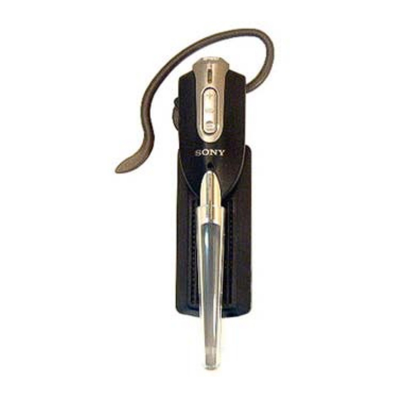
DR-BT1/BT1K
Photo : DR-BT1K
SPECIFICATIONS
Microphone
Type:
Unit:
Output impedance:
Open circuit voltage level: -42 dB(0 dB = 1 V/Pa)
Effective frequency range: 100 – 5,000 Hz
Bluetooth earset adaptor DRC-BT1 (BT1K only)
Supported Bluetooth Profiles:
Power source:
Typical Talk time:
Typical Standby Time:
Cord:
Plug:
Mass:
Design and specifications are subject to change without notice.
BLUETOOTH EARSET SYSTEM
US Model
Flexible pipe microphone
Electret condenser
Under 2.2 kΩ
Headset Profile
DC 1.2 V: Built-in Ni-MH rechargeable
battery
5 hours
100 hours
0.20 m (Max. stretch length 0.7m)
2.5 mm tri-pole plug
Approx. 35 g (without cord)
Advertisement
Table of Contents

Related Manuals for Sony DR-BT1

Summary of Contents for Sony DR-BT1
- Page 1 Coil) Sensitivity: 104 dB/mW 16 Ω at 1 kHz Impedance: Power handling capacity: 50 mW (IEC) Reproduction frequency range: 50 – 20,000 Hz BLUETOOTH EARSET SYSTEM Sony Corporation 9-879-223-02 Personal Audio Company 2005A02-1 Published by Sony Engineering Corporation © 2005.01...
-
Page 2: Table Of Contents
DR-BT1/BT1K TABLE OF CONTENTS 1. SERVICING NOTES Notes on chip component replacement ............3 • Never reuse a disconnected chip component. • Notice that the minus side of a tantalum capacitor may be 2. GENERAL ................3 damaged by heat. -
Page 3: Servicing Notes
DR-BT1/BT1K SECTION 1 SERVICING NOTES In case of replacing a nickel hydrogen battery in the adaptor (BT-1K), replace two battery pads and a battery sheet at the same time. cabinet (lower) battery sheet two battery pads nickel hydrogen battery SECTION 2... -
Page 4: Diagrams
DR-BT1/BT1K SECTION 3 DIAGRAMS NOTE FOR PRINTED WIRING BOARDS AND SCHEMATIC DIAGRAMS. For schematic diagrams. For printed wiring boards. Note: Note: • All capacitors are in µF unless otherwise noted. (p: pF) • X : parts extracted from the component side. -
Page 5: Block Diagrams
DR-BT1/BT1K 3-1. BLOCK DIAGRAM HEAD SET ANT2 ANTENNA PIO4 VOL - PIO5 VOL + DELAY SWITCH 1 PIO11 (BT1 ONLY) CHARGER MULITI FUNCTION PIO3 MIC1 MIC_N P1O9 MOD2 RECEIVER/TRANSMITTER, MIC AMP,AF AMP, VDD_IO +2.8V REG. SPKR_P BLUETOOTH CONTROL VREG_IN RECHAGEABLE DC IN 4.5V... -
Page 6: Printed Wiring Boards - Headset Board
DR-BT1/BT1K 3-2. PRINTED WIRING BOARD – HEADSET BOARD – : Uses unleaded solder. RECHARGEABLE BATTERY ( LI-ION ) + 3.7V HEADSET BOARD CONNECTOR BOARD ( SIDE A ) ( SIDE A ) MULTI FUNCTION (11) (11) 1-864-044- 1-864-046- CONNECTOR BOARD... -
Page 7: Schematic Diagram - Headset Board
DR-BT1/BT1K 3-3. SCHEMATIC DIAGRAM – HEADSET BOARD – DR-BT1/BT1K... -
Page 8: Adaptor Board (Bt1K Only)
DR-BT1/BT1K 3-4. PRINTED WIRING BOARD – ADAPTOR BOARD (BT1K only)– : Uses unleaded solder. ADAPTOR BOARD ( SIDE A ) HEADSET (Page 6) (11) 1-864-045- ADAPTOR BOARD ( SIDE B ) Pairing / Power off POWER ON • Semiconductor Location Ref. -
Page 9: Schematic Diagram - Adaptor Board (Bt1K Only)
DR-BT1/BT1K 3-5. SCHEMATIC DIAGRAM – ADAPTOR BOARD (BT1K only)– DR-BT1/BT1K... -
Page 10: Charger Board (Bt1 Only)
DR-BT1/BT1K 3-6. PRINTED WIRING BOARD – CHARGER BOARD (BT1 only)– : Uses unleaded solder. CHERGER BOARD ( SIDE A ) HEADSET (Page 6) 1-864-045- (11) CHERGER BOARD ( SIDE B ) 4.5V 1-864-045- (11) DR-BT1/BT1K... -
Page 11: Schematic Diagram - Charger Board (Bt1 Only)
DR-BT1/BT1K 3-7. SCHEMATIC DIAGRAM – CHARGER BOARD (BT1 only)–... -
Page 12: Exploded Views
DR-BT1/BT1K SECTION 4 EXPLODED VIEWS NOTE: • The mechanical parts with no reference number • -XX, -X mean standardized parts, so they may in the exploded views are not supplied. have some differences from the original one. • Items marked “*” are not stocked since they are seldom required for routine service. -
Page 13: Adaptor Section (Bt1K)
DR-BT1/BT1K 4-2. ADAPTOR SECTION (BT1K) not supplied Ref. No. Part No. Description Remarks Ref. No. Part No. Description Remarks 1-756-499-21 BATTERY, NICKEL HYDROGEN 2-177-373-01 HOLDER, PIPE, MIC 2-342-355-01 SHEET, BATTERY 2-177-371-01 CABINET (UPPER) 2-177-372-01 CABINET (LOWER) 2-177-400-01 PLATE, LIGHT GUIDE... -
Page 14: Charger Section (Bt1)
DR-BT1/BT1K 4-3. CHARGER SECTION (BT1) Ref. No. Part No. Description Remarks Ref. No. Part No. Description Remarks 3-254-083-11 SCREW 2-177-373-01 HOLDER, PIPE, MIC 2-177-372-11 CABINET (LOWER) 2-177-371-11 CABINET (UPPER) A-1072-244-A CHARGER BOARD, COMPLETE... -
Page 15: Electrical Parts List
DR-BT1/BT1K SECTION 5 ADAPTOR ELECTRICAL PARTS LIST NOTE: The components identified by mark 0 • RESISTORS • Due to standardization, replacements in the or dotted line with mark 0 are critical All resistors are in ohms. parts list may be different from the parts for safety. - Page 16 DR-BT1/BT1K ADAPTOR CHARGER CONNECTOR HEADSET Ref. No. Part No. Description Remarks Ref. No. Part No. Description Remarks 8-729-928-27 TRANSISTOR DTA144EE < IC > 8-729-929-26 TRANSISTOR DTC114TE 6-706-809-01 IC BQ24014DRCR < RESISTOR > < JACK > 1-218-977-11 RES-CHIP 100K 1/16W 1-750-849-21 JACK, EXTERNAL POWER (DC IN 4.5V)
- Page 17 DR-BT1/BT1K Ver. 1.1 HEADSET Ref. No. Part No. Description Remarks < COIL > 1-400-786-21 INDUCTOR 22uH 1-218-990-11 SHORT CHIP 1-164-860-11 CERAMIC CHIP 27PF < TRANSISTOR > 8-729-928-90 TRANSISTOR DTC114EE 8-729-927-99 TRANSISTOR 2SC4617R 8-729-426-30 TRANSISTOR XP1213-TXE < RESISTOR > 1-218-977-11 RES-CHIP...
- Page 18 DR-BT1/BT1K REVISION HISTORY Clicking the version allows you to jump to the revised page. Also, clicking the version at the upper right on the revised page allows you to jump to the next revised page. Ver. Date Description of Revision 2004.10...
Need help?
Do you have a question about the DR-BT1 and is the answer not in the manual?
Questions and answers