Advertisement
Quick Links
Part Number CRECOMZR009A00 and CRECOMZR011A00
GENERAL
IMPORTANT: Read these instructions completely
before attempting to install the accessory Economizer.
The accessory Economizer package uses microprocessor-
based controls to sequence mechanical cooling with cool out-
door air (free cooling) to satisfy the cooling load and minimize
energy consumption. Free cooling can be used alone or in
conjunction with mechanical cooling.
The standard economizer uses an outdoor-air temperature
sensor to sense outdoor-air temperature. When the outdoor-air
temperature is between two configurable ambient temperatures,
the economizer is allowed to cool. These temperature configura-
tions are the Economizer High Temperature Lockout (ECL.H)
and the Economizer Low Temperature Lockout (ECL.L). The
economizer will provide cooling when the outdoor temperature
is suitable as defined above by the lockout settings and if either
a thermostat or a space temperature probe has signaled a cooling
demand. In addition, if an outdoor enthalpy sensor accessory
has been installed, then the enthalpy reading must also be "low"
before economizer cooling can occur.
When free cooling is available, the Economizer sequences
free cooling with up to three stages of mechanical cooling to
maintain comfort in the space. When free cooling is not avail-
able, the Economizer modulates to an adjustable minimum
position to maintain a supply of fresh air entering the building.
Optional barometric relief dampers provide natural building
pressurization control. An optional power exhaust system is
available for jobs requiring greater relief.
PACKAGE USAGE AND CONTENTS
48/50HG UNIT SIZE
PACKAGE NO.
50TG500288
50TG400612
50TG400620
50TG500596
50TG400517
KH03DU350
014-024
—
(CRECOMZR009A00)
—
—
—
—
—
50TG5000720
50TG4000612
50TG4000620
50TG5000596
50TG4001186
KH03DU350
028
—
(CRECOMZR011A00)
—
—
—
—
—
Manufacturer reserves the right to discontinue, or change at any time, specifications or designs without notice and without incurring obligations.
PC 111
Book 1
1
4
4
Tab
1a 1b 6a 6b
Installation Instructions
QTY
CONTENTS
1
Economizer Assembly
1
Wire Harness
1
Wire Harness
1
Control Board
1
Block-Off Panel
3
Filters
1
Plastic Bushing
10
1
/
-14
5
/
-in. Screw
4
8
#14-10
7
/
-in. Washer Head
8
4
Screw
5
#6-20
3
/
-in. Pan Head Screw
4
4
8-in. Wire Tie
6
15-in. Wire Tie
1
Economizer Assembly
1
Wire Harness
1
Wire Harness
1
Control Board
1
Block-Off Panel
3
Filters
1
Plastic Bushing
10
1
/
-14
5
/
-in. Screw
4
8
#14-10
7
/
-in. Washer Head
8
4
Screw
5
#6-20
3
/
-in. Pan Head Screw
4
4
8-in. Wire Tie
6
15-in. Wire Tie
Catalog No. 534-80034
Printed in U.S.A.
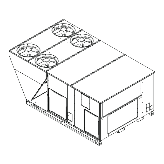
Large Rooftop Units
Accessory Economizer Package
SAFETY CONSIDERATIONS
Installation and servicing of air-conditioning equipment can
be hazardous due to system pressure and electrical compo-
nents. Only trained and qualified service personnel should
install, repair, or service air-conditioning equipment.
Untrained personnel can perform basic maintenance func-
tions of cleaning coils and filters and replacing filters. All other
operations should be performed by trained service personnel.
When working on air-conditioning equipment, observe precau-
tions in the literature, tags and labels attached to the unit, and
other safety precautions that may apply.
Follow all safety codes. Wear safety glasses and work
gloves. Use quenching cloth for unbrazing operations. Have
fire extinguishers available for all brazing operations
IMPORTANT: Do not adjust the damper assembly.
the motor and damper have been pre-set and adjusted
for proper operation.
Turn off unit power and lock out. Electrical shock and per-
sonal injury could result.
1. Remove two manual dampers and one mist eliminating
filter from the outdoor air hood in the return end of unit.
(See Fig. 1.) Save the screws to use later.
2. Remove the side panel on the return end of the unit to ex-
pose the return section of the unit. Save the screws for use
later when replacing the panel. The inside of the unit will
contain a frame for installing the economizer as shown in
Fig. 2.
Cover the duct opening as a precaution so objects cannot
fall into the return duct opening.
3. Remove the frame support brackets from both sides of
the frame inside the unit. Save the screws for use later.
4. Uncrate the economizer assembly. Position the damper
assembly so that it will rest on the angle bracket support
at the bottom of the economizer frame inside the unit.
Slide the economizer into the unit. (See Fig. 3.) Secure
the damper assembly to the frame using the
provided.
5. Install one of the plastic bushings, supplied with the ac-
cessory, into the wire hole in the damper frame at the ac-
tuator side of the unit. (See Fig. 4.)
Form 48/50HG-5SI
48/50HG014-028
INSTALLATION
1
Pg 1
6-01
/
-in. screws
4
Replaces: New
Advertisement

Related Manuals for Carrier 48HG014-028


Summary of Contents for Carrier 48HG014-028
-
Page 1: Installation Instructions
48/50HG014-028 Large Rooftop Units Accessory Economizer Package Installation Instructions Part Number CRECOMZR009A00 and CRECOMZR011A00 GENERAL SAFETY CONSIDERATIONS Installation and servicing of air-conditioning equipment can IMPORTANT: Read these instructions completely be hazardous due to system pressure and electrical compo- before attempting to install the accessory Economizer. nents. - Page 2 6. Install the wire harness (P/N 50TG400620). The motor through the plastic bushing, being careful not to damage plug should be located at the actuator side of the unit and the wires. Route the harness across the back of the top enough slack left on the motor end so that the plug can be member of the frame as shown and attach to the frame us- disconnected for easy service if required.
- Page 3 7. Connect the motor plug to the plug provided with the har- 10. Secure the partition to the frame using the screws saved ness. Be sure the wires will not interfere with any moving from Step 3, at the edges of the partition as shown in parts.
- Page 4 Fig. 8 — Economizer Board Mounting Location Fig. 9 — Economizer Control Board YELLOW LED - RED LED-STATUS GREEN LED- MAIN BASE BOARD CCN (CARRIER COMFORT NETWORK) PART NUMBER LEN (LOCAL EQUIPTMENT NETWORK) INSTANCE JUMPER CEPL130346-01 STATUS Fig. 10 — Main Base Board...
-
Page 5: Wire Routing
16. Connect the air quality plug marked “ECB-J5” from the pins 16 through 18. Connect the plug marked “ECB-J7” unit electrical harness into the Economizer Control Board to the J7 plug on the Economizer Control Board. plug J5. Be sure to connect the plug with the proper orien- 20. - Page 6 24. The ComfortLink™ control can now be configured to op- Economizer High Temperature Lockout setting (ECL.H) erate the economizer. To do this the unit must be config- and press ENTER twice. Use the arrow keys to increase ured for Economizer Equipped (default is NO). The de- or decrease the economizer lockout temperature and press fault settings are: Minimum Outdoor Air Percentage set- and then...
-
Page 7: Economizer Troubleshooting
Economizer does not return Unit is operating under free cooling Economizer is operating correctly to minimum position Damper does not close on Damper is jammed Identify the obstruction and safely remove power loss LEGEND CCN — Carrier Comfort Network — Indoor Air Quality... - Page 8 3 4 . 3 5 . 3 6 . 3 7 . Copyright 2001 Carrier Corporation Manufacturer reserves the right to discontinue, or change at any time, specifications or designs without notice and without incurring obligations. Book 1 PC 111 Catalog No.
Need help?
Do you have a question about the 48HG014-028 and is the answer not in the manual?
Questions and answers