
Related Manuals for GRAUPNER Alpha 110 Q


Summary of Contents for GRAUPNER Alpha 110 Q
- Page 1 Manual Alpha 110 Q Quadcopter S5012.RFH (Copter) S5012.RTF (Copter with transmitter) S5012.FPV (Copter with camera) S5012.FPVRTF (Copter with camera and transmitter)
- Page 2 2 / 28 S5012_Alpha_110_jh_V1...
-
Page 3: Table Of Contents
Index Introduction ................4 Service Centre ..............4 Intended use ................5 Copter Alpha 110Q .............5 Transmitter MZ-8 (only by S5012.RTF) ........5 Package content ..............6 Technical Data ..............6 Symbols explication ............7 Safety notes .................7 Charging the battery ............11 Transmitter power supply ..........11 Transmitter description (only by version S5012.RTF) ..12 Control elements on the transmitter ........12 Mode setting ..............13 Preparation before use .............14... -
Page 4: Introduction
Alpha 110 Quadcopter and first of all to safely control your mod- els. If you experience any trouble during operation, take the instructions to help or ask your dealer or Graupner Service Cen- tre. Due to technical changes, the information may be changed in this manual without prior notice. -
Page 5: Intended Use
Read through this entire manual before you attempt to assem- ble or use or use the Alpha 110 Quadcopter. Graupner/SJ constantly works on the development of all prod- ucts; we reserve the right to change the item, its technology and equipment. -
Page 6: Package Content
Package content S5012.RFH Alpha 110 Quadcopter Propellers Battery, battery charger Manual S5012.RTF Alpha 110 Quadcopter Propellers Battery, battery charger S1008 MZ-8 HoTT transmitter Manual S5012.FPV Alpha 110 Quadcopter with camera and video transmitter Propellers Battery, battery charger Manual S5012.FPVRTF Alpha 110 Quadcopter with camera and video transmitter S1008 MZ-8 HoTT transmitter Propellers Battery, battery charger... -
Page 7: Symbols Explication
Due to safety and licensing reasons (CE), any unauthorized reconstruction and/or modification of the product is prohibited. Only use the components and spare parts that we recommend. Always use matching, original Graupner plug-in connections of the same design and material. 7 / 28... - Page 8 Make sure that all of the plug-in connections are tight. When dis- connecting the plug-in connections, do not pull the cables. Protect the Copter from dust, dirt, moisture and other foreign parts. It must be protected from vibration as well as excessive heat or cold.
- Page 9 Storage LiPo batteries should be stored with a voltage of about 3,8V per cell. If the cell voltage falls below 3 V, then the battery must be necessarily charged. Deep discharge and storage in discharge status (cell voltage < 3V) make the battery useless. For transport and storage the LiPo batteries should be placed in a safety bag e.g.
- Page 10 The charger and the battery to be charged must be placed on a non-combustible, heat-resistant and non-conducting surface during operation. Do not use the charger near easily flammable materials. Always disconnect the charger from the power supply when it is not in use.
-
Page 11: Charging The Battery
Charging the battery Plug the USB connector of the included charger to a suitable 5 V port. 1. The LED on the charger will light green. 2. Plug the battery connector to the charger charging port. 3. The LED will turn from green (stand by mode) to red (charge mode). -
Page 12: Transmitter Description (Only By Version S5012.Rtf)
Transmitter description (only by version S5012.RTF) Control elements on the transmitter Front side mz-8 POWER SPEED SNAP RECORD Motor-off switch LED, yellow (indicates motor-off) on: Motor stop LED, red (indicates camera recording) blinking: Recording LED, green (if off indicates: Attitude mode, if on: Rate mode) LED, red (indicates status and binding) on: bound* Switch for Attitude and Rate mode Right control stick... -
Page 13: Mode Setting
You can find the software as free download on the mz-8 HoTT item page on www.graupner.de. If you have the mode 1 version, you can change your transmit- ter into mode 3 through the software. -
Page 14: Preparation Before Use
Controls directions Mode 3 - 4 MODE 3 (Throttle/Pitch right) MODE 4 (Throttle/Pitch left) Nick forward Throttle full Throttle full Nick forward Nick backward Motor idle Motor idle Nick backward Preparation before use The following components are required to use the model: Trans- mitter HoTT (MZ-8 / MX-12 / MZ-12 or higher) MZ-8 included by S5012.RTF. -
Page 15: Range Test
5 and about 10 m. Perform the range test for the Graupner-HoTT system according to the following instructions. It is useful to have an assistant to help you with the range test. -
Page 16: Example Flight Control Mode 1
Example flight control MODE 1 Climb - Sink mz-8 POWER SPEED SNAP RECORD Roll to the right and left mz-8 POWER SPEED SNAP RECORD Turn on its own axis mz-8 POWER SPEED SNAP RECORD 16 / 28 S5012_Alpha_110_jh_V1... -
Page 17: Example Flight Control Mode 2
Forward and backward mz-8 POWER SPEED SNAP RECORD Example flight control MODE 2 Climb - Sink mz-8 POWER SPEED SNAP RECORD Turn on its own axis mz-8 POWER SPEED SNAP RECORD 17 / 28 S5012_Alpha_110_jh_V1... - Page 18 Roll to the right and left mz-8 POWER SPEED SNAP RECORD Forward and backward mz-8 POWER SPEED SNAP RECORD 18 / 28 S5012_Alpha_110_jh_V1...
-
Page 19: Stick Calibration
Stick calibration If the center position of your self-neutralizing control stick does not precisely correspond to 0% control travel, you can check and correct it as follows. Stick calibration step by step: • Bring the transmitter to the programming mode by pushing and holding the left stick while switching on the transmitter. -
Page 20: Installing The Propellers
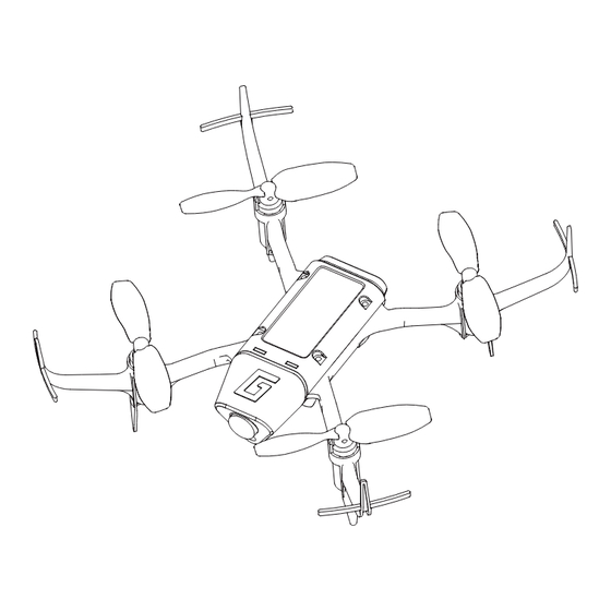
Installing the propellers CAUTION Risk of injury through rotating propellers by motors start. Always unplug the connector to the battery before working on the pro- pellers. Install the propellers as shown in the picture below. Pay atten- tion to install the proper propeller to each motor. The propeller rotation sense is written on the propeller (R/L)! The image rep- resents the copter seen from the top. -
Page 21: First Flight
First flight Choose a free area for your first flight. Select always first the Atti- tude mode, because the Copter is thus easier to control and to become familiar with the flight characteristics of the Alpha 110Q. Proceed carefully and responsibly. Start and land always in Atti- tude mode. -
Page 22: Camera Function By Version S 5012.Fpv
Camera function by version S 5012.FPV Through the installed camera and the video transmitter is emit- ted a video signal. The transmission starts as soon as you con- nect the copter battery. Scan the transmission signal of the cop- ter in your video goggles or video monitor. The video channel switching will be described in the next sec- tion Special functions. -
Page 23: Receiver's Base Settings
The S5012.RFH version has a big white LED on the front. To LED On/Off (Version S5012.RFH) switch the LED on program a mixer on your transmitter to chan- nel 6 with -100%. With the LED on the Auto-flip function is not available. -
Page 24: Roll And Nick Setting
Finally complete the procedure for yaw: on the transmitter, briefly set the yaw command fully to the right. Turn the copter so that the nose turns more than 45 degrees to the right; the axis is dis- played, the field is no longer highlighted and identification of this axis is complete. -
Page 25: Multicopter Yaw Settings
POWER2SENS.: Very strong drives can lead to oscillating at full throttle. This parameter allows you to set a kind of gyro suppression. Higher values result in an increased gyro suppression towards full throt- tle. Only for attitude mode ROLL/NICK I Set the I component of the Attitude mode. -
Page 26: Replacement Parts
Download area for the related products at www.graupner.de. Declaration of conformity S5012 Alpha 110Q Graupner/SJ declares that the product is conform to EU norms. EN 300 440-1 V1.6.1; EN 300 440-2 V1.4.1 3.2; EN 301 489-1 V1.9.2; EN 301 489-3 V1.6.1 3.1 EN 62479: 2010 3.1... -
Page 27: Notes On Environmental Protection
The cur- rent version can be found on the Internet at www.graupner.de the relevant product page. In addition, the company Graupner has no responsibility or liability for any errors or inaccuracies that may appear in construction or operation manuals.
Need help?
Do you have a question about the Alpha 110 Q and is the answer not in the manual?
Questions and answers