Table of Contents
Advertisement
Quick Links
Advertisement
Table of Contents

Related Manuals for Asus Z97-PRO GAMER


Summary of Contents for Asus Z97-PRO GAMER
- Page 1 Z97-PRO GAMER...
- Page 2 Product warranty or service will not be extended if: (1) the product is repaired, modified or altered, unless such repair, modification of alteration is authorized in writing by ASUS; or (2) the serial number of the product is defaced or missing.
-
Page 3: Table Of Contents
Contents Safety information ..................iv About this guide ..................iv Package contents ..................vi Z97-PRO GAMER specifications summary ..........vi Chapter 1: Product introduction Before you proceed ..............1-1 Motherboard overview ..............1-1 Central Processing Unit (CPU) ........... 1-3 System memory ................1-7 Expansion slots ................ -
Page 4: Safety Information
Safety information Electrical safety • To prevent electrical shock hazard, disconnect the power cable from the electrical outlet before relocating the system. • When adding or removing devices to or from the system, ensure that the power cables for the devices are unplugged before the signal cables are connected. If possible, disconnect all power cables from the existing system before you add a device. -
Page 5: Conventions Used In This Guide
Refer to the following sources for additional information and for product and software updates. ASUS websites The ASUS website provides updated information on ASUS hardware and software products. Refer to the ASUS contact information. Optional documentation Your product package may include optional documentation, such as warranty flyers, that may have been added by your dealer. -
Page 6: Package Contents
* Hyper DIMM support is subject to the physical characteristics of individual CPUs. Please refer to Memory QVL (Qualified Vendors List) for details. ** Refer to www.asus.com for the latest Memory QVL (Qualified Vendors List). Integrated graphics processor - Intel HD Graphics support ®... -
Page 7: Performance Optimization
- 6 x USB 3.0 / 2.0 ports* (2 ports at mid-board, 4 ports at rear panel, blue) - 8 x USB 2.0 ports (6 ports at mid-board, 2 ports at rear panel) * with ASUS USB 3.0 Boost support Gamer’s Guardian - ESD Guards on VGA, LAN, Audio, KBMS and USB 3.0/ 2.0 ports... - Page 8 Z97-PRO GAMER specifications summary Interactive HomeCloud Media Streamer - Pipe music or movies from your PC to a smart TV - Media Streamer app for portable smartphone/tablet, supporting iOS7 and Android 4.0 system Gaming Scenario Steam support - Compatible with the most fun gaming platform under Windows system...
- Page 9 1 x 8-pin ATX 12V power connector 64 Mb Flash ROM, UEFI AMI BIOS, PnP, DMI 2.7, WfM2.0, SM BIOS 2.8, ACPI 5.0, Multi-language BIOS, ASUS EZ Flash 2, ASUS CrashFree BIOS BIOS features 3, F11 EZ Tuning Wizard, F6 Qfan Control, F3 My Favorites, Quick Note,...
-
Page 11: Chapter 1: Product Introduction
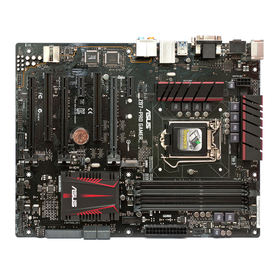
When installing the motherboard, place it into the chassis in the correct orientation. The edge with external ports goes to the rear part of the chassis as indicated in the image. 1.2.2 Screw holes Place eight screws into the holes indicated by circles to secure the motherboard to the chassis. Do not overtighten the screws! Doing so can damage the motherboard. ASUS Z97-PRO GAMER... -
Page 12: Motherboard Layout
Z97-PRO GAMER Place this side towards the rear of the chassis 1.2.3 Motherboard layout 24.4cm(9.6in) KBMS_USB78 CPU_FAN DIGI +VRM CPU_OPT ATX12V 1442K CHA_FAN3 LGA1150 USB3_56 LAN_USB3_34 DRAM_LED Intel I218V CHA_FAN1 CPU_LED AUDIO Z97-PRO GAMER PCIEX1_1 VGA_LED Super PCIEX16_1 PCI1 Intel ®... -
Page 13: Central Processing Unit (Cpu)
12. Serial port connectors (10-1 pin COM) 1-24 13. TPM connector (20-1 pin TPM) 1-24 14. Thermal sensor connector (2-pin T_SENSOR) 1-31 15. Clear RTC RAM (3-pin CLRTC) 1-21 16. Digital audio connector (4-1 pin SPDIF_OUT) 1-27 17. Front panel audio connector (10-1 pin AAFP) 1-27 Central Processing Unit (CPU) This motherboard comes with a surface mount LGA1150 socket designed for the 4th Generation, New 4th Generation and 5th Generation Intel Core™ i7 / Core™ i5 / Core™ i3, ® Pentium , and Celeron processors. ® ® Z97-PRO GAMER Z97-PRO GAMER CPU socket LGA1150 ASUS Z97-PRO GAMER... -
Page 14: Installing The Cpu
Unplug all power cables before installing the CPU. • Ensure that you install the correct CPU designed for the LGA1150 socket only. DO NOT install a CPU designed for LGA1155 and LGA1156 sockets on the LGA1150 socket. • Upon purchase of the motherboard, ensure that the PnP cap is on the socket and the socket contacts are not bent. Contact your retailer immediately if the PnP cap is missing, or if you see any damage to the PnP cap/socket contacts/motherboard components. • Keep the cap after installing the motherboard. ASUS will process Return Merchandise Authorization (RMA) requests only if the motherboard comes with the cap on the LGA1150 socket. • The product warranty does not cover damage to the socket contacts resulting from incorrect CPU installation/removal, or misplacement/loss/incorrect removal of the PnP cap. 1.3.1 Installing the CPU Chapter 1: Product introduction... -
Page 15: Cpu Heatsink And Fan Assembly Installation
1.3.2 CPU heatsink and fan assembly installation Apply the Thermal Interface Material to the CPU heatsink and CPU before you install the heatsink and fan if necessary. ASUS Z97-PRO GAMER... - Page 16 To install the CPU heatsink and fan assembly To uninstall the CPU heatsink and fan assembly Chapter 1: Product introduction...
-
Page 17: System Memory
System memory 1.4.1 Overview This motherboard comes with four Double Data Rate 3 (DDR3) Dual Inline Memory Module (DIMM) sockets. A DDR3 module is notched differently from a DDR or DDR2 module. DO NOT install a DDR or DDR2 memory module to the DDR3 slot. According to Intel CPU spec, DIMM voltage below 1.65 V is recommended to protect the ® CPU. Z97-PRO GAMER Z97-PRO GAMER 240-pin DDR3 DIMM sockets 1.4.2 Memory configurations You may install 2 GB, 4 GB, and 8 GB unbuffered non-ECC DDR3 DIMMs into the DIMM sockets. You can refer to the recommended memory population below. Recommended memory configurations ASUS Z97-PRO GAMER... - Page 18 Ai Tweaker menu for manual memory frequency adjustment. • Memory modules with memory frequency higher than 2133MHz and their corresponding timing or the loaded XMP profile is not the JEDEC memory standard. The stability and compatibility of the memory modules depend on the CPU’s capabilities and other installed devices. • For system stability, use a more efficient memory cooling system to support a full memory load (4 DIMMs). Z97-PRO GAMER motherboard memory Qualified Vendors Lists (QVL) DDR3 3200 (O.C.) MHz capability DIMM socket support Chip Chip (Optional) Vendors Part No. Size SS/DS...
- Page 19 1.65V • CORSAIR CMD16GX3M4A2800C11(XMP) 16GB (4x 4GB) 11-14-14-35 1.65V • • CORSAIR CMD16GX3M4A2800C12(XMP) 16GB (4x 4GB) 12-14-14-36 1.65V • • CORSAIR CMY16GX3M4A2800C12R(XMP) 16GB (4x 4GB) 12-14-14-36 1.65V • • KINGSTON KHX28C12T2K2/8X 8GB (2x 4GB) 12-14-14-32 1.65V • • Team TXD38G2800HC12DBK(XMP) 32GB (4 x 8GB) 11-14-14-35 1.65V • • ASUS Z97-PRO GAMER...
- Page 20 DDR3 2666 (O.C.) MHz capability Vendors Part No. Size Chip Chip Timing Voltage DIMM socket support Brand (Optional) 1 DIMM 2 DIMMs 4 DIMMs Apacer 78.BAGFF.AFC0C(XMP) 8GB (2x4GB) 12-13-13-35 • • • Apacer 78.BAGFR.AFD0C(XMP) 8GB (2x4GB) 12-13-13-35 • • • Apacer 78.CAGFF.AFD0C(XMP) 16GB (2x8GB) 12-13-13-35 •...
- Page 21 Chip NO. Timing Voltage Brand 1 DIMM 2 DIMMs 4 DIMMs AEXEA AXA3ES4GK2000LG28V(XMP) 4GB (2x2GB) 1.65V • • • H5TQ2G83 Asint SLA302G08-ML2HB(XMP) 4GB Hynix 9-9-9-27 - • • • BFRH9C GEIL GUP34GB2000C9DC(XMP) 4GB (2x2GB) 9-9-9-28 1.65V • • • ASUS Z97-PRO GAMER 1-11...
- Page 22 DDR3 1866 (O.C.) MHz capability DIMM socket support Chip Chip (Optional) Vendors Part No. Size NO. Timing Voltage Brand 1 DIMM 2 DIMMs 4 DIMMs CMD16GX3M2A1866C9 (Ver5.29) CORSAIR 16GB ( 2x 8GB ) DS 9-9-9-27 • • (XMP) CMD16GX3M4A1866C9 (Ver4.13) CORSAIR 16GB ( 4x 4GB ) DS 9-10-9-27 • • •...
- Page 23 • (XMP) 4GB ) CMZ8GX3M1A1600C10 (Ver3.23) 8GB ( 1x CORSAIR DS - 10-10-10-27 1.5 • • (XMP) 8GB ) CMZ8GX3M1A1600C10 (Ver8.21) 8GB ( 1x CORSAIR DS - 10-10-10-27 1.5 • • (XMP) 8GB ) 8GB ( 2x CORSAIR CMZ8GX3M2A1600C8(XMP) DS - 8-8-8-24 • • • 4GB ) (continued on the next page) ASUS Z97-PRO GAMER 1-13...
- Page 24 DDR3 1600 MHz capability DIMM socket support (Optional) Vendors Part No. Size DS Chip Brand Chip NO. Timing Voltage 1 DIMM 2 DIMMs 4 DIMMs BLS4G3D1609DS1S00.16FMR Crucial DS - 9-9-9-24 • • • (XMP) BLT4G3D1608DT1TX0.16FM Crucial 4GB DS - 8-8-8-24 •...
- Page 25 • • • 4GB ) 4GB ( 2x GEIL GG34GB1333C9DC DS GEIL GL1L128M88BA15B 9-9-9-24 • • • 2GB ) 4GB ( 2x GEIL GVP34GB1333C9DC DS - 9-9-9-24 • • • 2GB ) 8GB ( 2x GEIL GVP38GB1333C9DC DS - 9-9-9-24 • • • 4GB ) (continued on the next page) ASUS Z97-PRO GAMER 1-15...
- Page 26 84E44G93UM-13BPSYW UMAX U2S96D30TP-13 • • • 9-24 1333-9-9- UMAX 84E48G93UM-13BPSYW DS UMAX U2S96D30TP-13 • • • 9-24 • SS: Single-sided / DS: Double-sided DIMM support: • 2 DIMMs: S upports two (2) modules inserted into either the black slots or the gray slots as one pair of Dual-channel memory configuration. 4 DIMMs: S upports four (4) modules inserted into both the gray and black slots as • two pairs of Dual-channel memory configuration • Visit the ASUS website at www.asus.com for the latest QVL. 1-16 Chapter 1: Product introduction...
- Page 27 1.4.3 Installing a DIMM To remove a DIMM ASUS Z97-PRO GAMER 1-17...
-
Page 28: Expansion Slots
Expansion slots In the future, you may need to install expansion cards. The following sub-sections describe the slots and the expansion cards that they support. Unplug the power cord before adding or removing expansion cards. Failure to do so may cause you physical injury and damage motherboard components. 1.5.1 Installing an expansion card To install an expansion card: Before installing the expansion card, read the documentation that came with it and make the necessary hardware settings for the card. Remove the system unit cover (if your motherboard is already installed in a chassis). - Page 29 PCI Express operating mode VGA configuration PCIe 3.0/2.0 x16_1 (gray) PCIe 3.0/2.0 x16_2 PCIe 2.0 x16_3 x16 (Recommended for Single VGA/PCIe card single VGA card) Dual VGA/PCIe card • In single VGA card mode, use the PCIe 3.0/2.0 x16_1 slot (gray) for a PCI Express x16 graphics card to get better performance. • We recommend that you provide sufficient power when running SLI™ or CrossFireX™ mode. See page 1-26 for details. • Connect a chassis fan to the motherboard connector labeled CHA_FAN1/2/3 when using multiple graphics cards for better thermal environment. ASUS Z97-PRO GAMER 1-19...
- Page 30 IRQ assignments for this motherboard I.G.D. Shared – – – – – – – HD Audio 1 Controller – – – – – – Shared – EHCI 1 Controller – – – – – – – Shared EHCI 2 Controller Shared – – – – – – –...
-
Page 31: Jumpers
Jumpers Clear RTC RAM (3-pin CLRTC) This jumper allows you to clear the Real Time Clock (RTC) RAM in CMOS. You can clear the CMOS memory of date, time, and system setup parameters by erasing the CMOS RTC RAM data. The onboard button cell battery powers the RAM data in CMOS, which include system setup information such as system passwords. Z97-PRO GAMER CLRTC Normal Clear RTC (Default) Z97-PRO GAMER Clear RTC RAM To erase the RTC RAM: Turn OFF the computer and unplug the power cord. Move the jumper cap from pins 1-2 (default) to pins 2-3. Keep the cap on pins 2-3 for about 5-10 seconds, then move the cap back to pins 1-2. Plug the power cord and turn ON the computer. Hold down the <Del> key during the boot process and enter BIOS setup to re- enter data. Except when clearing the RTC RAM, never remove the cap on CLRTC jumper default position. Removing the cap will cause system boot failure! • If the steps above do not help, remove the onboard battery and move the jumper again to clear the CMOS RTC RAM data. After clearing the CMOS, reinstall the battery. -
Page 32: Connectors
Connectors 1.7.1 Rear panel connectors PS/2 Mouse/Keyboard combo port. This port connects to a PS/2 mouse or PS/2 keyboard. Optical S/PDIF out port. This port allows you to connect your PC to amplified speakers, headphones, or Sony/Phillips Digital Interconnect Format (S/PDIF) compliant devices. Video Graphics Adapter (VGA) port. This 15-pin port is for a VGA monitor or other VGA-compatible devices. LAN (RJ-45) port. This port allows Gigabit connection to a Local Area Network (LAN) through a network hub. LAN port LED indications Activity Link Speed Activity/Link LED Speed LED Status Description Status... - Page 33 Headset Port 4-channel 6-channel 8-channel 2-channel Light Blue Line In Line In Line In Line In Lime Line Out Front Speaker Out Front Speaker Out Front Speaker Out Pink Mic In Mic In Mic In Mic In Orange – – Center/Subwoofer Center/Subwoofer Gray – – – Side Speaker Out Black – Rear Speaker Out Rear Speaker Out Rear Speaker Out ASUS Z97-PRO GAMER 1-23...
-
Page 34: Internal Connectors
1.7.2 Internal connectors Serial port connector (10-1 pin COM) This connector is for a serial (COM) port. Connect the serial port module cable to this connector, then install the module to a slot opening at the back of the system chassis. PIN 1 Z97-PRO GAMER Z97-PRO GAMER Serial port (COM) connector The COM module is purchased separately. TPM connector (20-1 pin TPM) This connector supports a Trusted Platform Module (TPM) system, which securely store keys, digital certificates, passwords and data. A TPM system also helps enhance the network security, protects digital identities, and ensures platform integrity. Z97-PRO GAMER PIN 1 Z97-PRO GAMER TPM connector 1-24 Chapter 1: Product introduction... - Page 35 Connect the fan cables to the fan connectors on the motherboard, ensuring that the black wire of each cable matches the ground pin of the connector. CPU_FAN CPU_OPT CHA_FAN3 CHA FAN PWR CHA FAN IN CHA_FAN1 CHA_FAN2 Z97-PRO GAMER Z97-PRO GAMER Fan connectors Do not forget to connect the fan cables to the fan connectors. Insufficient air flow inside the system may damage the motherboard components. These are not jumpers! Do not place jumper caps on the fan connectors! The CPU_FAN connector supports a CPU fan of maximum 1 A (12 W) fan power. • The CPU_FAN connector and CHA_FAN connectors support the ASUS FAN Xpert 3 feature. • The CPU fan connector detects the type of CPU fan installed and automatically switches the control modes. To configure the CPU fan’s control mode, go to Advanced >...
- Page 36 Power OK -5 Volts +5 Volts Z97-PRO GAMER +5 Volts PSON# +3 Volts -12 Volts +3 Volts +3 Volts PIN 1 Z97-PRO GAMER ATX power connectors • For a fully configured system, we recommend that you use a power supply unit (PSU) that complies with ATX 12 V Specification 2.0 (or later version) and provides a minimum power of 350 W. • DO NOT forget to connect the 4-pin/8-pin ATX +12V power plug. Otherwise, the system will not boot up. • We recommend that you use a PSU with higher power output when configuring a system with more power-consuming devices or when you intend to install additional devices. The system may become unstable or may not boot up if the power is...
- Page 37 This connector is for a chassis-mounted front panel audio I/O module that supports either HD Audio or legacy AC`97 audio standard. Connect one end of the front panel audio I/O module cable to this connector. AAFP Z97-PRO GAMER PIN 1 HD-audio-compliant Legacy AC’97 pin definition compliant definition Z97-PRO GAMER Front panel audio connector • We recommend that you connect a high-definition front panel audio module to this connector to avail of the motherboard’s high-definition audio capability. • If you want to connect a high-definition front panel audio module to this connector, set the Front Panel Type item in the BIOS setup to [HD]. If you want to connect an AC’97 front panel audio module to this connector, set the item to [AC97]. By default, this connector is set to [HD]. See section 2.6.7 Onboard Devices Configuration for details. Digital audio connector (4-1 pin SPDIF_OUT) This connector is for an additional Sony/Philips Digital Interface (S/PDIF) port. Connect...
- Page 38 IntA_P1_SSRX- IntA_P2_SSRX- IntA_P1_SSRX+ IntA_P2_SSRX+ IntA_P1_SSTX- IntA_P2_SSTX- IntA_P1_SSTX+ IntA_P2_SSTX+ IntA_P1_D- IntA_P2_D- IntA_P1_D+ IntA_P2_D+ Z97-PRO GAMER USB3.0 Front panel connector The USB 3.0 module is purchased separately. USB 2.0 connectors (10-1 pin USB910, USB1112, USB1314) These connectors are for USB 2.0 ports. Connect the USB module cable to any of these connectors, then install the module to a slot opening at the back of the system chassis. These USB connectors comply with USB 2.0 specifications and supports up to 480Mbps connection speed. USB1314 USB1112 USB910 Z97-PRO GAMER PIN 1 PIN 1 PIN 1 Z97-PRO GAMER USB2.0 connectors...
- Page 39 RSATA_RXP2 SATA6G_3 SATA6G_4 RSATA_TXP3 RSATA_TXP4 RSATA_TXN3 RSATA_TXN4 RSATA_RXN3 RSATA_RXN4 RSATA_RXP3 RSATA_RXP4 SATA6G_5 SATA6G_6 Z97-PRO GAMER Z97-PRO GAMER Intel SATA 6.0Gb/s connectors ® • These connectors are set to [AHCI] by default. If you intend to create a Serial ATA RAID set using these connectors, set the SATA Mode item in the BIOS to [RAID]. Refer to section 2.6.3 PCH Storage Configuration for details. • Before creating a RAID set, refer to the manual bundled in the motherboard support DVD. The SATAEXPRESS connector can support one SATA Express device or two SATA devices. ASUS Z97-PRO GAMER 1-29...
-
Page 40: System Panel Connector (20-8 Pin Panel)
System panel connector (20-8 pin PANEL) This connector supports several chassis-mounted functions. +PWR_LED- SPEAKER Z97-PRO GAMER PANEL PIN 1 +HDD_LED- PWR_SW RESET Z97-PRO GAMER System panel connector • System power LED (2-pin +PWR_LED-) This 2-pin connector is for the system power LED. Connect the chassis power LED cable to this connector. The system power LED lights up when you turn on the system power, and blinks when the system is in sleep mode. • Hard disk drive activity LED (2-pin +HDD_LED-) This 2-pin connector is for the HDD Activity LED. Connect the HDD Activity LED cable to this connector. The HDD LED lights up or flashes when data is read from or written to the HDD. • System warning speaker (4-pin SPEAKER) This 4-pin connector is for the chassis-mounted system warning speaker. The speaker allows you to hear system beeps and warnings. - Page 41 UEFI operating system under RAID mode. ® The M.2 (NGFF) SSD module is purchased separately Thermal sensor connector (2-pin T_SENSOR) This connector is for the thermistor cable that allows you to monitor the temperature of your motherboard’s critical components and connected devices. Z97-PRO GAMER T_SENSOR1 PIN 1 SENSOR IN Z97-PRO GAMER Thermal sensor connector ASUS Z97-PRO GAMER 1-31...
-
Page 42: Onboard Leds
Standby Power LED (SB_PWR) The motherboard comes with a standby power LED that lights up to indicate that the system is ON, in sleep mode, or in soft-off mode. This is a reminder that you should shut down the system and unplug the power cable before removing or plugging in any motherboard component. The illustration below shows the location of the onboard LED. Z97-PRO GAMER SB_PWR Standby Power Powered Off Z97-PRO GAMER Onboard LED Q LEDs (BOOT_DEVICE_LED, VGA_LED, DRAM_LED, CPU_LED) Q LEDs check key components (CPU, DRAM, VGA card, and booting devices) in sequence during motherboard booting process. If an error is found, the corresponding LED flashes until the problem is solved. This user-friendly design provides an intuitive way to locate the root problem within seconds. DRAM_LED CPU_LED Z97-PRO GAMER... -
Page 43: Software Support
To run the Support DVD Place the Support DVD into the optical drive. If Autorun is enabled in your computer, the DVD automatically displays the lists of the unique features of your ASUS motherboard. Click the Drivers, Utilities, AHCI/RAID Driver, Manual, Contact, or Specials tabs to display their respective menus. The following screen is for reference only. Click an icon to display Support DVD/motherboard information Click an item to install If Autorun is NOT enabled in your computer, browse the contents of the Support DVD to locate the file ASSETUP.EXE from the BIN folder. Double-click the ASSETUP.EXE to run the DVD. ASUS Z97-PRO GAMER 1-33... - Page 44 1-34 Chapter 1: Product introduction...
-
Page 45: Chapter 2: Bios Information
DVD and a USB flash disk drive. Save a copy of the original motherboard BIOS file to a USB flash disk in case you need to restore the BIOS in the future. Copy the original motherboard BIOS using the ASUS Update utility. -
Page 46: Asus Ez Flash
2.1.2 ASUS EZ Flash 2 The ASUS EZ Flash 2 feature allows you to update the BIOS without using an OS-based utility. Before you start using this utility, download the latest BIOS file from the ASUS website at www.asus.com. To update the BIOS using EZ Flash 2: Insert the USB flash disk that contains the latest BIOS file to the USB port. -
Page 47: Asus Crashfree Bios 3 Utility
2.1.3 ASUS CrashFree BIOS 3 utility The ASUS CrashFree BIOS 3 is an auto recovery tool that allows you to restore the BIOS file when it fails or gets corrupted during the updating process. You can restore a corrupted BIOS file using the motherboard support DVD or a USB flash drive that contains the updated BIOS file. - Page 48 ENTER to select boot device ESC to boot using defaults P2: ST3808110AS (76319MB) aigo miniking (250MB) UEFI: (FAT) ASUS DRW-2014L1T(4458MB) P1: ASUS DRW-2014L1T(4458MB) UEFI: (FAT) aigo miniking (250MB) Enter Setup When the Boot Loader appears, press <Enter> within five (5) seconds to enter FreeDOS prompt.
- Page 49 DO NOT shut down or reset the system while updating the BIOS to prevent system boot failure. Ensure to load the BIOS default settings to ensure system compatibility and stability. Select the Load Optimized Defaults item under the Exit menu for more information. ASUS Z97-PRO GAMER...
-
Page 50: Bios Setup Program
The BIOS setup screens shown in this section are for reference only. Some screen displays may not be the same as what you see on your screen. • Visit the ASUS website at www.asus.com to download the latest BIOS file for this motherboard. •... - Page 51 Selects the boot device priority • The boot device options vary depending on the devices you installed to the system. • The Boot Menu(F8) button is available only when the boot device is installed to the system. ASUS Z97-PRO GAMER...
-
Page 52: Advanced Mode
Advanced Mode The Advanced Mode provides advanced options for experienced end-users to configure the BIOS settings. Refer to the following sections for the detailed configurations. To access the EZ Mode, press <F7>. Q-Fan control EZ Tuning Wizard MyFavorite Quick Note Language Hot Keys Menu bar... -
Page 53: Menu Bar
This button above the menu bar allows you to view and tweak the overclocking settings of your system. It also allows you to change the motherboard’s SATA mode from AHCI to RAID mode. Refer to section 2.2.4 EZ Tuning Wizard for more information. ASUS Z97-PRO GAMER... -
Page 54: Hot Keys
Quick Note (F9) This button above the menu bar allows you to key in notes of the activities that you have done in BIOS. • The Quick Note function does not support the following keyboard functions: delete, cut, copy and paste. •... -
Page 55: Qfan Control
Click to activate DC Mode Click to activate configured PWM Mode Click to apply the Select a profile to apply to fan setting your fans Click to undo the Click to go changes back to main menu ASUS Z97-PRO GAMER 2-11... - Page 56 Configuring fans manually Select Manual from the list of profiles to manually configure your fans’ operating speed. Click to manually configure Speed points your fans To configure your fans: Select the fan that you want to configure and to view its current status. Click and drag the speed points to adjust the fans’...
-
Page 57: Ez Tuning Wizard
Select the CPU fan type (Box cooler, Tower cooler, or Water cooler) that you installed then click Next. If you are not sure of the CPU fan type, click I’m not sure. The system automatically detects the CPU fan type. Click Next then click Yes to confirm auto-tuning. ASUS Z97-PRO GAMER 2-13... -
Page 58: Creating Raid
Creating RAID To create RAID: Press <F11> on your keyboard or click from the BIOS screen to open EZ Tuning Wizard screen. Click RAID then click Next. • Ensure that your HDDs have no existing RAID volumes. • Ensure to connect your HDDs to Intel SATA connectors. -
Page 59: My Favorites
• Configuration items such as Memory SPD Information, system time and date. Click Exit (ESC) or press <esc> key to close Setup Tree Map screen. Go to My Favorites menu to view the saved BIOS items. ASUS Z97-PRO GAMER 2-15... -
Page 60: Main Menu
Main menu The Main menu screen appears when you enter the Advanced Mode of the BIOS Setup program. The Main menu provides an overview of the basic system information and allows you to set the system date, time, language, and security settings. 2.4.1 System Language [English] Allows you to choose the BIOS language version from the options. -
Page 61: User Password
To clear the user password, follow the same steps as in changing a user password, but press <Enter> when prompted to create/confirm the password. After you clear the password, the User Password item on top of the screen shows Not Installed. ASUS Z97-PRO GAMER 2-17... -
Page 62: Ai Tweaker Menu
Ai Tweaker menu The Ai Tweaker menu items allow you to configure overclocking-related items. Be cautious when changing the settings of the Ai Tweaker menu items. Incorrect field values can cause the system to malfunction. The configuration options for this section vary depending on the CPU and DIMM model you installed on the motherboard. - Page 63 Memory Profile (X.M.P.) Technology, select this item to set the profiles supported by your memory modules for optimizing the system performance. The following items appear only when you set the Ai Overclocking Tuner to [Manual]. ASUS Z97-PRO GAMER 2-19...
- Page 64 BCLK Frequency. 2.5.2 ASUS MultiCore Enhancement [Auto] [Auto] This item allows you to maximize the oveclocking performance optimized by ASUS core ratio settings. [Disabled] This item allows you to set to default core ratio settings. 2.5.3 CPU Core Ratio [Auto] Allows you to set the CPU core ratio automatically or manually.
- Page 65 Allows you to set the CPU bus speed to DRAM speed ratio mode. [Auto] DRAM speed is set to the optimized settings. [100:133] The BCLK frequency to DRAM speed ratio is set to 100:133. [100:100] The BCLK frequency to DRAM speed ratio is set to 100:100. ASUS Z97-PRO GAMER 2-21...
-
Page 66: Dram Timing Control
2.5.11 EPU Power Saving Mode [Disabled] ASUS EPU (Energy Processing Unit) sets the CPU in its minimum power consumption settings. Enable this item to set lower CPU VCCIN and Vcore voltages and achieve the best energy saving condition. Configuration options: [Disabled] [Enabled] 2.5.12... - Page 67 Allows you to limit the Turbo Ratio’s time duration that exceeds the TDP (Thermal Design Power) for maximum performance. Use the <+> or <-> keys to adjust the value. The values range from 1 W to 4096 W. ASUS Z97-PRO GAMER 2-23...
- Page 68 Package Power Time Window [Auto] Also known as Power Limit 1, this item allows you to maintain the time window for Turbo Ratio over TDP (Thermal Design Power). Use the <+> or <-> keys to adjust the value. The values range from 1 to 127 in seconds. Short Duration Package Power Limit [Auto] Also known as Power Limit 2, this item allows you to provide rapid protection when the package power exceeds the Power Limit 1.
- Page 69 CPU Core Voltage [Auto] This item allows you to configure the amount of voltage fed to the CPU cores. Increase the voltage when setting a high Core Frequency value. Configuration options: [Auto] [Manual Mode] [Offset Mode] [Adaptive Mode] ASUS Z97-PRO GAMER 2-25...
- Page 70 • The following item appears only when you set the CPU Core Voltage to [Manual Mode]. • [Adaptive Mode] is available for some specific CPU types. CPU Core Voltage Override [Auto] Allows you to set the CPU Core Voltage override. Use the <+> or <-> keys to adjust the value.
- Page 71 This item appears only when you set the CPU Graphics Voltage to [Offset Mode] or [Adaptive Mode] and allows you to set the CPU graphics voltage offset. The values range from 0.001V to 0.999V with a 0.001V interval. ASUS Z97-PRO GAMER 2-27...
- Page 72 The following items appear only when you set the CPU Graphics Voltage to [Adaptive Mode]. Additional Turbo Mode CPU Graphics Voltage [Auto] This item appears only when you set the CPU Graphics Voltage to [Adaptive Mode] and allows you to set the additional turbo mode CPU graphics voltage. The values range from 0.001V to 1.920V with a 0.001V interval.
- Page 73 This item allows you to enhance the BCLK overclocking capability or reduce the EMI (electromagnetic disturbance) generated by the BCLK. Set this item to [Enabled] for EMI reduction, or set this item to [Disabled] to enhance BCLK overclocking. Configuration options: [Auto] [Disabled] [Enabled] ASUS Z97-PRO GAMER 2-29...
-
Page 74: Advanced Menu
Advanced menu The Advanced menu items allow you to change the settings for the CPU and other system devices. Be cautious when changing the settings of the Advanced menu items. Incorrect field values can cause the system to malfunction. 2.6.1 CPU Configuration The items in this menu show the CPU-related information that the BIOS automatically detects. - Page 75 This item allows you to automatically set the CPU cores to run faster than the base operating frequency when it is below the operating power, current and temperature specification limit. Configuration options: [Enabled] [Disabled] Turbo Mode is only available on selected CPU models only. ASUS Z97-PRO GAMER 2-31...
-
Page 76: Pch Configuration
CPU C-States [Auto] This item allows you to set the power saving of the CPU states. Configuration options: [Auto] [Disabled] [Enabled] The following items appear only when you set the CPU C-States to [Enabled]. Enhanced C1 state [Enabled] This item allows your CPU to reduce power consumption when the system is in idle mode. -
Page 77: Pch Storage Configuration
The system automatically adjust the SRIS (Separate Reference Clock Independent Spread Spectrum Clocking Architecture) support for connected SATA Express devices. [Disabled] Select this option for ASUS RUNWAY SATA Express bridge card. SATA Mode Selection [AHCI] Allows you to set the SATA configuration. [Disabled] Disables the SATA function. -
Page 78: System Agent Configuration
[AHCI] Set to [AHCI] when you want the SATA hard disk drives to use the AHCI (Advanced Host Controller Interface). The AHCI allows the onboard storage driver to enable advanced Serial ATA features that increases storage performance on random workloads by allowing the drive to internally optimize the order of commands. -
Page 79: Dmi Configuration
Disables this function. 2.6.5 USB Configuration The items in this menu allow you to change the USB-related features. The USB Devices item shows the auto-detected values. If no USB device is detected, the item shows None. ASUS Z97-PRO GAMER 2-35... -
Page 80: Platform Misc Configuration
Legacy USB Support [Enabled] [Enabled] Enables the support for USB devices on legacy operating systems (OS). [Disabled] The USB devices can be used only for the BIOS setup program. [Auto] Allows the system to detect the presence of USB devices at startup. If detected, the USB controller legacy mode is enabled. -
Page 81: Onboard Devices Configuration
ASPM to take effect. Configuration options: [Disabled] [L0s] [L1] [L0sL1] PEG ASPM Support [Disabled] This item allows you to select the ASPM state for energy-saving conditions, or use the ASUS optimized energy saving profile. Configuration options: [Disabled] [ASPM L0s] [L1] [L0sL1] [Auto] 2.6.7... -
Page 82: Serial Port Configuration
Intel LAN Controller [Enabled] Allows you to enable or disable the GbE controller. Configuration options: [Enabled] [Disabled] Intel LAN PXE Option ROM [Disabled] This item only appears when the item Intel LAN Controller is set to [Enabled]. This item allows you to enable or disable the Intel PXE Option ROM. Configuration options: [Enabled] [Disabled] Serial Port Configuration The sub-items in this menu allow you to set the serial port configuration. -
Page 83: Network Stack Configuration
This item allows user to disable or enable the Ipv4 PXE Boot support. Configuration options: [Disable Link] [Enabled] Ipv6 PXE Support [Enabled] This item allows user to disable or enable the Ipv6 PXE Boot support. Configuration options: [Disable Link] [Enabled] ASUS Z97-PRO GAMER 2-39... -
Page 84: Monitor Menu
Monitor menu The Monitor menu displays the system temperature/power status, and allows you to change the fan settings. Scroll down to display the following items: 2-40 Chapter 2: Getting started... - Page 85 CPU Input Voltage (VCCIN), CPU Core Voltage, 3.3V Voltage, 5V Voltage, 12V Voltage The onboard hardware monitor automatically detects the voltage output through the onboard voltage regulators. Select Ignore if you do not want to detect this item. ASUS Z97-PRO GAMER 2-41...
- Page 86 2.7.5 CPU Q-Fan Control [Auto] [Auto] Enables the CPU Q-Fan control for 4-pin CPU fan. [Disabled] Disables the CPU Q-Fan control feature. [PWM Mode] Enable the CPU Q-Fan control in PWM mode for 4-pin CPU fan. [DC Mode] Enable the CPU Q-Fan control in DC mode for 3-pin CPU fan. The following items appear only when you set CPU Q-Fan Control to [Auto], [PWM Mode] or [DC Mode].
- Page 87 Use the <+> or <-> keys to adjust the maximum chassis fan duty cycle. The values range from 60% to 100%. When the chassis temperature reaches the upper limit, the chassis fan will operate at the maximum duty cycle. ASUS Z97-PRO GAMER 2-43...
- Page 88 Chassis Fan 1/2/3 Middle Temperature [45] Use the <+> or <-> keys to set the value for Chassis Fan Middle Temperature. Chassis Fan 1/2/3 Middle Duty Cycle(%) [60] Use the <+> or <-> keys to adjust the chassis fan middle duty cycle. The values range from 60% to 100%.
-
Page 89: Boot Menu
Scroll down to display the following items: 2.8.1 Fast Boot [Enabled] [Enabled] Select to accelerate the boot speed. [Disabled] Select to go back to normal boot. The following five items appear when you set Fast Boot to [Enabled]. ASUS Z97-PRO GAMER 2-45... - Page 90 SATA Support [All Devices] [All Devices] All devices connected to SATA ports will be available during POST. This process will extend the POST time. [Hard Drive Only] Only hard drives connected to SATA ports will be detected during POST. Any hardware change will disable fast boot. [Boot Drive Only] Only boot drive connected to SATA ports will be detected during POST.
- Page 91 Option ROM Messages [Enabled] [Enabled] The option ROM messages will be shown during the POST (power-on self- test). [Disabled] Only the ASUS logo will be shown during the POST. 2.8.6 Interrupt 19 Capture [Disabled] [Enabled] Allows the option ROMs to trap Interrupt 19.
-
Page 92: Secure Boot
Launch CSM [Enabled] [Auto] The system automatically detects the bootable devices and the add-on devices. [Enabled] For better compatibility, enable the CSM to fully support the non-UEFI driver add-on devices or the Windows UEFI mode. ® [Disabled] Disable the CSM to fully support the Windows Security Update and ®... - Page 93 The KEK file must be formatted as a UEFI variable structure with time-based authenticated variable. DB Management The db (Authorized Signature database) lists the signers or images of UEFI applications, operating system loaders, and UEFI drivers that you can load on the single computer. ASUS Z97-PRO GAMER 2-49...
-
Page 94: Boot Option Priorities
• To select the boot device during system startup, press <F8> when ASUS Logo appears. • To access Windows OS in Safe Mode, press <F8> after POST. -
Page 95: Tool Menu
<Enter> to display the submenu. 2.9.1 ASUS EZ Flash 2 Utility Allows you to run ASUS EZ Flash 2. Press <Enter> to launch the ASUS EZ Flash 2 screen. For more details, see section ASUS EZ Flash 2. Setup Animator [Enabled] This item allows you to enable or disable the Setup animator. -
Page 96: Asus Spd Information
2.9.3 ASUS SPD Information DIMM Slot # [DIMM_A1] Displays the Serial Presence Detect (SPD) information of the DIMM module installed on the selected slot. Configuration options: [DIMM_A1] [DIMM_A2] [DIMM_B1] [DIMM_B2] 2.10 Exit menu The Exit menu items allow you to load the optimal default values for the BIOS items, and save or discard your changes to the BIOS items. -
Page 97: Appendices
Cet appareil est conforme aux normes CNR exemptes de licence d’Industrie Canada. Le fonctionnement est soumis aux deux conditions suivantes : (1) cet appareil ne doit pas provoquer d’interférences et (2) cet appareil doit accepter toute interférence, y compris celles susceptibles de provoquer un fonctionnement non souhaité de l’appareil. Z97-PRO GAMER... -
Page 98: Canadian Department Of Communications Statement
ASUS Recycling/Takeback Services ASUS recycling and takeback programs come from our commitment to the highest standards for protecting our environment. We believe in providing solutions for you to be able to responsibly recycle our products, batteries, other components as well as the packaging materials. - Page 99 CE. de la CE. Consulte la Declaración de conformidad de la CE para obtener más detalles. Компания ASUS заявляет, что это устройство соответствует основным требованиям и другим соответствующим условиям европейских директив. Svenska AsusTek Inc. förklarar härmed att denna enhet är i Подробную...
-
Page 100: Asus Contact Information
+1-510-739-3777 +1-510-608-4555 Web site http://www.asus.com/us/ Technical Support Support fax +1-812-284-0883 General support +1-812-282-2787 Online support http://www.service.asus.com/ ASUS COMPUTER GmbH (Germany and Austria) Address Harkort Str. 21-23, D-40880 Ratingen, Germany +49-2102-959931 Web site http://www.asus.com/de Online contact http://eu-rma.asus.com/sales Technical Support Telephone +49-2102-5789555... - Page 101 Z97-PRO GAMER...
- Page 102 Appendices...
Need help?
Do you have a question about the Z97-PRO GAMER and is the answer not in the manual?
Questions and answers