Advertisement
SERVICE MANUAL
®
Index
2
PROCON 400 Test Procedure
2
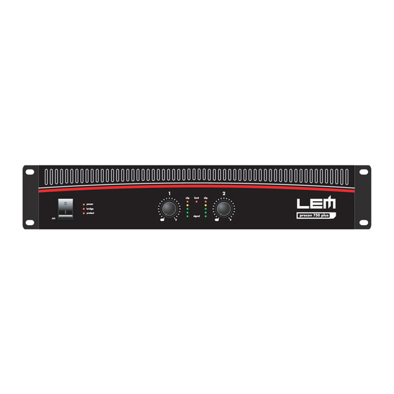
PROCON 750 Test Procedure
3
PROCON 950 Test Procedure
3
PROCON 1100 Test Procedure
4
PROCON 1250 Test Procedure
4
PROCON 1500 Test Procedure
5
PROCON 400 Schematic
6
PROCON 750 Schematic
7
PROCON 950 Schematic
8
PROCON 1100 Schematic
9
PROCON 1250 Schematic
10
PROCON 1500 Schematic
11
Notice
✔
Service must be carried out by qualified personnel only. Any tampering carried out by unqualified personnel during the guarantee period
will forfeit the right to guarantee.
✔
For a correct operation of the instrument, after having switched off, be careful to wait at least 3 seconds before switching on again.
✔
To improve the device's specifications, the schematic diagrams may be subject to change without prior notice.
All components marked by this symbol have special safety characteristics, when replacing any of these components use only
manufacturer's specified parts.
✔
The (µ) micro symbol of capacitance value is substituted by U.
✔
Ω
The (
✔
The electrolytic capacitors are 25Vdc rated voltage unless otherwise specified.
✔
All resistors are 1/8W unless otherwise specified.
✔
All switches shown in the "OFF" position. All DC voltages measured to ground with a voltmeter 20KOhm/V.
✔
Soldering point.
✔
Male connector.
✔
Female connector.
✔
ATTENTION
✒
GENERALMUSIC S.p.A. Sales Division: 47842 S.Giovanni in Marignano (RN) ITALY - Via delle Rose, 12
code 270266
¤
Phone +39(0)541/959511 - Fax +39(0)541/957404 - Internet: www.generalmusic.com
) omega symbol of resistance value is substituted by E.
Supply voltage.
Test point.
Flag joined with one or more flags
M/F faston connector.
with the same signal name inscribed.
Observe precautions when handling electrostatic sensitive devices.
Logic supply ground.
Analog supply ground.
Chassis ground.
Earth ground.
1 1 1 1 1
Advertisement
Table of Contents


Need help?
Do you have a question about the PROCON 400 and is the answer not in the manual?
Questions and answers