
Related Manuals for HP HP Chromebook


Summary of Contents for HP HP Chromebook
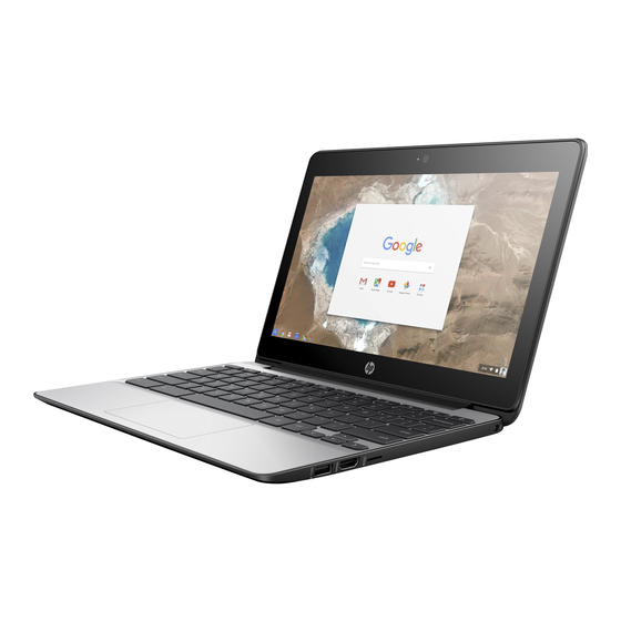
- Page 1 HP Chromebook and HP Chromebook 11 G5 Maintenance and Service Guide IMPORTANT! This document is intended for HP authorized service providers only.
- Page 2 © Copyright 2016 HP Development Company, L.P. Bluetooth is a trademark owned by its proprietor and used by HP Inc. under license. Intel and Celeron are trademarks of Intel Corporation in the U.S. and other countries. SD Logo is a trademark of its proprietor.
- Page 3 Safety warning notice WARNING! To reduce the possibility of heat-related injuries or of overheating the device, do not place the device directly on your lap or obstruct the device air vents. Use the device only on a hard, flat surface. Do not allow another hard surface, such as an adjoining optional printer, or a soft surface, such as pillows or rugs or clothing, to block airflow.
- Page 4 Safety warning notice...
-
Page 5: Table Of Contents
Table of contents 1 Product description ............................1 2 External component identification ........................3 Right side ................................3 Left side ................................. 4 Display ..................................5 Top ..................................6 TouchPad ............................. 6 Button ..............................7 Bottom ................................... 8 Labels ..................................8 3 Illustrated parts catalog .......................... - Page 6 Speakers ............................32 System board ............................ 33 Heat sink ............................35 Display assembly ..........................37 Power connector and cable ....................... 43 6 Specifications .............................. 45 7 Power cord set requirements ........................46 Requirements for all countries ..........................46 Requirements for specific countries and regions ....................47 8 Recycling ..............................
-
Page 7: Product Description
2048 MB (8 GB, 128 M x 32 x 2 x 2 pcs and 4096 MB (8 GB, 128 M x 32 x 2 x 4 pcs Storage Supports 16 GB (32 GB for HP Chromebook 11 G5) embedded MultiMedia Controller (eMMC) Audio and video... - Page 8 Taps enabled as default Power requirements Supports a 2-cell, 43.7 Wh, polymer battery Supports a 65 W HP Smart AC adapter (non-PFC, EM, 4.5 mm) and 45 W HP Smart AC adapter (non-PFC, RC, 4.5 mm) AC adapter Operating system...
-
Page 9: External Component Identification
External component identification Right side Component Description USB 3.0 charging (powered) port Connects an optional USB device, such as a keyboard, mouse, external drive, scanner or USB hub. Standard USB ports will not charge all USB devices or will charge using a low current. -
Page 10: Left Side
Left side Component Description Security cable slot Attaches an optional security cable to the computer. NOTE: The security cable is designed to act as a deterrent, but it may not prevent the computer from being mishandled or stolen. USB 3.0 charging (powered) port Connects an optional USB device, such as a keyboard, mouse, external drive, scanner or USB hub. -
Page 11: Display
Display Component Description WLAN antennas* Send and receive wireless signals to communicate with wireless local area networks (WLANs). NOTE: WLAN antennas are not visible on the exterior of the device. Internal microphones** Record sound. Camera light On: The camera is in use. HD camera Record video and capture still photographs in HD resolution *The antennas and sensors are not visible from the outside of the computer. -
Page 12: Top
TouchPad Component Description TouchPad Reads your finger gestures to move the pointer or activate items on the screen. Chapter 2 External component identification... -
Page 13: Button
Button Component Description Power button ● When the computer is off, press the button to turn on the computer. ● When the computer is in the Sleep state, press the button briefly to exit Sleep. ● When the computer is on and you want to lock the screen, press the button until you see the sign-in screen appear. -
Page 14: Bottom
Bottom Component Description Speakers (2) Produce sound. Labels The labels affixed to the computer provide information you may need when you troubleshoot system problems or travel internationally with the computer. IMPORTANT: All labels described in this section will be affixed to the bottom of the computer. Service label—Provides important information to identify your computer. - Page 15 Component Warranty period Model number (select products only) Component Model name (select products only) Product number Serial number Warranty period ● Regulatory label(s)—Provide(s) regulatory information about the computer. ● Wireless certification label(s)—Provide(s) information about optional wireless devices and the approval markings for the countries or regions in which the devices have been approved for use.
-
Page 16: Illustrated Parts Catalog
Illustrated parts catalog NOTE: HP continually improves and changes product parts. For complete and current information on supported parts for your computer, go to http://partsurfer.hp.com, select your country or region, and then follow the on-screen instructions. Chapter 3 Illustrated parts catalog... -
Page 17: Computer Major Components
Computer major components Computer major components... - Page 18 For display assembly spare part information, see Display assembly subcomponents on page The HP Chromebook 11 G5 model touch displays are only spared as full hinge-ups. Individual components are not spared for these touch screen displays. Keyboard/top cover (includes keyboard cable): NOTE: Keyboard/top cover is spared with the TouchPad under spare part kits with spare part numbers 900818-xxx.
- Page 19 Speaker Kit (includes left and right speakers and cables) 900817-001 (10) Battery: 855701–001 2-cell, 43.7 Wh, long life; includes cable (for use with HP Chromebook 11 G5 models only) 2-cell, 43.7 Wh, 5.68ah LI DRO2043XL-PL includes cable 859357-855 (11) Power connector with cable...
-
Page 20: Display Assembly Subcomponents
11.6 in, high-definition (HD), (1366×768), UWVA, white light-emitting diode (WLED), HU, 901252-001 slim, (3.6 mm); 16:9 aspect ratio; typical brightness: 220 nits, eDP, touch, (for use with HP Chromebook 11 G5 models only) 11.6 in, HD, (1366×768), UWVA, WLED, touch, flat (3.0 mm); 16:9 aspect ratio; typical 906629-001 brightness: 220 nits, eDP, touch solution with Gorilla®... - Page 21 WLAN antenna (includes left and right WLAN cables and transceivers) 900806-001 Display panel cable 900812-001 Display panel cable (touch screen) for use with HP Chromebook models only 906717-001 Display enclosure: (includes rubber padding and shielding) For use with HP Chromebook 11 G5 non-touch screen models only...
-
Page 22: Miscellaneous Parts
Component Spare part number AC adapter: 65 W HP Smart AC adapter (3-pin, PFC, EM, 4.5 mm, DT6U). For use with HP Chromebook 11 G5 models 859925-007 only 45 W HP Smart AC adapter (non-PFC, SB, 4.5 mm, DT). For use with HP Chromebook 11 G5 models only 854844-001 45 W HP Smart AC adapter (non-PFC, SMART RC, 4.5 mm). - Page 23 Component Spare part number 349756-002 Rubber Kit: (includes 2 display bezel screw covers, 4 rubber feet, and 2 rubber screw covers) For use with HP Chromebook 11 G5 models only 901282-001 For use with HP Chromebook models only 900802-001 Screw Kit:...
-
Page 24: Removal And Replacement Preliminary Requirements
Removal and replacement preliminary requirements Tools required You will need the following tools to complete the removal and replacement procedures: ● Flat-bladed screw driver ● Magnetic screw driver Phillips P0 screw driver ● Service considerations The following sections include some of the considerations that you must keep in mind during disassembly and assembly procedures. -
Page 25: Drive Handling
Drive handling CAUTION: Drives are fragile components that must be handled with care. To prevent damage to the computer, damage to a drive, or loss of information, observe these precautions: Before removing or inserting a drive, shut down the computer. If you are unsure whether the computer is off or in Hibernation, turn the computer on, and then shut it down through the operating system. -
Page 26: Grounding Guidelines
Grounding guidelines Electrostatic discharge damage Electronic components are sensitive to electrostatic discharge (ESD). Circuitry design and structure determine the degree of sensitivity. Networks built into many integrated circuits provide some protection, but in many cases, ESD contains enough power to alter device parameters or melt silicon junctions. A discharge of static electricity from a finger or other conductor can destroy static-sensitive devices or microcircuitry. -
Page 27: Packaging And Transporting Guidelines
Packaging and transporting guidelines Follow these grounding guidelines when packaging and transporting equipment: To avoid hand contact, transport products in static-safe tubes, bags, or boxes. ● ● Protect ESD-sensitive parts and assemblies with conductive or approved containers or packaging. Keep ESD-sensitive parts in their containers until the parts arrive at static-free workstations. ●... - Page 28 Equipment guidelines Grounding equipment must include either a wrist strap or a foot strap at a grounded workstation. ● When seated, wear a wrist strap connected to a grounded system. Wrist straps are flexible straps with a minimum of one megohm ±10% resistance in the ground cords. To provide proper ground, wear a strap snugly against the skin at all times.
-
Page 29: Removal And Replacement Procedures
Make special note of each screw size and location during removal and replacement. Computer feet The computer feet are included in the Rubber Kit, available using spare part number 901292-001 for HP Chromebook 11 G5 models and 900802-001 for HP Chromebook models. -
Page 30: Keyboard/Top Cover
Keyboard/top cover spare part kits with spare part numbers 900818-xxx are spared with the TouchPad board. Description Spare part number Description Spare part number For use with HP Chromebook and HP Chromebook 11 G5 models For use in Belgium 900818-A41 For use in the Netherlands 900818-B31 For use in Canada... - Page 31 Remove the eleven Phillips PM1.9×6.7 screws (2) that secure the keyboard/top cover to the base enclosure. Turn the computer right side up with the front toward you. Open the computer as far as it will open. Use a prying tool to disengage the top cover and base plastic. Start from the rear (1) of the keyboard/top cover until it separates from the back edge of the base enclosure.
- Page 32 Lift the front of the keyboard/top cover to access the TouchPad and keyboard cables (1). Disconnect the TouchPad cable from the connector (2) on the system board. Disconnect the keyboard cable (3) from the system board. Remove the keyboard/top cover. NOTE: The thermal material must be thoroughly cleaned from the surfaces of the heat sink and the system board components each time the keyboard/top cover is removed.
-
Page 33: Wlan Module
WLAN module Description Spare part number Intel Dual Band Wireless-AC 7265 802.11 ac 2×2 WiFi + Bluetooth 4.0 Combo Adapter (for use with HP 901229-001 Chromebook models only) Intel Dual Band Wireless-N 7260AN 802.11 a/b/g/n 2×2 WiFi + Bluetooth 4.0 Combo Adapter (for use... -
Page 34: Hall Sensor Board
Remove the WLAN module (3) by pulling the module away from the slot at an angle. NOTE: If the WLAN antenna is not connected to the terminal on the WLAN module, a protective sleeve must be installed on the antenna connector, as shown in the following illustration. Reverse this procedure to install the WLAN module. -
Page 35: Connector Board And Cable
Before removing the Hall sensor board, follow these steps: Shut down the computer. If you are unsure whether the computer is off or in Hibernation, turn the computer on, and then shut it down through the operating system. Disconnect all external devices connected to the computer. Disconnect the power from the computer by first unplugging the power cord from the AC outlet and then unplugging the AC adapter from the computer. -
Page 36: Battery
Battery Description Spare part number Battery (2-cell, 43 Wh, 3.25 AHr, Li-ion, LongLife-PL; includes cable) for use with HP Chromebook 11 G5 855710-001 models only Battery (2-cell, 43 Wh, 5.68 AHr, Li-ion, DRO2043XL-PL, non-touch; includes cable) For use with HP... - Page 37 Remove the keyboard/top cover (see Keyboard/top cover on page 24). Remove the WLAN module (see WLAN module on page 27). Remove the Hall sensor board (see Hall sensor board on page 28). Remove the connector board and cable (see Connector board and cable on page 29).
-
Page 38: Speakers
Speakers Description Spare part number Speaker Kit (includes left and right speakers and cables) 900817-001 Before removing the speakers, follow these steps: Turn off the computer. If you are unsure whether the computer is off or in Hibernation, turn the computer on, and then shut it down through the operating system. Disconnect the power from the computer by unplugging the power cord from the computer. -
Page 39: System Board
Intel Celeron N2840 2.16 GHz, 4.0 GB of system memory and 32 GB of eMMC system storage (for use 901250-001 with HP Chromebook 11 G5 models only) Before removing the system board, follow these steps: Turn off the computer. If you are unsure whether the computer is off or in Hibernation, turn the computer on, and then shut it down through the operating system. - Page 40 Disconnect the power connector cable (3) from the system board. Remove the four Phillips screws (1) that secure the system board to the base enclosure. Remove the system board (2). Reverse this procedure to install the system board. Chapter 5 Removal and replacement procedures...
-
Page 41: Heat Sink
Heat sink Description Spare part number Heat sink (includes replacement thermal material) 900040-001 Before removing the heat sink, follow these steps: Turn off the computer. If you are unsure whether the computer is off or in Hibernation, turn the computer on, and then shut it down through the operating system. Disconnect the power from the computer by unplugging the power cord from the computer. - Page 42 Reverse this procedure to install the heat sink. Chapter 5 Removal and replacement procedures...
-
Page 43: Display Assembly
Display assembly NOTE: The HP Chromebook 11 G5 model touch displays, spare part number 901252-001, are only spared as full hinge-ups. Before removing the display assembly, follow these steps: Turn off the computer. If you are unsure whether the computer is off or in Hibernation, turn the computer on, and then shut it down through the operating system. - Page 44 Remove the display bezel (4). The display bezel is available using spare part number 902764-001 for the HP Chromebook 11 G5 models and 900799-001 for the HP Chromebook models.
- Page 45 Detach the camera/microphone module (1) from the display enclosure. (The camera/microphone module is attached to the display enclosure with double-sided adhesive at two locations.) Disconnect the camera/microphone module cable (2) from the camera/microphone module. Remove the camera/microphone module (3). Remove the camera/microphone module. The camera/microphone module is available using spare part number 756761-037.
- Page 46 Lift the top edge of the display panel (2) and swing it up and forward until it rests upside down in front of the display enclosure. Disconnect the display panel cable (2) from the display panel (3). Remove the display panel. The display panel is available using spare part numbers 762229-007 (11.6 in, HD, AntiGlare, (1366×768), SVA, LED, flat [3.0 mm]), 901252-001 (11.6 in, HD, (1366×768), UWVA, LCD, Touch [3.6 mm], and 90662-001, 11.6 in, HD, (1366×768), SVA, WLED, touch, flat (3.0 mm).
- Page 47 Remove the display panel cable (2). The display panel cable is available using spare part number 900812-001. If it is necessary to replace the display hinges: Remove the four Phillips broad head screws (1) and the four Phillips screws (2) that secure the display hinges to the display enclosure.
- Page 48 If it is necessary to replace the WLAN antenna cables and transceivers: Detach the WLAN antenna transceivers (1) from the display enclosure. (The WLAN antenna transceivers are attached to the display enclosure with double-sided adhesive.) Release the grounding tape (2) that secures the wireless antenna cable to the display enclosure near the right hinge.
-
Page 49: Power Connector And Cable
Power connector and cable Description Spare part number Power connector and cable 808155-013 Before removing the power connector cable, follow these steps: Shut down the computer. If you are unsure whether the computer is off or in Hibernation, turn the computer on, and then shut it down through the operating system. Disconnect all external devices connected to the computer. - Page 50 Reverse this procedure to install the power connector cable. Chapter 5 Removal and replacement procedures...
-
Page 51: Specifications
Specifications Metric U.S. Computer dimensions Width 20.5 cm 8.07 in Depth 28.6 cm 11.25 in Height 1.82 cm 0.72 in Weight 1.2 kg 2.63 lbs Temperature Operating 5°C to 35°C 41°F to 95°F ‑20°C to 60°C ‑4°F to 140°F Nonoperating Relative humidity (noncondensing) Operating 10% to 90%... -
Page 52: Power Cord Set Requirements
Power cord set requirements The wide-range input feature of the computer permits it to operate from any line voltage from 100 to 120 V ac, or from 220 to 240 V ac. The 3-conductor power cord set included with the computer meets the requirements for use in the country or region where the equipment is purchased. -
Page 53: Requirements For Specific Countries And Regions
Requirements for specific countries and regions Country/region Accredited agency Applicable note number Argentina IRAM Australia Austria Belgium CEBEC Brazil ABNT Canada Chile Denmark DEMKO Finland FIMKO France Germany India Israel Italy Japan The Netherlands KEMA New Zealand SANZ Norway NEMKO The People's Republic of China Saudi Arabia SASO... - Page 54 Country/region Accredited agency Applicable note number The appliance coupler, flexible cord, and wall plug must bear a “T” mark and registration number in accordance with the Japanese Dentori Law. The flexible cord must be Type VCR, 3-conductor, 0.75 mm² or 1.25 mm² conductor size. The wall plug must be a two-pole grounding type with a Japanese Industrial Standard c/o (7 A, 125 V ac) configuration.
-
Page 55: Recycling
Follow the local laws and regulations in your area for battery disposal. HP encourages customers to recycle used electronic hardware, HP original print cartridges, and rechargeable batteries. For more information about recycling programs, see the HP Web site at http://www.hp.com/recycle. -
Page 56: Index
Index right side 3 guidelines ac adapter dongle, spare part top 6 equipment 22 number 16 computer major components 11 grounding 20 AC adapter light connector board packaging 21 identifying 3, 4 spare part numbers 13 transporting 21 AC adapter, spare part numbers 16 connector, power 3 workstation 21 antenna... - Page 57 lights 4 sensors 1 AC adapter 3 serviceability 2 USB 3.0 charging (powered) port, webcam 5 storage 1 identifying 3, 4 video 1 wireless 1 memory, product description 1 video, product description 1 product name 1 microphone product name and number, product description 1 computer 8 webcam light, identifying 5...
Need help?
Do you have a question about the HP Chromebook and is the answer not in the manual?
Questions and answers