Table of Contents
Advertisement
Quick Links
CONTENTS
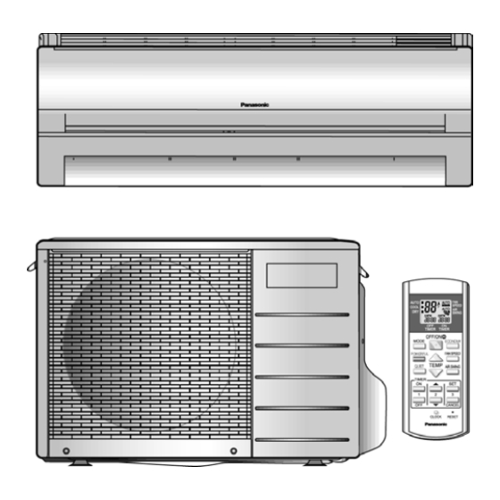
CS-C9DKU CU-C9DKU
CS-C12DKU CU-C12DKU
Page
2
3
6
6
8
10
10
11
12
13
14
15
15
16
17
18
© 2005 Panasonic HA Air-Conditioning (M) Sdn Bhd
(11969-T). All rights reserved. Unauthorized copying
and distribution is a violation of law.
Order No. MAC0502033C1
Air Conditioner
Page
21
23
23
24
24
25
26
26
26
27
28
34
34
36
36
36
Advertisement
Table of Contents

Related Manuals for Panasonic CS-C12DKU


Summary of Contents for Panasonic CS-C12DKU
-
Page 1: Table Of Contents
10.1. Safety Precautions 10.2. Attached accessories 10.3. Select the best location 10.4. Indoor/Outdoor Unit Installation Diagram © 2005 Panasonic HA Air-Conditioning (M) Sdn Bhd (11969-T). All rights reserved. Unauthorized copying and distribution is a violation of law. Order No. MAC0502033C1... -
Page 2: Features
CS-C9DKU CU-C9DKU / CS-C12DKU CU-C12DKU 10.5. Indoor unit 10.6. Outdoor unit 11 2-way, 3-way Valve 11.1. Evacuation of Installation 11.2. Pumping down 11.3. Evacuation of Re-installation 11.4. Balance refrigerant of the 2-way, 3-way valves 11.5. Evacuation 11.6. Gas charging 12 Servicing Information 12.1. -
Page 3: Functions
CS-C9DKU CU-C9DKU / CS-C12DKU CU-C12DKU 2 Functions ı... - Page 4 CS-C9DKU CU-C9DKU / CS-C12DKU CU-C12DKU...
- Page 5 CS-C9DKU CU-C9DKU / CS-C12DKU CU-C12DKU...
-
Page 6: Product Specifications
CS-C9DKU CU-C9DKU / CS-C12DKU CU-C12DKU 3 Product Specifications 3.1. CS-C9DKU CU-C9DKU Power Source (Phase, Voltage, Cycle) Cooling Capacity Moisture Removal Airflow Method Air Volume Noise Level Electrical Data Input Power Running Current Starting Current Piping Connection Port (Flare piping) Pipe Size... - Page 7 — inch (mm) — P.P. Honeycomb µF, VAC — µF, VAC 5.0 µF, 230VAC CS-C9DKU CU-C9DKU / CS-C12DKU CU-C12DKU Outdoor unit — 2 Stage Overload Protector 26-18/32 (675) 13.0 20/32 (1.6) — Capillary Tube 35 µF, 370VAC 8.0 µF, 230VAC...
-
Page 8: Cs-C12Dku Cu-C12Dku
CS-C9DKU CU-C9DKU / CS-C12DKU CU-C12DKU 3.2. CS-C12DKU CU-C12DKU Power Source (Phase, Voltage, Cycle) Cooling Capacity Moisture Removal Airflow Method Air Volume Noise Level Electrical Data Input Power Running Current Starting Current Piping Connection Port (Flare piping) Pipe Size (Flare piping) - Page 9 Indoor unit inch (mm) — l/min — inch (mm) — P.P. Honeycomb µF, VAC — µF, VAC 5.0 µF, 230VAC CS-C9DKU CU-C9DKU / CS-C12DKU CU-C12DKU Outdoor unit 16-23/32 (425) 18.0 2/32 (1.7) — Capillary Tube 50 µF, 370VAC 8.0 µF, 230VAC...
-
Page 10: Dimensions
CS-C9DKU CU-C9DKU / CS-C12DKU CU-C12DKU 4 Dimensions 4.1. Indoor Unit & Remote Control... -
Page 11: Outdoor Unit
CS-C9DKU CU-C9DKU / CS-C12DKU CU-C12DKU 4.2. Outdoor Unit CU-C9DKU CU-C12DKU... -
Page 12: Refrigeration Cycle Diagram
CS-C9DKU CU-C9DKU / CS-C12DKU CU-C12DKU 5 Refrigeration Cycle Diagram CS-C9DKU CU-C9DKU CS-C12DKU CU-C12DKU... -
Page 13: Block Diagram
CS-C9DKU CU-C9DKU / CS-C12DKU CU-C12DKU 6 Block Diagram CS-C9DKU CU-C9DKU CS-C12DKU CU-C12DKU... -
Page 14: Wiring Diagram
CS-C9DKU CU-C9DKU / CS-C12DKU CU-C12DKU 7 Wiring Diagram CS-C9DKU CU-C9DKU CS-C12DKU CU-C12DKU REMARKS : BLUE : BROWN : BLACK : GRAY : ORANGE : PINK : RED : WHITE : YELLOW/GREEN Power Supply Cord Resistance of Indoor Fan Motor Windings... -
Page 15: Operation Details
The remote control setting temperature, which takes the reading of intake air temperature sensor, can be adjusted from 60.8°F to 86°F. During cooling operation, the compressor will stop running and restart as shown in below figure. 8.1.1. Cooling Operation Time Diagram CS-C9DKU CU-C9DKU / CS-C12DKU CU-C12DKU... -
Page 16: Soft Dry Operation
CS-C9DKU CU-C9DKU / CS-C12DKU CU-C12DKU 8.2. Soft Dry Operation Soft Dry operation can be set using remote control. Soft Dry operation is applied to dehumidify and to perform a gentle cooling to the room. This operation starts when the intake air temperature sensor reaches the setting temperature on the remote control. -
Page 17: Automatic Operation
CS-C9DKU CU-C9DKU / CS-C12DKU CU-C12DKU 8.3. Automatic Operation Automatic operation can be set using remote control. This operation starts to operate with indoor fan at SLo speed for 20 seconds to judge the intake air temperature. After judged the temperature, the operation mode is determined by referring to the below standard. -
Page 18: Operation Control
60 Seconds Forced Operation Once the air conditioner is turned on, the compressor will not stop within 60 seconds in a normal operation although the intake air temperature has reached the thermo-off temperature. However, force stop by pressing the OFF/ON operation button at the remote control is permitted. -
Page 19: Compressor Reverse Rotation Protection Control
- Indoor intake temperature is more than 75.2°F and less than 86°F. - Remote Control setting temperature is less than 77°F - Compressor is on. - Cooling Operation Mode. - Indoor fan motor operate at Low fan speed or QLo. CS-C9DKU CU-C9DKU / CS-C12DKU CU-C12DKU... - Page 20 CS-C9DKU CU-C9DKU / CS-C12DKU CU-C12DKU Anti-Dew Formation is control by:- Increasing Air Flow Volume 1. Lo fan speed. Lo fan speed is changed to Lo+ after 30 min to prevent dew formation. 2. QLo fan speed. Dew formation may occur at QLo cool, therefore QLo cool is operated only 1hr 30min (1 hr QLo, 30 min QLo + 80 rpm). After that, it operates at QLo + 160 rpm (However Quiet LED remains on).
-
Page 21: Indoor Fan Speed Control
Fan Speed Rotation Chart Speed S Hi H Lo C Lo S Lo SS Lo Q S Hi Q Hi Q Me QH Lo Q Lo Fan Speed (rpm) CS-C9DKU CS-C12DKU 1250 1310 1160 1280 1080 1060 1180 CS-C9DKU CU-C9DKU / CS-C12DKU CU-C12DKU... - Page 22 CS-C9DKU CU-C9DKU / CS-C12DKU CU-C12DKU 8.5.2. Automatic Fan Speed Control When set to Auto Fan Speed, the fan speed is adjusted between maximum and minimum setting as shown in the table. Fan speed rotates in the range of Hi and Me.
-
Page 23: Outdoor Fan Speed Control
There is only one speed for outdoor fan motor. When the air conditioner is turned on, the compressor and the outdoor fan will operate simultaneously. Likewise, both compressor and outdoor fan will stop at the same time if the unit is turned off. -
Page 24: Horizontal Airflow Direction Control
CS-C9DKU CU-C9DKU / CS-C12DKU CU-C12DKU 8.8. Horizontal Airflow Direction Control The horizontal airflow direction louvers can be adjusted manually by hand. 8.9. Powerful Operation The Powerful operation is to achieve the setting temperature quickly. When Powerful operation is set, the setting temperature will be automatically decreased 5.4°F internally against the present setting temperature (Lower temperature limit: 60.8°F). -
Page 25: Quiet Operation
RPM control during Hi cool Auto Airflow Direction:- Quiet operation stops when:- Quiet button is pressed again. Stopped by OFF/ON operation button. Timer OFF activates. Powerful button is pressed. Economy button is pressed. Operation mode button is changed. CS-C9DKU CU-C9DKU / CS-C12DKU CU-C12DKU... -
Page 26: Timer Control
It will start with previous operation mode and airflow direction. If there are more than one air conditioner unit in operation and power failure occur, restart time for each unit to operate will be decided randomly using 4 parameters:- intake air temperature, setting temperature, fan speed and air swing louver position. -
Page 27: Economy Mode Operation
8.14. Economy Mode Operation Purpose of this operation is to save or reduced electrical power consumption of the room air conditioner. However consumer is advised to use Economy Mode operation after the room temperature reaches the desired temperature. 1. Cooling and Soft Dry Mode When the Economy Mode is set, the set temperature will be automatically increased 0.9°F against the present setting... -
Page 28: Operating Instructions
CS-C9DKU CU-C9DKU / CS-C12DKU CU-C12DKU 9 Operating Instructions... - Page 29 CS-C9DKU CU-C9DKU / CS-C12DKU CU-C12DKU...
- Page 30 CS-C9DKU CU-C9DKU / CS-C12DKU CU-C12DKU...
- Page 31 CS-C9DKU CU-C9DKU / CS-C12DKU CU-C12DKU...
- Page 32 CS-C9DKU CU-C9DKU / CS-C12DKU CU-C12DKU...
- Page 33 CS-C9DKU CU-C9DKU / CS-C12DKU CU-C12DKU...
-
Page 34: Installation Instructions
CS-C9DKU CU-C9DKU / CS-C12DKU CU-C12DKU 10 Installation Instructions 1. Philips screw driver 2. Level gauge 3. Electric drill, hole core drill (ø2 3/4”) 4. Hexagonal wrench (5/32”) 10.1. Safety Precautions Read the following “SAFETY PRECAUTIONS” carefully before installation. Electrical work must be installed by a licensed electrician. - Page 35 Select an installation location which is rigid and strong enough to support or hold the unit, and select a location for easy maintenance. 2. Power supply connection to the room air conditioner. Connect the power supply of the room air conditioner to the mains. Power supply point should be in easily accessible place for the power disconnection in case of emergency.
-
Page 36: Attached Accessories
CS-C9DKU CU-C9DKU / CS-C12DKU CU-C12DKU 10.2. Attached accessories Applicable piping kit CZ-3F5, 7AEN (C9DK) CZ-4F5,7, 10AN (C12DK) 10.3. Select the best location INDOOR UNIT There should not be any heat source or steam near the unit. There should not be any obstacles blocking the air circulation. -
Page 37: Indoor Unit
Drill the piping hole at either the right or the left and the hole should be slightly slanted to the outdoor side. CS-C9DKU CU-C9DKU / CS-C12DKU CU-C12DKU 10.5.3. TO DRILL A HOLE IN THE WALL AND INSTALL A SLEEVE OF PIPING 1. -
Page 38: Indoor Unit Installation
CS-C9DKU CU-C9DKU / CS-C12DKU CU-C12DKU 10.5.4. INDOOR UNIT INSTALLATION 1. For the right rear piping 2. For the embedded piping (This can be used for left rear piping & left bottom piping also.) - Page 39 10.5.5. INDOOR UNIT ELECTRICAL WIRING 1. Remove the control board metal cover. CS-C9DKU CU-C9DKU / CS-C12DKU CU-C12DKU 2. Unscrew the conduit cover & fix the conduit connector to conduit cover with lock nut, then secure it against chassis. 3. Connecting wire between indoor unit and outdoor unit should bw UL listed or CSA approved 4 x AWG16 wire.
-
Page 40: Outdoor Unit
CS-C9DKU CU-C9DKU / CS-C12DKU CU-C12DKU HOW TO TAKE OUT FRONT GRILLE Please follow the steps below to take out front grille if necessary such as when servicing. 1. Open the intake grille and remove the screw at the front of the front grille. -
Page 41: Connecting The Piping
Turn the piping end down to avoid the metal powder entering the pipe. 3. Please make flare after inserting the flare nut onto the copper pipes. Liquid 1/4” (13.3 lbf.ft) 1/4” (13.3 lbf.ft) CS-C9DKU CU-C9DKU / CS-C12DKU CU-C12DKU... -
Page 42: Evacuation Of The Equipment
CS-C9DKU CU-C9DKU / CS-C12DKU CU-C12DKU 10.6.4. EVACUATION OF THE EQUIPMENT WHEN INSTALLING AN AIR CONDITIONER, BE SURE TO EVACUATE THE AIR INSIDE THE INDOOR UNIT AND PIPES in the following procedure. 1. Connect a charging hose with a push pin to the Low side of a charging set and the service port of the 3-way valve. -
Page 43: Pipe Insulation
Measure the temperature of the intake and discharge air. Ensure the difference between the intake temperature and the discharge is more than 14.4°F. CS-C9DKU CU-C9DKU / CS-C12DKU CU-C12DKU 4. Fix the conduit connectors to the conduit holes with lock- nuts, then secure them against the side panel. - Page 44 CS-C9DKU CU-C9DKU / CS-C12DKU CU-C12DKU CHECK ITEMS Is there any gas leakage at flare nut connections? Has the heat insulation been carried out at flare nut connection? Is the connecting wiring being fixed to terminal board firmly? Is the connecting wiring being clamped firmly? Is the drainage OK? (Refer to “Check the drainage”...
-
Page 45: 11 2-Way, 3-Way Valve
Close (With valve cap) Close (Counter-Clockwise) Open (With valve cap) Close (Clockwise) Open Open Open Open CS-C9DKU CU-C9DKU / CS-C12DKU CU-C12DKU 3-way Valve (Gas Side) Shaft Position Service Port Close Close (With valve cap) (With cap) Close Open (Clockwise) (Push-pin) -
Page 46: Evacuation Of Installation
CS-C9DKU CU-C9DKU / CS-C12DKU CU-C12DKU 11.1. Evacuation of Installation WHEN INSTALLING AN AIR CONDITIONER, BE SURE TO EVACUATE THE AIR INSIDE THE INDOOR UNIT AND PIPES in the following procedure. Procedure: 1. Connect a charging hose with a push pin to the Low side of a charging set and the service port of a 3-way valve. -
Page 47: Pumping Down
5. Set the 2-way valve to the closed position. CS-C9DKU CU-C9DKU / CS-C12DKU CU-C12DKU 6. Operate the air conditioner at the cooling cycle and stop it when the gauge indicates 0 PSI (0 kg/cm... -
Page 48: Evacuation Of Re-Installation
CS-C9DKU CU-C9DKU / CS-C12DKU CU-C12DKU 11.3. Evacuation of Re-installation WHEN REINSTALLING AN AIR CONDITIONER, BE SURE TO EVACUATE THE AIR INSIDE THE INDOOR UNIT AND PIPES in the following procedure. Procedure: 1. Connect a charging hose with a push pin to the Low side of a charging set and the service port of the 3-way valve. -
Page 49: Balance Refrigerant Of The 2-Way, 3-Way Valves
PSI (0.5 kg/cm G) to 14.5 PSI (1 kg/cm If there is no air in the refrigeration cycle (the pressure when the air conditioner is not running is higher than 0.1 PSI (1 kg/cm G), discharge the refrigerant until the gauge indicates 7.25 PSI (0.5 km/cm... -
Page 50: Evacuation
CS-C9DKU CU-C9DKU / CS-C12DKU CU-C12DKU 11.5. Evacuation (No refrigerant in the refrigeration cycle) Procedure: 1. Connect the vacuum pump to the charge set’s centre hose. 2. Evacuation for approximately one hour. Confirm that the gauge needle has moved toward -14.5 PSI (-76 cmHg) [vacuum of 4 mmHg or less.]... -
Page 51: Gas Charging
1 minute and then repeat the procedure. (pumping down-pin) CS-C9DKU CU-C9DKU / CS-C12DKU CU-C12DKU This is different from previous procedures. Because you are charging with liquid refrigerant from the gas side, absolutely do no attempt to charge with large amount of liquid refrigerant while operating the air conditioner. -
Page 52: Servicing Information
CS-C9DKU CU-C9DKU / CS-C12DKU CU-C12DKU 12 Servicing Information 12.1. Distinction of Lead Free (PbF) Printed Circuit Board Printed circuit boards (manufactured) using lead free solder will have a PbF stamp on the Printed Circuit board. CAUTION Pb free solder has a higher melting point than standard solder; typically the melting point is 50 - 70°F (30 - 40°C) higher. - Page 53 Release CN-FB connector (Fig.5) Release CN-TH connector (Fig.5) Release CN-STM1 connector (Fig.5) Release CN-DISP connector (Fig.5) CS-C9DKU CU-C9DKU / CS-C12DKU CU-C12DKU Fig. 6 Press the hook to the right then take out the PCB (Fig.6) Remove Ry-Pwr connector (black and brown) from the terminal board.
-
Page 54: Indoor Fan Motor And Cross Flow Fan Removal Procedures
CS-C9DKU CU-C9DKU / CS-C12DKU CU-C12DKU 12.3. Indoor Fan Motor and Cross Flow Fan Removal Procedures Remove Control Board cover Fig. 7 Remove the screw on the left side of the unit. (Fig.7) Pull the hook to the left and lift up the evaporator. (Fig. -
Page 55: Auto Off/On Button
12.4. Auto OFF/ON Button The “Auto OFF/ON Button” (behind the front grille) is used to operate the air conditioner if remote control is misplaced or mulfunctioning. Forced cooling operation is possible by pressing the “Auto OFF/ON Button” for more than 5s where “beep” sound is heard then release the button. -
Page 56: Remote Control Reset
CS-C9DKU CU-C9DKU / CS-C12DKU CU-C12DKU 12.5. Remote Control Reset When the batteries are inserted for the first time or the batteries are replaced, you may notice the indications at remote control’s display screen blink continuously and not functionable. If this condition happens, try to reset the remote control by pushing the reset terminal with a pointing device. -
Page 57: Troubleshooting Guide
CS-C9DKU CU-C9DKU / CS-C12DKU CU-C12DKU 13 Troubleshooting Guide 13.1. Refrigeration cycle system In order to diagnose malfunctions, make sure that there is no electrical problem before inspecting the refrigeration cycle. Such problems include insufficient insulation, problem with the power source, malfunction of compressor or fan motor. -
Page 58: Relationship Between The Condition Of The Air Conditioner And Pressure And Electric Current
CS-C9DKU CU-C9DKU / CS-C12DKU CU-C12DKU 13.2. Relationship between the condition of the air conditioner and pressure and electric current Condition of the air conditioner Insufficient refrigerant (gas leakage) Clogged capillary tube or Strainer Short circuit in the indoor unit Heat radiation deficiency of... -
Page 59: Technical Data
CS-C9DKU CU-C9DKU / CS-C12DKU CU-C12DKU 14 Technical Data 14.1. Thermostat characteristics... -
Page 60: Operation Characteristics
CS-C9DKU CU-C9DKU / CS-C12DKU CU-C12DKU 14.2. Operation characteristics 14.2.1. CS-C9DK CU-C9DK... - Page 61 CS-C9DKU CU-C9DKU / CS-C12DKU CU-C12DKU...
- Page 62 CS-C9DKU CU-C9DKU / CS-C12DKU CU-C12DKU 14.2.2. CS-C12DK CU-C12DK...
- Page 63 CS-C9DKU CU-C9DKU / CS-C12DKU CU-C12DKU...
-
Page 64: Exploded View (Indoor Unit)
CS-C9DKU CU-C9DKU / CS-C12DKU CU-C12DKU 15 Exploded View (Indoor Unit) Note: The above exploded view is for the purpose of parts disassembly and replacement. The non-numbered parts are not kept as standard service parts. -
Page 65: Replacement Parts List (Indoor Unit)
16 Replacement Parts List (Indoor Unit) <Model: CS-C9DKU / CS-C12DKU > REF. NO. PART NAME & DESCRIPTION CHASSY COMPLETE FAN MOTOR, AC15W SINGLE CROSS FLOW FAN COMPLETE BEARING ASS’Y SCREW - CROSS FLOW FAN EVAPORATOR FLARE NUT FLARE NUT INTAKE AIR SENSOR HOLDER... -
Page 66: Exploded View (Outdoor Unit)
CS-C9DKU CU-C9DKU / CS-C12DKU CU-C12DKU 17 Exploded View (Outdoor Unit) CU-C9DK CU-C12DK Note: The above exploded view is for the purpose of parts disassembly and replacement. The non-numbered parts are not kept as standard service parts. -
Page 67: Replacement Parts List (Outdoor Unit)
CWH171011 CWH7080300 CWH151022A CWH102186 CWA28K1123 K6A1ALA00001 XS371356FP-C (35µF, 370VAC) CWH30057 JS231805SPQH CWE041044A CWE041043A CWE06K1036 CWD04C1010 CWE031018A CWH131088 CWH13C1065 CWE161010 CWF564722 CWF612765 CS-C9DKU CU-C9DKU / CS-C12DKU CU-C12DKU CU-C12DKU REMARKS 2P19S126C1A CWB32C1267 CWB15K1151 CWB011148 CWA67C4719 CWH151023A XS371506FP-B (50µF, 370VAC) CWH30060 CWE041073A CWD04C1012... -
Page 68: Electronic Circuit Diagram
CS-C9DKU CU-C9DKU / CS-C12DKU CU-C12DKU 19 Electronic Circuit Diagram 19.1. Indoor Unit SCHEMATIC DIAGRAM 1/4 DISPLAY COMPLETE TIMER/AIR SW(ORG) POWER(GRN) POWERFUL(ORG) QUIET(ORG) ECONOMY(GRN) ELECTRONIC CONTROL UNIT Auto SW01 R1 1 CN-SONIC IC401 R401 C401 6.3V CN-DISP D404 D402 D403 D405... - Page 69 R2 4 R2 5 RY-PWR DRIVE SIGNAL DISPLAY R06 24 k Vss0 VDD0 AUTO RESTART 8 16 R0 9 IC06 B1HBGGF00013 CS-C9DKU CU-C9DKU / CS-C12DKU CU-C12DKU 1000p R1 0 STEPPING AUTO OPERATION MOTOR TEST RUN DRIVE REMOTE CONTROL SIGNAL SOUND INTP2...
- Page 70 CS-C9DKU CU-C9DKU / CS-C12DKU CU-C12DKU SCHEMATIC DIAGRAM 3/4 C143XKTX 4.7k ZNR01 SSR01 C143XKTX 4.7k R4 1 0.01 150k 4.096 MHz (47pF X 2) 100k 0.01 0.01 TEST 10 k R4 8 IC04 IC03 REGULATOR REGULATOR DB01 3300 1.3k R2 9 1.6k...
- Page 71 SCHEMATIC DIAGRAM 4/4 C9DKU/C12DKU POWER SUPPLY SOURCE OUTDOOR UNIT OUTDOOR UNIT TERMINAL FAN MOTOR CAPACITOR COMPRESSOR CAPACITOR MAGNETIC RELAY OVERLOAD PROTECTOR CS-C9DKU CU-C9DKU / CS-C12DKU CU-C12DKU...
- Page 72 CS-C9DKU CU-C9DKU / CS-C12DKU CU-C12DKU...
- Page 73 5 min. 30 sec. 2 min. 0 sec. 1.6 sec. 0 sec. 15 min. 15 sec. 0 ~ 62 sec. 0 ~ 6.2 sec. CS-C9DKU CU-C9DKU / CS-C12DKU CU-C12DKU Remarks Soft Dry: 10 min. operation Comp. ON 5 min. and above...
-
Page 74: Remote Control
CS-C9DKU CU-C9DKU / CS-C12DKU CU-C12DKU 19.2. Remote Control... -
Page 75: Print Pattern Indoor Unit Printed Circuit Board
CS-C9DKU CU-C9DKU / CS-C12DKU CU-C12DKU 19.3. Print Pattern Indoor Unit Printed Circuit Board... - Page 76 CS-C9DKU CU-C9DKU / CS-C12DKU CU-C12DKU...
- Page 77 CS-C9DKU CU-C9DKU / CS-C12DKU CU-C12DKU Indicator Printed Circuit Board [PHAAM] Printed in Malaysia...