Siemens EcoView Installation Instructions Manual
Hide thumbs
Also See for EcoView:
- Installation instructions manual (8 pages) ,
- Installation instructions manual (9 pages) ,
- Owner's manual (62 pages)
Advertisement
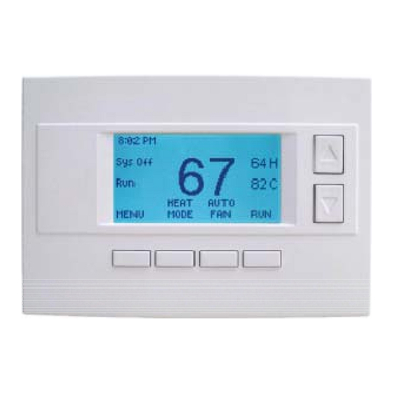
EcoView™ Thermostat
Product Description
This document covers the installation and
commissioning of the EcoView™ thermostat and
sensors components the EcoView system.
See the following documents for installation of other
EcoView system components:
•
EcoView™ 8 DO Module Installation and
Commissioning (129-565)
•
EcoView™Multi-phase Meter Installation
Instructions (129-563)
•
EcoView™ Touchscreen Installation and
Commissioning (129-562)
Product Number
97-001 EcoView Thermostat
Caution Notations
CAUTION:
Required Tools
•
Screwdriver
•
Electric drill
Expected Installation Time
15 minutes
CAUTION:
If thermostat security enclosures are
required, they must be non-metallic so they
will not interfere with the radio transmission.
Prerequisites
•
Power off the AC unit before attempting
removal of the existing thermostat.
•
Thermostat wires are typically color coded. If
not, you must make note of which terminal
designator each wire was attached to.
Item Number 129-566, Rev. BA
Equipment damage or loss of
data may occur if you do not
follow the procedures as
specified.
Installation Instructions
•
This thermostat is a direct replacement and
should accept the same wires. However, if
the AC unit is configured as a heat pump,
there are settings that can be adjusted in the
configuration menu on the thermostat.
•
Remove the existing thermostat before
proceeding.
•
Ensure that there is 24 Vac present at the
COM and RH terminals. If it is not present,
ensure that it is run from the HVAC unit.
COM is typically the blue wire, although on
some thermostats it can be a black wire.
Installation
1.
Remove the base plate from the thermostat
housing by pulling straight up.
2.
Install the thermostat base plate.
a. Feed the existing wires through the opening
in the base plate.
b. Secure the base plate to the mounting
surface using appropriate hardware.
Figure 1. Thermostat Base Plate.
NOTE:
If 24 Vac was present at the
thermostat, skip Step 3 and proceed
to Step 4.
Document No. 129-566
December 19, 2011
Page 1 of 7
Advertisement
Table of Contents

Related Manuals for Siemens EcoView


Summary of Contents for Siemens EcoView
-
Page 1: Product Description
AC unit is configured as a heat pump, This document covers the installation and there are settings that can be adjusted in the commissioning of the EcoView™ thermostat and configuration menu on the thermostat. sensors components the EcoView system. -
Page 2: Remote Sensors
The remote sensor (see Figure 3) has two Press Done twice to return to the main menu. wires. These wires are not polarized, and may Use the down arrow to scroll down to ZigBee need to be interchanged. install. Page 2 of 7 Siemens Industry, Inc. -
Page 3: Refrigeration Sensors
(see Figure 1). Leave the other Belden DFLEX3, and attach the end of the shield unattached. shield to 24C on the thermostat base plate (see Figure 1). Leave the other end of the shield unattached. Siemens Industry, Inc. Page 3 of 7... -
Page 4: Wiring Diagrams
• If you have a single-stage heating system, leave this No setup is required for this configuration. set to N. • If you have a 2-stage heating system, set to Y to enable. Page 4 of 7 Siemens Industry, Inc. - Page 5 If you get cooling when you expect heating, For changeover with cool systems (Orange wire, O change the changeover type to the opposite terminal): set C/O type to w/cool (most common and setting. default setting). Siemens Industry, Inc. Page 5 of 7...
-
Page 6: Fcc And Ic Interference Requirements
ICES-003 à l'issue canadienne 4 (le février 2004). » conjunction with any other antenna or transmitter.” (For compliance with FCC Code of Federal Regulations Title 47 Part 2.1093) Page 6 of 7 Siemens Industry, Inc. - Page 7 Information in this publication is based on current specifications. The company reserves the right to make changes in specifications and models as design improvements are introduced. EcoView is a trademark of Siemens Industry, Inc. Other product or company names mentioned herein may be the trademarks of their respective owners. © 2011 Siemens Industry, Inc.
Need help?
Do you have a question about the EcoView and is the answer not in the manual?
Questions and answers