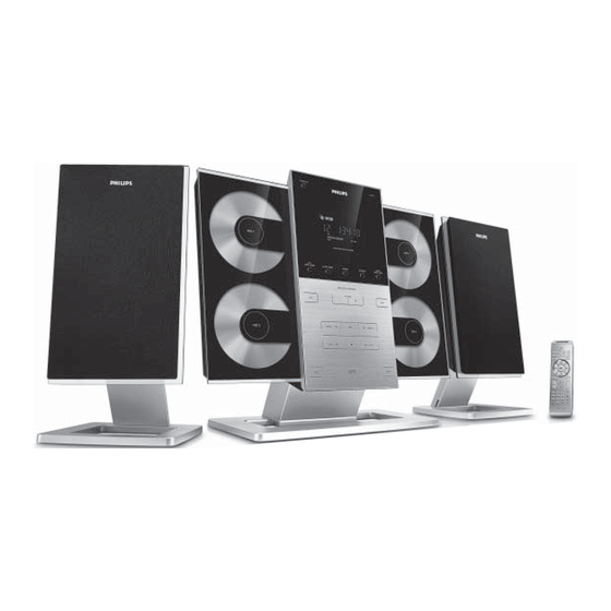
Philips MCM309R/37 Service Manual
Hide thumbs
Also See for MCM309R/37:
- Quick start manual (4 pages) ,
- Specifications (2 pages) ,
- Owner's manual (35 pages)
Table of Contents
Advertisement
Quick Links
See also:
Owner's Manual
Micro System
©
Copyright 2007 Philips Consumer Electronics B.V. Eindhoven, The Netherlands
All rights reserved. No part of this publication may be reproduced, stored in a retrieval system or
transmitted, in any form or by any means, electronic, mechanical, photocopying, or otherwise without
the prior permission of Philips.
Published by SL 0709 Service Audio
Version 1.0
TABLE OF CONTENTS
Location of PC Boards & Versions Variation ........................ 1-2
Specifi cations ....................................................................... 1-3
Measurement Setup ............................................................. 1-4
Service Aids, Safety Instruction, etc ...........................1-5 to 1-7
Preparations & Controls ........................................... 1-8 to 1-11
Disassembly Instructions & Service positions ......................... 2
Service Test Program .............................................................. 3
Set Block Diagram ................................................................... 4
Set Wiring Diagram ................................................................. 5
Main Board .............................................................................. 6
ECO 6 Tuner Board : Systems Non Cenelec ........................ 7A
Power Board ............................................................................ 8
Display (MCU) Board............................................................... 9
Key Boards ............................................................................ 10
Set Mechanical Exploded View & Parts List .......................... 11
Printed in The Netherlands
Subject to modification
MCM309R
Page
CLASS 1
LASER PRODUCT
© 3141 785 31640
/37
Advertisement
Table of Contents

Summary of Contents for Philips MCM309R/37
- Page 1 LASER PRODUCT © Copyright 2007 Philips Consumer Electronics B.V. Eindhoven, The Netherlands All rights reserved. No part of this publication may be reproduced, stored in a retrieval system or transmitted, in any form or by any means, electronic, mechanical, photocopying, or otherwise without the prior permission of Philips.
-
Page 2: Version Variations
LACATION OF PCBS VERSION VARIATIONS: Type /Versions: MCM309R Features & Board in used: Aux in / CDR in Line Out Video Out Surround Out Subwoofer Out Digital Out Digital in Matrix Surround RDS/NEWS Dolby Pro Logic (DPL) Incredible Surround Karaoke Features Voltage Selector ECO Power Standby (Clock Display Off) ECO6 Tuner Board - Systems Non-Cenelec... -
Page 3: Specifications
SPECIFICATIONS Input sensitivity GENERAL: Aux in (at 1kHz) : 500mV at 600 ohm Mains voltage : 110-127V/220-240V Switchable for /55/98 CD (Audio Disc1) : 0dB track (Trk 35) 117V ± 10% for /37 Tuner : FM67.5kHz DEV/AM 8 220V ± 10% for /61/93 Output sensitivity 230 ±... -
Page 4: Measurement Setup
MEASUREMENT SETUP Use Audio Signal Disc SBC429 4822 397 30184 (replaces test disc 3) L.P.F. = 13 order filter 4822 395 30204 Low pass filter 22kHz S/N and distortion meter e.g. Sound Technology ST1700B LEVEL METER e.g. Sennheiser UPM550 with FF-filter... -
Page 5: Service Aids
SERVICE AIDS ESD Equipment: Service Tools: Universal Torx driver holder .........4822 395 91019 Anti-static table mat - large 1200x650x1.25mm ...4822 466 10953 anti-static table mat - small 600x650x1.25mm ..4822 466 10958 Torx bit T10 150mm ...........4822 395 50456 Anti-static wristband ..........4822 395 10223 Torx driver set T6-T20 .........4822 395 50145 Connectorbox (1M Ω) -
Page 6: Esd Protection Equipment
WAARSCHUWING WARNING Alle IC’s en vele andere halfgeleiders zijn All ICs and many other semi-conductors are gevoelig voor electrostatische ontladingen (ESD). susceptible to electrostatic discharges (ESD). Onzorgvuldig behandelen tijdens reparatie kan Careless handling during repair can reduce life de levensduur drastisch doen verminderen. drastically. - Page 8 PREPARATIONS...
-
Page 9: Preparations & Controls
PREPARATIONS & CONTROLS... - Page 10 1-10 CONTROLS...
- Page 11 1-11 CONTROLS AND TROUBLESHOUTING...
-
Page 12: Dismantling Instructions
DISMANTLING INSTRUCTIONS Detaching the Stands from the Speakers and Main Sets To detach the stand from the main unit, Detach the speaker stands in the same way as a. As shown, hold down PRESS you do the main unit stand b. - Page 13 DISMANTLING INSTRUCTIONS Repair Hints & Service Positions Service position B 1) During repair it is possible to disconnect the Tuner Board Note: The flex cables are very fragile, care should be taken and/or CD Module completely unless the fault is sus- not to damage them during repair.
-
Page 14: Service Test Program
SERVICE TEST PROGRAM To hold ALBUM+ & PROGRAM depressed while set on standby Display shows the V refers to Version ROM version "Vy--y MTP xx-xx-2006" y--y refers to Software version number of the uProcessor (Main menu) (counting up from 01 to 99) xx refers to date number of the production. -
Page 15: Set Block Diagram
SET BLOCK DIAGRAM... -
Page 16: Set Wiring Diagram
SET WIRING DIAGRAM... -
Page 17: Main Board
MAIN BOARD TABLE OF CONTENTS Main PCB - Layout Top View ........... 6-2 Main PCB - Layout Bottom View ........6-3 Main PCB - Circuit Diagram (Audio Part) ......6-4 Main PCB - Circuit Diagram (CD Part) ......6-5 Class D Power PCB - Layout Top View ......6-6... -
Page 18: Pcb Layout - Main Board (Top View)
PCB LAYOUT - MAIN BOARD (TOP VIEW) -
Page 19: Pcb Layout - Main Board (Bottom View)
PCB LAYOUT - MAIN BOARD (BOTTOM VIEW) - Page 20 CIRCUIT DIAGRAM - MAIN BOARD AUDIO PART...
- Page 21 CIRCUIT DIAGRAM - MAIN BOARD CD PART...
- Page 22 11-1 11-1 MAIN SET MECHANICAL EXPLODED VIEW...
- Page 23 11-2 11-2 SUBWOOFER MECHANICAL EXPLODED VIEW...
- Page 24 11-3 11-3 MECHANICAL & ACCESSORIES PARTS LIST ELECTRICAL PARTSLIST 994000000308 996510001575 CONTROL PANEL AM/FM ANT (75OHM) ASS'Y 996510001562 MAIN BD ASS'Y MCM309R/37 996510001572 996510001554 FRONT LENS SUB BOX ASS'Y F302 ! 994000001222 FUSE RADIAL LT 2A 250V 996500040378 FRONT PANEL...


Need help?
Do you have a question about the MCM309R/37 and is the answer not in the manual?
Questions and answers