Table of Contents
Advertisement
INSTALLATION AND
OPERATOR'S MANUAL
IMPORTANT: IN ORDER TO ACHIEVE SAFE AND SATISFACTORY
RESULTS FROM YOUR ALTERNATE HEATING SYSTEMS BOILER, READ
SAFETY RULES AND INSTRUCTIONS CAREFULLY BEFORE
INSTALLING AND OPERATING. ALL INSTALLATIONS MUST BE IN
ACCORDANCE WITH STATE AND LOCAL CODES. SAVE THESE
INSTRUCTIONS FOR FUTURE REFERENCE.
ALTERNATE HEATING SYSTEMS
2393 LITTLE EGYPT RD
HARRISONVILLE, PA 17228
717-987-0099
WWW.WOODGUN.COM
EMAIL:SERVICE@WOODGUN.COM
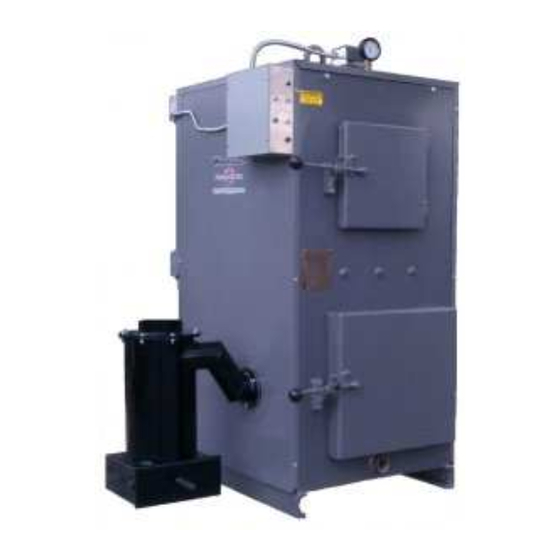
WOOD GUN™ WOOD GASIFICATION BOILER
Models: E100 SF • E140 SF • E180 SF • E250 SF
Your Alternate Heating Systems Boiler is capable of generating
very hot temperatures. Boiler temperatures and flames in the
ignition box area are capable of causing ignition or explosion of
explosive or flammable products or explosion of the boiler itself if
maximum safe water temperature is exceeded. Maximum safe
water temperature is 200° Fahrenheit. Flammable or explosive
products must never be stored in the same room or in the vicinity
of a boiler, and the boiler water temperature must never be
allowed to exceed 200° Fahrenheit.
Record Model and Serial Number Below:
Model:
Serial Number:
Date of Purchase:
Advertisement
Table of Contents

Subscribe to Our Youtube Channel
Related Manuals for Alternate Heating wood gun E100 SF


Summary of Contents for Alternate Heating wood gun E100 SF
- Page 1 ACCORDANCE WITH STATE AND LOCAL CODES. SAVE THESE INSTRUCTIONS FOR FUTURE REFERENCE. Your Alternate Heating Systems Boiler is capable of generating very hot temperatures. Boiler temperatures and flames in the ignition box area are capable of causing ignition or explosion of explosive or flammable products or explosion of the boiler itself if maximum safe water temperature is exceeded.
- Page 3 Copyright 2000 – 2015 Alternate Heating Systems. No portion of this publication may be reproduced without the express written consent of Alternate Heating Systems. Revision: 07/31/15...
-
Page 4: Table Of Contents
Table of Contents Introduction.................................1 Explanation of Wood & Biomass Combustion....................1 Wood Moisture Content & Wood Gasification....................1 Mode of Operation............................2 Boiler Installation..............................5 Boiler Location...............................5 Boiler Room Requirements........................5 Rigging and Positioning of Boiler........................6 Clearances to Combustibles Required for Safety and Operation..............6 Boiler Assembly.............................6 Cyclone Ash Collector..........................6 Air Valve..............................7 Draft-Inducing Fan Assembly........................7... - Page 5 EPA Side Tunnel Refractory Plug......................23 Particle Fuel Delivery Option........................24 Adjustment of the Draft-Inducing Fan (Belt-Drive Only)................24 Optional Automatic Fuel Delivery Systems....................24 Burning Particle Wood with a Low Moisture Content................25 Use of Water Spray Kit..........................25 Option and Sequence of Events for Automatic Feed Systems..............25 Augers..............................26 Photo-Eye Fuel Level Sensing System....................26 Wood Fuel Characteristics and Wood Storage.....................26...
-
Page 6: Introduction
All Alternate Heating Systems boilers can be WOOD MOISTURE CONTENT & WOOD supplied with the ASME “H” stamp and National... -
Page 7: Mode Of Operation
30% is optimum for burning wood in the gasi cation Wood with moisture content higher than 30% is process. more likely to produce condensation issues and will produce markedly less BTU’s per pound of Because of the downdra9 design of the Wood fuel. - Page 8 Alternate Heating Systems cannot promise stack as water vapor. Water will likely be evident in that summer time use of a Wood Gun will be the ash pan and, in severe cases, may even collect in practical for you.
- Page 9 water moisture in the wood, but is formed as a ✔ Increase run cycle length byproduct of combustion. Excellent combustion will ✔ Use drier fuel maximize the amount of the main byproducts of ✔ Clean boiler, or take other measures to combustion, carbon dioxide and water.
-
Page 10: Boiler Installation
Boiler Installation 2. A convenient water supply should be BOILER LOCATION available for boiler Gushing and to clean the Wood & Coal Burning Boilers are designed to boiler room Goor. radiate heat freely, but this heat can be dangerous if 3. -
Page 11: Rigging And Positioning Of Boiler
Alternate Heating Systems recommends that a quali ed technician experienced in boiler BOILER ASSEMBLY installations perform the installation of the Wood . -
Page 12: Air Valve
the boiler and connected as documented in the wiring diagram for the model being installed. Wiring diagrams are found in Appendix B. Draft-Inducing Fan Assembly e dra9-inducing fan assembly may be shipped in a separate box. See Fan Assembly in the Maintenance section for assembly guidance. -
Page 13: General Chimney Requirements
an aqua stat. Turn the dial 20° past the boiler water ✔ E100 to E180: not less than 6 IN diameter. ✔ E250 to E500: not less than 8 IN diameter. temperature. Use an ohmmeter to test the terminals for continuity. If the contacts are closed before you turn the dial it should open a9erward. -
Page 14: Flue Pipe
the boiler. In such situations, it may be important to additional restrictions and/or guidelines regarding provide for some heating of this air. your Gue pipe. PROPER CHIMNEY CONNECTION e boiler must be connected to a class A chimney. e recommended method for connecting the boiler to the chimney is to place a T-joint at the top of the vertical section leading from the cyclone. -
Page 15: Boiler Piping For Hydronic Systems
In installations where the chimney dra9 is too strong, the problem may be eliminated by allowing air to pass up the chimney from an auxiliary valve located at Goor level and connected to a “T”: in the Gue pipe or chimney. It is important to make provision for adequate supply of combustion air, either natural in ltration through or around a door or window, or by ducting... -
Page 16: Piping The Boiler In Parallel With Another Boiler
boiler near the front. Alternately, a “T” and short nipple could be a7ached to the return tapping for the location of the boiler drain. Piping the Boiler in Parallel with Another Boiler e Wood Gun™ may be connected to a heating system supplied by one or more boilers that are already in place. -
Page 17: Return Water Temperature
Speci cations to determine the water capacity of the liquid runo: in the boiler room. More seriously, it Wood Gun™ installed (do not use the BTU rating). will lead to creosote formation on heat exchange e expansion tank or air cushion tank that was surfaces and inside the chimney, with accompanying originally installed will not likely be adequate for the risk of a chimney re. -
Page 18: Recommended Boiler Control Settings In Hydronic Systems
e low water cut o: should be installed in the On Wood Gun™ models equipped with oil or gas supply riser just above the tapping of the boiler., as backup, the control se7ings should be as follows: shown above. Place a Tee 7ing 6” above the boiler ✔... -
Page 19: Forced Hot Air Systems (Water To Air Coil In Duct)
For steam systems other than gravity return consult Alternate Heating Systems for proper controls. Do not a7empt to connect two di:erent steam boilers in parallel since the water level in each boiler will not be the same. -
Page 20: Oil Burner Assembly
used when the Wood Gun™ is not being red (for example, in the summer). e diagram below indicates how this can be done. Plumbing – Coil in Parallel Plumbing – Coil with circulator OIL BURNER ASSEMBLY General Information If an oil burner is supplied with the Wood Gun™, connection of fuel lines and the adjustment of the In installations where the coil burner should be done by a quali ed oil burner... -
Page 21: Oil/Gas Burner Combustion Chamber: Models E100 And E140
gasket that is furnished with the burner is placed the air tube is back approximately ¼ in from the between the Gange of the Wood Gun™ and the inside of the ceramic lined chamber (see Figure 10) mounting Gange of the oil burner to prevent air Oil Burner Electrical Connection leakage. -
Page 22: Gas Burner Assembly
Alternate Heating Systems strongly recommends the unit be red on oil periodically to e burner mounts to the Gange on the boiler assure that the oil burner will function when needed. -
Page 23: Gas Burner Adjustment
gas, the system should be checked for leaks. is can below the kindling temperature for wood. In this be done by watching the ½ cubic foot test dial and case, the boiler must be manually switched back to allowing ve minutes to show any movement or by wood mode, and manually relit, in order to resume soaping each pipe connection and watching for wood burning. - Page 24 Photo: (Smoke flap installed) - 19 -...
-
Page 25: Operating Information
Operating Information Please read this entire manual before operating indicator light does not come on when the purge the boiler. It contains important requirements and timer is activated, it means the oil/gas burner is instructions must be followed for safe and ring and the door must not be opened. -
Page 26: Starting A Fire: Switch Positions
FUEL TYPE The Wood Gun is designed to burn split or unsplit wood e Wood gun is designed to burn log wood. Wood gun is able to burn both hard wood and so9 Do not remove the smoke flap in the wood fuel. -
Page 27: Charging The Boiler With Wood: Manual Feed
charge in su<cient quantity to last for up to ten indicator light is o:, push the green Purge bu7on or hours. Longer cycles are possible, but you will want turn the purge timer clockwise to number 5 and wait to plan for utilizing shorter burn cycles periodically two minutes before opening the door. -
Page 28: Epa Side Tunnel Refractory Plug
will have been dried down so that gasi cation can View Port) and observe the re. If you see Games occur at a very rapid rate when the unit resumes shooting upward inside the fuel chamber, consider active ring. Under these conditions there may be the above checklist items as your action list for insu<cient oxygen present to adequately burn all the preventing back pu<ng. -
Page 29: Particle Fuel Delivery Option
Once the kindling is going, add some larger chunk or Alternate Heating Systems also o:ers a VFD log wood. Be careful not to shi9 the diverter bricks (Variable Frequency Drive) option for the induction while loading the wood. -
Page 30: Burning Particle Wood With A Low Moisture Content
LT and LR photo sensors. Alternate Heating Systems suggests that a secondary e feed auger immediately shuts down while air system should be the rst choice for correcting the air lock continues cleaning itself until TDR –3... -
Page 31: Augers
Photo-Eye Fuel Level Sensing System e fuel level control system consists of a photoelectric beam generator, beam detector module, and time delay relay. e beam generator and detector are located on brackets on the cover of the air valve enclosure box. Never a7empt to adjust or disassemble any part of NOTE: It is important that the lens of both beam generator and the beam detector remain free of... -
Page 32: Removal And Disposal Of Ashes
the boiler. It is advantageous to let the sun remove burial in soil or otherwise locally dispersed, they that extra 100 to 250 gallons of water found in a cord should be retained in a closed container until all of wood. Generally, wood should be stored outdoors cinders have thoroughly cooled to prevent in a dry place with only a limited supply kept inadvertently starting a re. -
Page 33: Dissolved Oxygen
e pH factor is the most important factor (See h7p://www.p2pays.org/ref/34/33 027.pdf) inGuencing scale forming or the corrosive tendencies Solids can be categorized as either suspended or of boiler water. It should be adjusted to between a dissolved. Suspended solids are those that can be minimum of 9.0 and 11.0 to prevent acidic corrosion removed by ltration while dissolved solids are in of boiler tubes and plates and to provide for the... -
Page 34: Oils
which can cause the overheating of boiler plates. If Oils oil does get into the boiler, the boiler should Every e:ort should be made to prevent oils from immediately be taken out of service and thoroughly ge7ing into the boiler water. Oil causes foaming or cleaned. -
Page 35: Maintenance
Maintenance On models with dual dra9, use a pu7y knife or scraper inside the rebox. 8. Open the dra9 valve cover and inspect the valve gasket disk for evidence of air leakage. e disk should have some wobble, so it can move and nd its own seal. -
Page 36: Yearly Cleaning
place. In the locked position, cleaning and or ✔ Remove the top connecting Gange from the replacement of the air valve disc can be performed. cyclone. ✔ Clean the inside of the main body and funnel 5. To release the actuator, use the hex key wrench of the cyclone with a wire brush. -
Page 37: Door Adjustment
3. Manually move the air valve disc to the open position, (see Figure 12) ensure that the jaws on the clamp align with the contour of the sha9 as shown in Figure 11. 4. Tighten 10 mm bolt. 5. Using the Allen wrench, release the lock. is is accomplished by rotating the wrench in the direction of the arrow one quarter turn and then let go. -
Page 38: Load Door Seal Replacement
Door Hinge Plate Adjustment To adjust the latch side of the door, remove the two bolts that secure the latch keeper in place and remove one of the spacer shims. Shims are inserted at assembly. Remove the thin one rst and if more adjustment is required at a later time, then it can be used to replace the thicker one to gain the additional adjustment. - Page 39 Load Door with Fiberglass Braid Tape and More High Temperature Silicone 6. Start the gasket in the middle of the hinge side. Squeeze the gasket into place on top of the bead of silicone. e rounded side faces downward towards the silicone.
-
Page 40: Front And Rear Inspection Door High Temperature Rope Installation
as much as you can while pushing it in. Go from corner to corner until reaching the end. When pu7ing the two ends together tuck all loose ends down inside or between the rope ends. e rope should protrude about 3/8” above the door frame. 5. -
Page 41: Fan Assembly
Belt-drive fan assembly removed from boiler and showing white gasket Front Inspection Door FAN ASSEMBLY Be sure to disconnect power to the unit before servicing or removing e fan-motor assembly may be removed by the fan. loosening the nuts from the studs. If the fan assembly gasket is damaged, all of the old material must be removed and a new gasket inserted. -
Page 42: Direct Drive Fan Bearing Replacement Procedure
Note: Pillow block fan shaft bearings are permanently sealed. Do not force grease into the grease fittings as you will break the seal and grease will run out when heated. DO NOT use a clay based grease in the pillow block bearings. A good synthetic grease is the best option. - Page 43 AHS Fan Puller Tool at the Ready One Inch Nut for Pulling Fan Remove the (4) 5/16” nuts and washers from the Using a jaw type puller, remove the fan from the motor plate allowing you to remove the abrasion motor sha9: shield and the heat shield from the motor plate.
- Page 44 To separate the motor housing you must remove the four bolts from the end of the motor opposite of the sha9. ese bolts have a 5/16 bolt head. Motor Frame Assembly Bolts Once these bolts are removed, tap the mounting end of the motor on the side with a rubber mallet, or use a regular hammer along with a block of wood.
-
Page 45: Refractory Replacement
Center Brick refractory pieces should be changed every 10-15 cords of wood and must be ordered from Alternate Heating Systems. Center Brick are removed by simply li9ing them out. are likely to have become snug, as wood ash will se7le into voids around them, making them tight. - Page 46 Steel Center Brick – 8 Inch - 41 -...
-
Page 47: Side Brick Refractory Replacement
Please wear the proper safety equipment while SIDE BRICK REFRACTORY REPLACEMENT performing this task. Proper equipment includes, e large refractory (Side Bricks) are typically work gloves, safety glasses, and steel toe boots. replaced every 10-15 years in residential boilers. ey are usually held in place only by their own 1. -
Page 48: Fuel Diverter Blocks: Auto Feed Only
whether the # 4 bricks are installed on the right or on 4. Applying the Troweleze will be your last step. the le9. It ma7ers that all the numbers on the right e Troweleze will ll in the gap between the brick are the same, and all the numbers on the le9 are the and the vessel at the front and rear inspection door. -
Page 49: Appendix A: Boiler Specification Diagram
Appendix A: Boiler Specification Diagram - 44 -... - Page 50 - 45 -...
- Page 51 - 46 -...
-
Page 52: Additional Specifications
order to provide heating of a given number of ADDITIONAL SPECIFICATIONS degrees and at a certain BTU level: Pressure Drop 500K BTU’s at 20 degrees temperature • di:erential requires 50 gallons per minute. Pressure Drop (Line Loss) within the boiler is less than the pipe rating of the pipe within the boiler, so 250K BTU’s at 20 degrees temperature •... -
Page 53: Appendix B: Wiring Diagrams
Appendix B: Wiring Diagrams - 48 -... - Page 54 - 49 -...
- Page 55 - 50 -...
- Page 56 - 51 -...
- Page 57 - 52 -...
- Page 58 - 53 -...
- Page 59 - 54 -...
- Page 60 - 55 -...
-
Page 61: Appendix C: Exploded Parts Drawings
Appendix C: Exploded Parts Drawings - 56 -... -
Page 62: Parts Listing
Parts Listing KEY DESCRIPTION E100 SF E140 SF E180 SF E250 SF Domestic Hot Water Coil 100-002 100-002 100-002 100-002 Rear Insulation Jacket Rear Hinge Plate Mounting Bolt Rear Inspection Door Hinge Plate Rear Inspection door, complete 423-015 423-015 433-010 433-010 Rear Insp. - Page 63 - 58 -...
- Page 64 KEY DESCRIPTION E100 E140 E180 E250 61 Draft Box Lid Gasket 200-052-32 200-052-32 200-052-32 200-052-32 62 Right Side Insulation Jacket 63 Fiberglass Insulation 65 Exhaust Hood Attachment Bolts 66 Exhaust Hood Blower (wired) 67 Exhaust Hood Connecting Flange Assembly 68 Draft Motor 200-422B 200-422B 200-422B...
-
Page 65: Appendix D: Troubleshooting Guide
Appendix D: Troubleshooting Guide is guide is intended to help you diagnose and repair basic problems with you boiler. If you believe your problem is serious or the problem persists a9er following all the procedures speci ed in this guide, contact AHS for support. - Page 66 f) The boiler water temperature is too d) Burn smaller wood, split wood, low or Water temperature difference and/or dryer wood. Build a hotter between supply and return may be fire. Remember that more wood more than 20ºF does not always equate to more heat.
- Page 67 Wood Gun Air Inlet Ducting Installations....64 Marking to Trim............34 Wood Gun in Primary/Secondary System....65 Trimming Preformed Silicone Bead......34 Operating an Alternate Heating Systems Boiler in Adding High Temperature Silicone to Butt Joint of Tandem with Existing Boiler........66 Trimmed Bead............34 - 62 -...
-
Page 68: Appendix F: Boiler Piping And Ducting Examples
Appendix F: Boiler Piping and Ducting Examples - 63 -... - Page 69 Wood Gun Air Inlet Ducting Installations - 64 -...
- Page 70 Not all system components, valves and devices are shown in this drawing. Actual conditions and application requirements will vary. Please consult a heating expert or your Alternate Heating Systems for additional information.
- Page 71 Operating an Alternate Heating Systems Boiler in Tandem with Existing Boiler Note: The above illustrates one possible method of connecting the Wood Gun with an existing boiler. This connection is as follows: using a small circulator (and with the backup boiler piped into the return tapping) run another pipe from the supply tapping T, of the Wood Gun™...
-
Page 72: Limited Warranty
Dealer’s name Type of fuel burned 5) The OWNER and not Alternate Heating Systems or its dealers will be liable for the following costs involved in repair or replacement of the defective unit or component part All necessary costs in returning the defective unit or component part to the factory or other location designated by Alternate Heating Systems.
Need help?
Do you have a question about the wood gun E100 SF and is the answer not in the manual?
Questions and answers