Table of Contents
Advertisement
Quick Links
OPERATOR'S MANUAL
IMPORTANT: IN ORDER TO ACHIEVE SAFE AND SATISFACTORY
RESULTS FROM YOUR ALTERNATE HEATING SYSTEMS BOILER, READ
SAFETY RULES AND INSTRUCTIONS CAREFULLY BEFORE
INSTALLING AND OPERATING. ALL INSTALLATIONS MUST BE IN
ACCORDANCE WITH STATE AND LOCAL CODES. SAVE THESE
INSTRUCTIONS FOR FUTURE REFERENCE.
ALTERNATE HEATING SYSTEMS
2393 LITTLE EGYPT RD
HARRISONVILLE, PA 17228
717-987-0099
WWW.ALTERNATEHEATINGSYSTEMS.COM
EMAIL: SERVICE@WOODGUN.COM
INSTALLATION AND
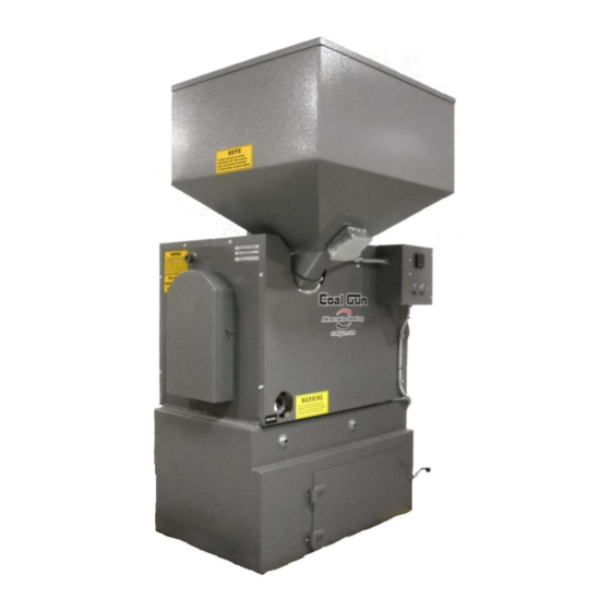
COAL GUN™ BOILER
Models: S130 • S260
Your Alternate Heating Systems Boiler is capable of generating
very hot temperatures. Boiler temperatures and flames in the
ignition box area are capable of causing ignition or explosion of
explosive or flammable products or explosion of the boiler itself if
maximum safe water temperature is exceeded. Maximum safe
water temperature is 210° Fahrenheit. Flammable or explosive
products must never be stored in the same room or in the vicinity
of a boiler, and the boiler water temperature must never be
allowed to exceed 210° Fahrenheit.
Record Model and Serial Number Below:
Model:
Serial Number:
Date of Purchase:
REV 170126
Advertisement
Table of Contents

Related Manuals for Alternate Heating COAL GUN S130


Summary of Contents for Alternate Heating COAL GUN S130
- Page 1 ACCORDANCE WITH STATE AND LOCAL CODES. SAVE THESE INSTRUCTIONS FOR FUTURE REFERENCE. Your Alternate Heating Systems Boiler is capable of generating very hot temperatures. Boiler temperatures and flames in the ignition box area are capable of causing ignition or explosion of explosive or flammable products or explosion of the boiler itself if maximum safe water temperature is exceeded.
- Page 3 Copyright 2015 Alternate Heating Systems No portion of this publication may be reproduced without the express wri en consent of Alternate Heating Systems. Printed: 12/26/17 Coal Gun boilers are optionally available with the ASME H stamp. It is the customer's...
-
Page 5: Table Of Contents
Table of Contents Introduction................................1 Boiler Installation..............................2 boiler location..............................2 Boiler Room Requirements..........................2 Rigging and Positioning of Boiler........................2 Clearances Required for Safety and Operation....................3 General Chimney Introduction..........................3 Draft................................4 Technical Aspects of Chimney Performance....................4 Barometric Damper - Draft Controls........................5 How Draft Controls Work..........................6 Choosing the Right Size Draft Control......................6 Stovepipe................................7 Proper Chimney Connection..........................7... - Page 6 Caution.................................23 Operation of Sight Hole Flap..........................23 Shutting Down the Coal Gun..........................24 Automatic Fuel Delivery Systems........................24 Basic Auger Operation..........................24 Auger assembly............................25 Thermo Ash-Monitoring Grate Control Operation...................25 Fuel storage / Removal and Disposal of Ashes....................25 treatment of Boiler Water..........................26 Ph..................................26 Dissolved Oxygen............................26 Sulfites................................26 Solids................................26 Alkalinity..............................27...
-
Page 7: Introduction
All Alternate Heating Systems Boilers can be comply with all requirements of AHS. Should your supplied with the ASME “H” stamp and National installation require a steam boiler, it is even more... -
Page 8: Boiler Installation
Boiler Installation continuous supply of air, it is essential that BOILER LOCATION provisions are made to supply adequate air to Coal Boilers radiate heat from multiple surfaces. the boiler room. /is air supply is necessary /is heat can be dangerous if the boiler is improperly to insure complete combustion and venting of installed. -
Page 9: Clearances Required For Safety And Operation
A ratchet puller (come along) device may be NOTE: This unit is not approved or recommended needed to move a boiler where the ground level for use in mobile homes. changes in elevation. AHS suggests that professional movers should be used in any unpredictable situation. -
Page 10: Draft
NOTE: For insurance and building code compliance check with your local building inspector and insurance agent. Draft Natural draE in a chimney results from several factors. /e main characteristic of draE is lower pressure at the top opening of the chimney than further down. -
Page 11: Barometric Damper - Draft Controls
Barometric Damper NOTE: The information in the rest of this section Dwyer Manometer is provided by Field Controls, LLC, Kinston, North Carolina, 252.522.3031. This information is used with their permission. Some information may not BAROMETRIC DAMPER - DRAFT CONTROLS apply to coal burning systems. The information is taken from Field Controls, LLC website at: www.fieldcontrols.com/draftcontrol.php. -
Page 12: How Draft Controls Work
If the draft regulator is set too high it can cause the coal fire to burn out of control. NOTE: See diagram below which has been modified for this manual. Draft Control How Draft Controls Work 1. Static pressure from the cooler air around the Choosing the Right Size Draft Control boiler exerts pressure on the outside of the furnace If a barometric damper is required, use these... -
Page 13: Stovepipe
breaching. When chimneys are of an unusual height or if the draE to be maintained is either very high or very low, it is advisable to deviate from the rules of thumb outlined here. Refer to the larger table (following page). The airflow through the system and Nominal Cross-Sectional Control Size... - Page 14 (304 or 316). /e minimum @ue diameter for an S130 that accumulates. If the horizontal run to the is 5 inches and an S260 is 6 inches. chimney is inclined more steeply, it will encourage any @y ash that would otherwise be deposited in the pipe to fall back into the ash separator.
-
Page 15: Wall Pass-Through: United States
Particular a ention should be paid to the point /is method is illustrated. For details on the other where a @ue passes through a wall or ceiling. /e three options, refer to the most recent edition of the pass-thru should always be made with insulated pipe NFPA 211 code. -
Page 16: Masonry Chimneys
temperature (650 degrees C) chimney standard, ULC manufacturer’s recommendations. A manufacturer’s S-629, or with a code approved masonry chimney. Wall Support Kit (D) will contain required items for supporting the chimney. Such kits will cost less than Masonry Chimneys individual items purchased separately. A Bo om Cap If you plan on using a preexisting masonry (E, location marked, but actual cap not shown) chimney, have it thoroughly inspected and cleaned. -
Page 17: In Case Of Chimney Fire
approved Chimney Pipe Adapter (K) is required. A Ceiling Support (L) will provide structural support for the chimney and is typically part of a kit that includes items that maintain required clearances to @ammables. A Storm Collar (M), and Adjustable Flashing (N) prevent water from entering the home by running down the outside of the chimney. -
Page 18: Boiler Piping For Hydronic Systems
/e washout plugs in the bo om of the suIcient diameter for the boiler to be used. Contact unit are a requirement of the ASME boiler code and Alternate Heating Systems if an outside air ducting must be closed before 1lling the unit with water. kit is required. -
Page 19: Pressure Relief Valve
/e installation should comply with Expansion Tank ✔ requirements of CAN/CSA-B365, and changes to the installation should comply with CSA B139 (for oil-1red), C22.1 (for electric), or CAN/CGA-B149.1 or CAN/CGA-B149.2 (for gas-1red). Pressure Relief Valve It is very important to provide /e pressure relief valve is factory installed into adequate expansion tank capacity a 1 ing on top the boiler. -
Page 20: Boiler Piping And Controls For Steam Systems
boiler. When 1lling your boiler with water for the system. If the boiler cannot meet this capacity, there 1rst time, mix contents of each bo le with 2 gallons will be areas that do not receive heat. of warm water. Pour into any suitable boiler Steam boilers also have a diDerent wiring opening. -
Page 21: Illustrated Instructions For Installing Coal Hopper On S130 And S260
Plumbing – Coil in Series A second method of plumbing the domestic coil is to connect the coil in parallel with an existing water heater so that the conventional water heater Tempering valve may be used when the Coal Gun™ is not being 1red /e third method of plumbing the domestic coil (for example in the summer). -
Page 22: Electrical Connections In The Coal Gun Tm
Coal Inlet Tube: Seen Without Hopper Hopper Temperature Safety Switch: Cover Replaced Step 3: Insert hopper tube into the hopper collar Step 6: Connect/reconnect power. and tighten screws until snug. Make sure that the hopper is level or adjusted to your preference. ELECTRICAL CONNECTIONS IN THE COAL All hydronic Coal Guns are prewired to maintain boiler water temperature at approximately 180°... -
Page 23: Controls
/e operating limit is designed to maintain boiler temperature under normal operating conditions by turning the draE fan on and oD. /e range for this control is from 150° F to 180° F. /e normal factory se ing is 180° F. /e dump zone temperature control is designed to operate one or more heat zones to prevent high boiler temperatures from occurring during low load... -
Page 24: Grate Timers And Settings
reading indicated at SV, there will be a call for the In addition to a higher position for the 1re, a grates to cycle on, operating until ash temperature lower se ing on the /ermal Ash Monitoring climbs to the SV value. Whether the grates will be Control will also mean deeper ash under the 1re and actually observed to be running at this time will more opportunity for coal to burn completely before... - Page 25 timers. Your boiler's factory se ings on the internal hopper, triggering the heat sensor, which will turn timers are already quite adequate for most situations. oD the boiler. /e same can happen if the grate Rarely, it may be necessary to adjust the timer to switch is leE oD too long.
-
Page 26: Thermostat Connection
until temperatures fall suIciently. See Appendix H for a variety of dump zone wiring examples. If the dump zone is connected to provide heat to a domestic hot water tank or heat exchanger, a mixing valve must be installed on the potable system supply to prevent an unsafe condition of overheating the domestic hot water. - Page 27 /is arrangement will allow a gravity @ow of heat release in the event of a power failure. For other dump zone applications, see Appendix H. Figure 9: Non-Powered Dump Zone - 21 -...
-
Page 28: Operating Information
/e S130 and S260 Coal Gun™ are furnished with a single ash tub. An extra tub can be obtained LIGHTING THE COAL GUN from Alternate Heating Systems. The use of emergency power from a backup generator is necessary for operating the Coal during a power failure. -
Page 29: Caution
Do not store fuel or other combustible Sight Tube Cover Removed • material within marked installation clearances. Inspect and clean @ues and chimney regular. • Caution Unit is HOT while in operation. • Do not touch during operation. • Do not operate without the hopper lid, site •... -
Page 30: Shutting Down The Coal Gun
seat automatically and held there during the time the the main switch. Keep in mind the boiler draE motor fan runs. /is is necessary to force combustion air will continue to run aEer the coal is used up until the through the 1re bed rather than across the top. -
Page 31: Auger Assembly
OD – disables auger function (middle suspension from the ceiling or overhead structural • position) framing so that the weight of the auger does not rest on the hopper lid. Manual – /is position energizes the auger at • all times (for maintenance only) Automatic –... -
Page 32: Treatment Of Boiler Water
Below a Ph of 5.0 the water is acidic enough to Note: Burn Pea Or Buckwheat Size Anthracite dissolve the steel boiler plates. Under these Coal Only! conditions the steel gradually becomes thinner and thinner until it is destroyed. At a Ph between 5 and Ashes should be placed in a metal container with 9.4 pi ing of steel plates will occur at a rate a tight 1 ing lid. -
Page 33: Alkalinity
for the control of solids through the use of blow Hardness down. /e hardness of water is caused by calcium and Another test that is sometimes used as a measure magnesium ions. Water hardness will vary greatly of solids is to measure the chloride present in the throughout the country depending on the source of boiler water. -
Page 34: Appendix A: Boiler Specification Diagrams
Appendix A: Boiler Specification Diagrams - 28 -... - Page 35 - 29 -...
-
Page 36: Additional Specifications
in order to provide heating of a given number of ADDITIONAL SPECIFICATIONS degrees and at a certain BTU level: Pressure Drop 500K BTU’s at 20 degrees temperature • diDerential requires 50 gallons per minute. Pressure Drop (Line Loss) within the boiler is less than the pipe rating of the pipe within the boiler, so 250K BTU’s at 20 degrees temperature •... -
Page 37: Appendix B: Wiring Diagrams
Appendix B: Wiring Diagrams - 31 -... - Page 38 - 32 -...
- Page 39 - 33 -...
-
Page 40: Appendix C: Exploded Parts Drawing
Appendix C: Exploded Parts Drawing - 34 -... -
Page 41: Parts Listing
Parts Listing (As shown in diagram on previous page) 1. Hopper Lid 2. Coal Hopper 3. DraE Inlet Cover 4. DraE Inlet Flap 5. Right Insulation Cover 6. Grate Base Door (one on each side)+ 7. Grate Assembly 8. /ermocouple for /ermo-Controlled Grates 9. -
Page 42: Appendix D: Maintenance
Appendix D: Maintenance /e Alternate Heating Systems Coal Gun designed to provide years of reliable service. Nevertheless, it is necessary to provide basic service in order to maintain optimum eIciency and service from your boiler. We recommend that you have your authorized Alternate Heating Systems dealer provide the seasonal preventative maintenance service. -
Page 43: Cleaning Rear Of Heat Exchanger
result in lower performance for the Coal Gun. Annual cleaning will help maintain like new performance. Square Swirl Tube Exit Port To clean through this opening with a vacuum hose, choose a hose that represents the largest Removing Fan Assembly diameter that will pass easily through the hole. -
Page 44: Cleaning Coal Pot, Feed Tube And Grate
for cleaning. Long handled brushes and the AHS Swirl Tube Scraper are good tools to have ready at hand for this. /e following photo shows the Swirl Tube Scraper for the S130 Coal Gun in use. It features a curved scraper head that matches the curvature of the heat exchanger. -
Page 45: Fan Assembly Removal/Repair
AEer the initial burn of two to assembly or heat exchanger area. We recommend six hours shut the boiler down and retighten the you contact Alternate Heating Systems for this pillow block bearing set screws. To tighten the fan repair procedure. - Page 46 Note: Mark connections before disconnecting wires. 2. Remove the four nuts, which hold the fan assembly to the boiler. /ese are the outer circle of nuts on the fan plate. 6. Using a manual jaw puller a ached to the 1- inch nut, carefully pull the fan from the motor shaE.
-
Page 47: Direct Drive Motor Bearing Replacement
10. A ach fan assembly to boiler and reconnect the wires. DIRECT DRIVE MOTOR BEARING REPLACEMENT /is guide may be used for replacement of direct drive induction fan motor bearings. We recommend you contact your Alternate Heating Systems for this repair procedure. - 41 -... - Page 48 5. Using a hex key (allen wrench) remove the 4 8. Set motor on back, shaE end up, on a countersunk screws, which hold the fan plate to the workbench. motor. 9. Using a small hammer, gently tap up on the end plate at shaE end.
-
Page 49: Additional Information
13. Using a manual jaw puller, remove bearing from shaE. 11. Check to be sure the beveled (cupped spring) washer stayed in the end cap remaining with the motor housing. 12. Remove the two screws holding the bearing to the front end cap and gently tap end cap oD. 14. -
Page 50: Operation And Maintenance Schedule For Models S130 And S260
Operation and Maintenance Schedule for Models S130 and S260 Interval Item Procedure As Needed Ash removal Remove ash and observe condition of ash. Adjust grate timer if necessary. Weekly Fire bed (when burning poor quality Check for clinkers and remove if coal) necessary. -
Page 51: Appendix E: Troubleshooting Guide
Appendix E: Troubleshooting Guide - 45 -... - Page 52 Problem Possible Cause Solution a) Sight hole cover flap not releasing a) Check spring for proper tension when fan stops b) Install barometric damper in flue 1.Boiler overheating b) Excessive chimney draft c) Reduce aquastat setting or replace c) Aquastat set too high or aquastat malfunctioning a) Add expansion tank capacity...
-
Page 53: Checking/Removing Clinkers
and on belt drive systems, increasing the velocity of CHECKING/REMOVING CLINKERS the induction fan with non factory pulley arrangements. Clinkers can be reduced or eliminated by changing the se ings of the ash controller on the boiler. Clinkers that are approximately baseball size or smaller will be carried to the ash pan. -
Page 54: Appendix F: Table Of Figures
Appendix F: Table of Figures - 48 -... -
Page 55: Appendix G: Programming Grate Control
Appendix G: Programming Grate Control Note: Your grate control comes preprogrammed from the factory. If you merely wish to change the temperature (set value, SV) at which the grate operates, this is accomplished by going directly to step 5 on the next page (Setting Grate Operation Control): - 49 -... -
Page 56: Dwyer 16C-2 Programming
DWYER 16C-2 PROGRAMMING Initial Programming 1. Selecting Input Type button for three seconds, until you see: B. Scroll with 2. Setting Temperature Unit button for three seconds, until you see: C. Scroll with until Fahrenheit is selected D. Press twice 3. -
Page 57: Appendix H: Dump Zone Wiring Applications
Appendix H: Dump Zone Wiring Applications - 51 -... - Page 58 - 52 -...
- Page 59 - 53 -...
- Page 60 - 54 -...
- Page 61 - 55 -...
- Page 62 - 56 -...
-
Page 63: Appendix I: Boiler Piping Examples
Appendix I: Boiler Piping Examples - 57 -... - Page 64 Not all system components, valves and devices are shown in this drawing. Actual conditions and application requirements will vary. Please consult a heating expert or your Alternate Heating Systems dealer for additional information.
- Page 65 Note: The above illustrates one possible method of connecting the Coal Gun™ with an existing boiler. This connection is as follows: using a small circulator (and with the backup boiler piped into the return tapping) run another pipe from the supply tapping T, of the Coal Gun to the supply line, of the existing boiler on the lower side of the flow control valve.
-
Page 66: Limited Warranty
2) If said dealer cannot be located, contact any other Alternate Heating Systems dealers in your area. 3) If you are unable to locate a dealer, submit your warranty claim directly to Alternate Heating Systems at the address listed below.
Need help?
Do you have a question about the COAL GUN S130 and is the answer not in the manual?
Questions and answers