
Related Manuals for ACT'L eWON4001


Summary of Contents for ACT'L eWON4001
- Page 1 Ethernet Gateway Remote Access Server (RAS) Programmable Industrial Router (PIR) Installation Guide Rev. 2.1 Cool Internet Telecontrol Solutions...
-
Page 2: Table Of Contents
1.1 Introduction ..............1 1.2 General specification of the hardware platform ....1 1.3 Functions of the eWON4001™ Ethernet Gateway....1 1.4 Functions of the eWON4001™ RAS Modem RAS & PIR..1 1.5 Datalogger..............2 1.6 Typical applications ............2 1.7 Part Numbers and internal options ........ - Page 3 Ethernet Gateway Remote Access Server (RAS) Programmable Industrial Router (PIR) 5.6 Configurable serial port ..........15 5.7 MPI port ...............16 5.8 Digital input ..............17 5.9 Digital output ..............18 6 Communicating with the eWON ........19 6.1 By Ethernet..............19 6.2 By phone line or GSM .............19 7 IP parameters configuration ..........
-
Page 4: Product Description
It is secure because it meets the toughest industrial standards and has restricted access features (required in open networks). The hardware platform of the eWON4001™ is a standard eWON that embeds a modem (PSTN or GSM/GPRS). -
Page 5: Datalogger
Part Number structure of the eWON product range: EWaabzm Where (examples): aa = Type of hardware platform • 41 = eWON4001™ b = Power supply • 2 = Low voltage DC power supply z = Serial port type • 0 = RS232 / RS422 / RS485 serial port •... -
Page 6: External Accessories
Installation Guide ver 2.1 Available Part Numbers for the eWON4001™ platform: Type/Description Part Number eWON4001™/Ethernet only (No modem) EW41201 eWON4001™/PSTN56 (PSTN modem) EW41203 ™ eWON4001 /ISDN (ISDN modem) EW41203 eWON4001™/GSM/GPRS (GSM/GPRS modem) EW41205 eWON4001™/GSM/GPRS US (GSM/GPRS modem) EW41206 eWON4001™/PSTN 56LS (PSTN 56LS modem) EW41209 eWON4001™/PSTN56 (PSTN) with MPI port... -
Page 7: Structure Of The Ewon Technical Documentation
Installation Guide ver 2.1 2 Structure of the eWON technical documentation The eWON technical documentation is structured in 4 different levels as shown in the table below: Level Title Contents Detailed description of the hardware platform, of its interfaces, available options and accessories. -
Page 8: Housing And Markings
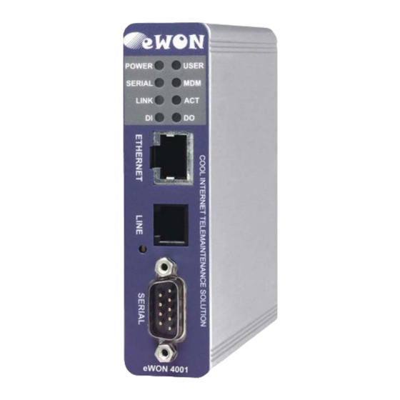
Installation Guide ver 2.1 3 Housing and markings 3.1 Housing Interfaces Leds Ethernet port 10/100 Base Tx Phone line Reset button Configurable serial port DIN rail latch Figure 1: Housing, front view Power supply Digital I/O 12-24 VDC Figure 2: Housing, bottom view... -
Page 9: Markings
Later style label Serial number 1247 = year+week 0001 = sequential number 66 = suffix eWON4001MPI/ETH V1 88 = suffix eWON4001/ETH V1 89 = suffix eWON4002/ETH V1 91 = suffix eWON4001/ETH V2 Required power supply The power supply must be limited to... -
Page 10: Equipment Information And Versions
Installation Guide ver 2.1 The eWON Serial Number (SN) is an important traceability tool both for the user and for the manufacturer. Therefore, next to the product label, each eWON has its serial number stored in the flash memory. This SN is also used in order to scan the network for eWONs and to assign its IP address, subnet mask and gateway. - Page 11 Installation Guide ver 2.1 Important note regarding hard- and firmware compatibility: There are two hardware generations of eWON500, namely V1 and V2. The V2 models are identified as such on their labels. They also have different PCODES (SN-Suffix). The firmware version 6.4s5 is compatible with both V1 and V2 hardware. Earlier firmware versions are only compatible with the V1 hardware, while firmware versions greater than 6.4s5 are only compatible with the V2...
-
Page 12: Mechanical Outline
Installation Guide ver 2.1 3.4 Mechanical outline 26 mm Upper slider Latch Figure 5: Left: Mechanical Outline - Right: DIN-rail latch The eWON must be fastened on a 35mm DIN rail compliant with EN50022. A fixing latch is therefore fastened at the bottom of the housing in order to put the device in place or remove it. -
Page 13: Mounting And Environmental Conditions
3.7 Specification for external power supply selection The eWON4001™ has to be supplied by an external voltage source ranging from 12 to 24 VDC. The power supplied must be a Class2 or Level 3, SELV-compliant (security voltage) and limited in current to a max of 500mA. The safety voltage power supply is not part of the delivery. -
Page 14: Front Panel Control Leds
Installation Guide ver 2.1 3.7.1 Auto fuse An auto fuse placed just after at the power input protects the eWON devices against short circuits. This component returns by itself to its normal state when the short circuit has disappeared and after the component has been cooling down. -
Page 15: Embedded Pstn Modem
Installation Guide ver 2.1 5.2 Embedded PSTN Modem Specification PSTN 33 PSTN 56 LS Max baud rate (V34) 33.600 bps (V92) 56.000 bps 47 CFR part 68 (USA) Compliant to standards CTR-21 (EUR) Approved by TÜV Rheinland USA Certificate number... -
Page 16: Embedded Isdn Modem
Installation Guide ver 2.1 5.3.2 SIM-card installation SMA antenna connector SIM-card drawer Eject SIM-card button Figure 7: SIM-card insertion 5.4 Embedded ISDN Modem Specification Value ISDN specification ISDN BRI S0.I.430 Type 1B+D Max baud rate 64 Kb Certification Table 10: ISDN modem specification... -
Page 17: Resets
Installation Guide ver 2.1 5.5 Resets Warning: you should not reset your eWON unless you have been told to do so by someone of our technical support. The concerned files (differs depending on reset type) are totally lost and unrecoverable after being formatted. -
Page 18: Configurable Serial Port
Installation Guide ver 2.1 5.6 Configurable serial port Specification Value Physical modes (configurable) RS232/RS485/RS422 Normal isolation Non isolated Optional isolation module (optocoupler) 1 kV Max serial cable length in non-isolated configuration See label and appendix (Serial Port (optional) on page... -
Page 19: Mpi Port
Installation Guide ver 2.1 5.7 MPI port The MPI port is easily identifiable with its blue square surrounding the gender-changer dongle. Specification Value Physical mode • 19.2 kBauds • 187.5 kBauds Speed • 1.5 MBauds Polarisation 680 Ohms (selectable) -
Page 20: Digital Input
Installation Guide ver 2.1 5.8 Digital input Specification Value Input voltage range 0 to 24 VDC Input voltage absolute max 33 VDC (varistor protection) Zero state max input voltage (OFF) 5 VDC One state voltage range (ON) 10 to 30 VDC 3.8mA @ 12VDC... -
Page 21: Digital Output
Installation Guide ver 2.1 5.9 Digital output Specification Value Type of output Open collector Max current (external source) 200mA @ 30 VDC Isolation 3,5 kV Pinout connector See label and appendix (Input/Outputs on page 27) Table 14: Specification of the digital output This digital output is activated by an open collector transistor driven by an optocoupler. -
Page 22: Communicating With The Ewon
Installation Guide ver 2.1 6 Communicating with the eWON 6.1 By Ethernet 1 ) Plug one of the Ethernet cables [see appendix (Direct connection on page 24 and Connection over hub/ router on page 25)] between your eWON and either your PC (crossed cable) or onto your network (straight cable). - Page 23 Installation Guide ver 2.1 13 ) You can now access the different Web pages of the eWON and, among others, configure your connection parameters by selecting the following options in the menu of the home page: To configure the Ethernet IP address: <Configuration>, <System Setup>, <Communication>, <Ethernet>...
-
Page 24: Ip Parameters Configuration
Installation Guide ver 2.1 7 IP parameters configuration Warning: parameters always have to be defined in full agreement with the network policies applicable within your organisation (ask your network administrator). The Ethernet port of the eWON is configured in the factory with the following default parameters: •... -
Page 25: Technical Support
Installation Guide ver 2.1 8 Technical support If you need technical support, simply fill out the form on the Web site http://www.ewon.biz or send an email with the problem description to support@ewon.biz. Appendix: Pinouts and connections 9.1 Power Supply Figure 10: eWON Mating female connector (included) •... -
Page 26: Ethernet
Installation Guide ver 2.1 9.2 Ethernet The eWON can be accessed by a 10/100BaseTX Ethernet connection. This connection can be made with two different cables (straight or crossed). These cables have 8 copper conductors and are known as UTP Class 5 with RJ45 terminations at both ends. - Page 27 Installation Guide ver 2.1 9.2.1 Direct connection If the eWON is connected directly to a PC, then use the crossed cable: Crossed cable When cabling over long distance, you have to take care of the twisted pairs. This means that along with the above...
- Page 28 Installation Guide ver 2.1 9.2.2 Connection over hub/router If the eWON is connected to a hub, it has to be connected like any other device, with a straight cable. Again, the wiring is as shown on the following picture, and care should be taken to keep the RX and TX signals on twisted...
-
Page 29: Rj45 Connector
Installation Guide ver 2.1 9.3 RJ45 connector The RJ45 connector has got the following pins numbering, as it can be seen on the following picture, showing it from different angles: page 26 of 31... -
Page 30: Input/Outputs
Installation Guide ver 2.1 9.4 Input/Outputs Mating female connector (included): Manufacturer: Sauro http://www.sauro.net/ Part Number: CTF050VT Description Output digital signal (0V ground) DO_GND connected to the emitter of the transistor Output digital signal connected to the DO_OC collector of the transistor... -
Page 31: Serial Port (Optional)
Installation Guide ver 2.1 9.5 Serial Port (optional) Mating female connector (not included): Type Female DB9 with 4/40 blocking screws Pinout serial port (according to mode): RS232 RS485 RS422 Table 16: Pinout serial port page 28 of 31... -
Page 32: Mpi Port (Optional)
Installation Guide ver 2.1 9.6 MPI port (optional) Mating male connector (not included): Type Male DB9 with 4/40 blocking screws MPI port pinout (DB9 female): B(+) A(-) Table 17: MPI port page 29 of 31... -
Page 33: Unitelway/Modbus Serial Cable
Installation Guide ver 2.1 9.7 Unitelway/Modbus serial cable This 2m cable can be delivered as accessory to connect Schneider PLCs; It has a SUBD9 connector at the eWON side and a MiniDIN connector at the PLC side. Schneider MiniDIN PIN... -
Page 34: Pstn Phone Line Connector
Installation Guide ver 2.1 9.8 PSTN phone line connector Mating male conector (not included): Type: RJ11 type "6P2C" without shield Pinout PSTN line: Description RING Table 19: pinout PSTN modem page 31 of 31...
Need help?
Do you have a question about the eWON4001 and is the answer not in the manual?
Questions and answers