
Related Manuals for IRadimed MRIDIUM 3860+


Summary of Contents for IRadimed MRIDIUM 3860+
- Page 1 3860+ 3860+ REF 1138 REF 1138 MRidium MRI INFUSION/MONITOR SYSTEM OPERATION MANUAL OPERATION MANUAL IRADIMED IRADIMED CORPOR CORPORATION TION...
- Page 3 MRidium 3860+ MRI Monitor/Infusion System Operation Manual, Part Number 1138 Release 4B, 2015-10 PER ECN 000711 © 2010-2015 IRadimed Corporation IRadimed Corporation 1025 Willa Springs Drive Winter Springs, Florida 32708 U.S.A. Tel 407-677-8022 Fax 407-677-5037 www.iradimed.com European Authorized Representative Medical Device Consultancy...
-
Page 5: Table Of Contents
CONTENTS Paragraph Page General Information ................. vi Equipment Classification ..............vi Intended Uses / About the Pump ............ vii Warnings / Precautions..............viii User Responsibility ................xiv Definitions..................xiv Symbols ..................xv Introduction ................... 1-1 Product Description................1-1 1.1.1 Front of the Pump .............. - Page 6 I.V. Set Preparation for Use ............3-1 Precautions..................3-1 I.V. Set Priming ................3-2 3.2.1 I.V. Administration Set 1056 Priming .......... 3-2 3.2.2 I.V. ByPass Set 1055 Priming ............. 3-2 3.2.3 I.V. Syringe Adapter Set 1057 Priming ........3-2 3.2.4 I.V. Extension Set 1058 Priming ..........
- Page 7 Battery Operation ................6-1 Introduction..................6-1 Inserting the Battery Pack ..............6-1 Charging the Battery Pack ..............6-1 Removing the Battery Pack ..............6-2 Testing the Battery Pack..............6-2 Battery Charge Indicator ..............6-3 Battery Low Indication ............... 6-3 Battery Power Gauge .................
- Page 8 Specifications ..................A-1 Repair .....................B-1 Warranty information ................C-1 Manufacturers Technical declaration ............D-1 IV Sets and Accessories................E-1 Troubleshooting ..................F-1 1119 I.V. Pole Assemblies and Parts descriptions........G-13 Trumpet and start up curves..............H-1 Appendix A: Specifications ..............A-1 Appendix B: Repair ..................B-1 Appendix C: Warranty information............C-1...
- Page 9 FIGURES Figure Page Front of Pump ................... 1-2 Pump Drive Door Open............... 1-3 Back of Pump..................1-4 Model 1120 MRI Power Supply ............1-5 Front of 3865 Remote Display/Charger ..........1-6 Back of 3865 Remote Display/Charger..........1-7 Front Panel Control Keys ..............
-
Page 10: General Information
General Information This document provides the following directions for use: • Single channel pump that provides a full range of features in a compact, easy to use, linear peristaltic pump. • Dual channel pump offers the same features while providing two independent infusion pumps in one instrument. -
Page 11: Indications For Use
About the Pump: Intended Uses Indications for Use: The Iradimed Corporation's MRidium 3860+ MRI Infusion Pump/Monitoring System is intended for general hospital or clinical use by medical professionals whenever it is required to infuse patients with subcutaneous, intra-venous or intra-arterial fluids before, during, or after Magnetic Resonance Imaging (MRI) scans, functioning while either in a stationary or mobile position. -
Page 12: Warnings/Precautions
The Remote Display Charger is intended for use in the MRI control room. Do not operate the 3865 Remote Display/Charger inside the MRI Magnet Room. For safe operation, use only Iradimed Corporation recommended MRI-compatible or MRI-safe accessories. The MRI pump must be mounted securely when used in the MRI scan room. Always securely mount the pump using it’s integral pole mount clamp or other mechanical... - Page 13 Precautions/Continued Arrange tubing, cords and cables to minimize the risk of patient or other equipment entanglement. The pump is not intended for high pressure, high viscosity radiological contrast agents. To avoid patient injury, always respond to Pump or Remote Display/Charger alarms immediately.
- Page 14 Pump Related Warnings/Precautions (Continued) If questionable Pump operation is observed, or if a System Failure occurs (i.e. an unexplained continuous audible alarm with no displayed values), discontinue use of the Pump and refer it to qualified service personnel. Although unlikely, failure of certain rugged mechanical components, such as the free-flow prevention mechanism could cause fluid delivery limited to the contents of the fluid container.
- Page 15 Set Related Warnings/Precautions Always use aseptic techniques. Patient infection could result from mishandled or non-sterile assemblies. Use only Iradimed Corporation MRidium 1000 Series administration sets. The use of other sets will cause improper pump operation resulting in inaccurate fluid delivery. MRidium...
- Page 16 Set Related Warnings/Precautions (Continued) Variations of head height, back pressure, selected catheter type, or any combination of these may affect rate accuracy. Factors that can influence back pressure are: I.V. set configuration, I.V. solution viscosity and I.V. solution temperature. Back pressure may also be affected by catheter type.
- Page 17 This is done to help prevent improper sensor connection to the pump. Use only recommended pulse oximeter sensors. These sensors are manufactured to meet the accuracy specifications for Iradimed Corporation’s pulse oximeters. Using other manufacturers’ sensors can result in improper pulse oximeter performance.
-
Page 18: User Responsibility
Parts that are broken, missing, plainly worn, distorted or contaminated should be replaced immediately. Should such repair or replacement become necessary, refer unit to Iradimed Corporation qualified service personnel. This product or any of its parts should not be repaired other than in accordance with written instructions provided by the manufacturer, or altered without written approval of Iradimed Corporation. -
Page 19: Symbols
Symbols Attention: Consult Accompanying Appropriate for use in MR Documents, or alternately, Caution environment MR Conditional. Only appropriate Defibrillator proof for use in MR environment with manufacturer’s defined Type CF Applied Part restrictions. MR Unsafe. Not appropriate for Date of Manufacture use in MR environment (i.e. - Page 20 Do not discard. Contact recycler for Input Connection Only proper disposal Output Connection Only EC Authorized Representative 2.4 GHz Radio is communicating. Percent of Oxygen (pulse) Pulse Rate in Beats/Minute Saturation Radio-Frequency transmission Pulse Detected source Telecommunications Alert Symbol Storage Temperature Range - Class 2 (European Union Countries Only) This product has been certified to...
- Page 21 Alternating symbols indicate Alternating symbols indicate >>> <<< Channel A is infusing Channel B is infusing Sterile Fluid Path Do not use if package is damaged Keep equipment below this line Replace fuse with 1 Amp, 3AG, on the 1119 IV Pole. 250V time delay (Slow Blow) fuse.
- Page 22 xviii...
-
Page 23: Introduction
SECTION 1 INTRODUCTION Introduction. The MRidium 3860/3860+ MRI Infusion/Monitor System is intended for patients that require medications and/or fluids during an MRI scan. This pump is designed to provide infusion therapy at all stages of the MRI procedure. This system is for use by trained medical personnel only and is not intended for long term patient care outside of an MRI environment. -
Page 24: Front Of The Pump
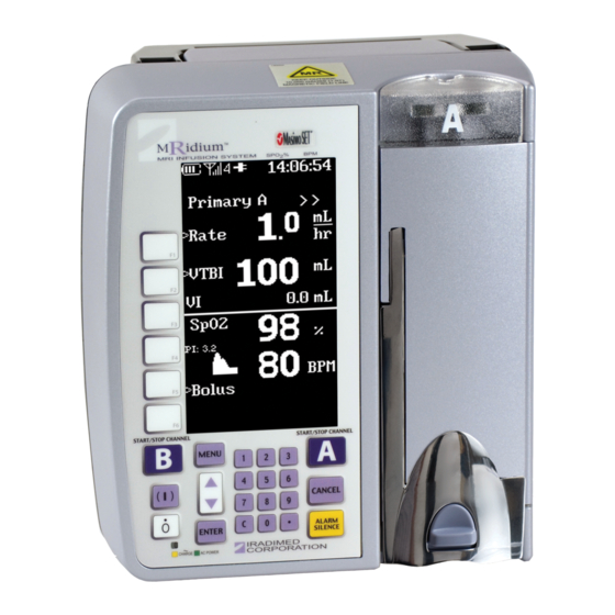
1.1.1 Front of the Pump. See Figure 1-1 for the location of the major components on the front of the pump. Handle. Located on the top of the pump, the handle provides for easy transportation of the pump from location to another. Main Display. -
Page 25: Pump Drive Mechanism
1.1.2 Pump Drive Mechanism. See Figure 1-2 for location of the major components of the infusion system pump drive mechanism. Figure 1-2. Pump Drive Door Open Upper and Lower I.V. Set Snap-In Port. Provides for a secure mounting of the I.V. set for infusion. Linear Peristaltic Pump Drive Mechanism. -
Page 26: Back Of The Pump
1.1.3 Back of the Pump. See Figure 1-3 for the location of the major components on the back of the pump. Handle. Provides for easy transportation of the pump from location to another. Optional Secondary Pump Drive Electrical Connector. Provides for the addition of a Channel B pump mechanism. - Page 27 Fiber Optic Sensor. Use only Iradimed model 1170 Series SpO Fiberoptic Sensors. Battery Compartment. Provides a safe and secure location for the pump’s battery. Use only Iradimed model 1133 Battery Pack. CAUTION: Battery pack is slightly magnetic. Use caution when removing from pump near strong magnetic fields.
-
Page 28: Front Of The Remote Display/Charger
1.1.5 Front of the Remote Display/Charger. See Figure 1-5 for the location of the major components on the front of the 3865 Remote Display/Charger. Antenna. Provides 2.4 GHz bidirectional communication to MRidium 3860 MRI Infusion/Monitor Pump. Main Display. Provides a visual display of all the parameters and features of the pump. -
Page 29: Back Of The Remote Display/Charger
1.1.6 Back of the Remote Display/Charger. See Figure 1-6 for the location of the major components on the back of the 3865 Remote Display/Charger. Audible Speaker. Provides the audible sounds for alarms and alerts. 2.4 GHz Antenna / Connector. Used to connect 2.4 GHz Antenna for wireless communication with the 3860/3860+ MR IV pump. -
Page 30: Front Panel Control Keys
Controls. The MRidium 3860 MRI Infusion/Monitor System is controlled with the use of “soft-touch” control keys. These control keys are located on the front panel of both the Pump and Remote Display. These control keys provide for turning the Pump and Remote Display ON or OFF, starting/stopping Channel’s A and B infusion sequences, accessing and navigating in operational menus, review of data and setups, and for silencing any active alarms that may occur. - Page 31 START/STOP CHANNEL A. Pressing this control key starts, or stops, the Channel A infusion sequence. CANCEL. Pressing the control key returns function to the previous menu or display with no action. Up and Down Arrows. Pressing this control key will increase or decrease the value of the currently selected option.
-
Page 32: Pump Preparation For Use
Pump Preparation for Use. There are several configurations for starting an infusion with the MRidium 3860+ Infusion Pump. These include the following: a. Primary Configuration – Refer to Section 4.0. This mode enables an infusion to be set up with Rate and VTBI only, and is the main screen if the pump has been turned off for more than one (1) hour. -
Page 33: Administration Sets
I.V. site is acceptable under the circumstances in which it is being used. 1.3.1 Administration Sets. Use only Iradimed Corporation approved MRidium 1000 series infusion sets. The use of any other set will cause improper pump operation and will result in inaccurate fluid delivery and risk to the patient. - Page 34 NOTE: Operating parameters (Power, VTBI, etc.) are retained in memory for one (1) hour unless all power is lost (no AC and a depleted battery). A “Settings Lost” message at power up indicates existing operating parameters have been erased, and the system has reverted back to initial default parameter settings. The operator may choose “New Patient”...
-
Page 35: Display
Display. The display screen provides the operator with the information and prompts necessary to operate this pump. See Figure 1-8 and 1-9 for examples of the Primary and secondary displays. In general, the display screen functions as follows: • Highlighting. As the different settings are “scrolled” through (using the Up or Down arrow control key), the selected item will become highlighted to distinguish it from the unselected items. - Page 36 Figure 1-8. Setup Display Screens (Continued) 1-14...
- Page 37 Figure 1-9. Running Screens 1-15...
- Page 38 FIGURE 1-9. Running Screens (Continued) 1-16...
-
Page 39: Informational Display
Additional information (i.e. Dose value, remaining Time, and the Indicator denoting Drug Library card use) can be displayed on the running screens with software revision 3.0.XXXX and higher. 1.4.1 Informational Display.The Informational Display is located at the top of the display screen. - Page 40 STBY Denotes Channel is paused / in standby. Name of Drug Identifies selected Drug from either the Dose Rate Calculator or Dose Error Reduction System (DERS) (Example: Adenosine) Library. DOSE Denotes infusion dose value and corresponding units. RATE Denotes infusion flow rate value in mL/hr. TIME Denotes remaining infusion time until completion with the current infusion parameters.
-
Page 41: User Interface
1.4.6 Special Features Setup Menu. Pressing the MENU button brings up the Special Features Setup Menu (See Figure 1-10) to provide the operator with the ability to set the Dose Rate Calculation, adjust the Alarm Volume, set the KVO Rate, adjust the Occlusion Limit, and Lock Keys and Next Menu if additional options are installed (Refer to Section 4.7 for more information). - Page 42 Cleaning Instructions. Clean Pump and Channel B SideCar and inspect for any physical damage after each use. Perform the following to clean the pump: Unplug power cord from AC outlet before cleaning. Remove Battery Pack from the rear of the Pump. Do not spray fluid directly into any connector.
-
Page 43: Installation
Save all the packing materials, invoice and bill of lading as these may be required to process a claim against the carrier if there is damage from shipment. Contact Iradimed Corporation Customer Service for prompt assistance in resolving shipping problems. -
Page 44: Unpacking 3861 Channel B Sidecar
CAUTION: Use only a non-magnetic I.V. pole designed for proper safe support of the MRidium 3860/3860+ I.V. pumps (Iradimed model 1119 I.V. pole is recommended) Mounting on I.V. Pole. The Pump should be mounted on an MRI-compatible (non-magnetic) I.V. -
Page 45: Determining The Current Iv Pump Software Revision Level
2.7.1 Determining the current IV Pump Software revision level: 1. Turn ON power to the MRidium™ 3860 or, re-start if power is already ON. 2. During the start-up sequence, the current IV Pump Software revision level is displayed in the upper part of the LCD display. The revision level, displayed as either REV: X.X.XXXX, or as “X.X.X”, directly below the words;... -
Page 46: Charging Battery With The Remote
NOTE: With software version 3.0.1307 and higher, the Remote Display/Charger’s communication channel can be linked with an operating 3860+ Pump without pausing the pump. At initial power on of the Remote Display/Charger, the start-up screen provides an option to select the communication channel of the Remote. To change the communication channel perform the following: A.) Turn Remote Display/Charger on. -
Page 47: Language Options
2.10 Language Options. The MRidium System is capable of displaying information in languages other than English. This feature is service selectable, and should only be changed by qualified service personnel, as described in the 1125 Service Manual. 2.11 Product Structure. The MRidium 3860/3860+ MRI Infusion/Monitor system mainly consists of the following:... -
Page 49: Set Preparation For Use
SECTION 3 I.V. SET PREPARATION FOR USE I.V. Set Preparation for Use. Figure 3-1. Free Flow Preventer (Free Flow Preventer is shown in the no flow/closed position). Operation of the Free Flow Preventer. (See Figure 3-1) The Free Flow Preventer is used to stop the flow of the fluid through the infusion set. -
Page 50: Set Priming
• Replace Set according to accepted hospital policies or every six (6) hours maximum. • For I.V. push medication, occlude tubing above injection port. • Contraindicated for most blunt cannula systems. • For unattended medication delivery; only luer-locking Secondary sets and syringes should be attached to the valve. -
Page 51: Extension Set 1058 Priming
NOTE: Do not puncture or add medication through air inlet (See Figure 3-3f). Remove from package, close slide clamp. Remove protective Clear Cap. Attach syringe with fluid to vented Syringe Adapter Fitting at top of I.V. set. Follow accepted hospital procedure. -
Page 52: Set Insertion And Removal
Close FLOW PREVENTER pinch clamp by pulling the black slide clamp outward. Grasp FLOW PREVENTER slide clamp and load pump segment into MRidium pump. Attach distal luer-outlet (blue cap) to pre-existing infusion set's injection port nearest the patient's vascular access device. Open set roller clamp and begin infusion. - Page 53 The tubing will allow gravity flow when the Free Flow Preventer pinch clamp and the roller clamps are in the open position. This provides the ability to infuse fluids/ medications via gravity in an emergency situation. WARNING: Check Free Flow Preventer (black side clamp) is fully pulled outward to the shut off position.
-
Page 55: Primary Configuration
SECTION 4 CONFIGURING THE PUMP FOR USE Primary Configuration. Pressing the control key powers up the pump. Upon power up the pump first runs a Power On Self-Test then displays the message “Powering On” and enters the Primary Pump Setup screen (See Figure 4-1) where the Infusion Rate and Volume to be Infused (VTBI) is set. -
Page 56: Editing The Infusion Program
Use the numeric keys (or the up and down arrow keys) to enter the desired volume to be infused. Observe that the Ready to Start Prompt is displayed. If Ready to Start is not displayed, check the I.V. Set loading and for proper door closure/ latching. -
Page 57: Kvo (Keep Vein Open) - Infusion Complete
4.0.4 KVO (Keep Vein Open) - Infusion Complete. During an infusion, the VTBI value will decrease until the VTBI reaches 0 mL. When the VTBI is 0 mL, the infusion automatically switches to the configured KVO rate, or remains at the programmed primary flow rate, whichever is less. -
Page 58: Dual Channel Infusion
Observe that “Resume Therapy” appears after the self check, if it has been less than one (1) hour since shut down. The display will prompt for the selection of either “New Patient” or “Same Patient.” Press the soft key to select the appropriate choice. (If power has been off for more than one (1) hour, the primary setup screen will display ”New Patient Only”). -
Page 59: Secondary ("Piggyback") Infusion Configuration
Figure 4-2. Dual Infusion Display Secondary (“Piggyback”) Infusion Configuration. NOTE: The Secondary infusion feature is not available when starting an infusion with the dose rate calculator when using the Dose Error Reduction System (DERS) or with Pump software version 3.0.XXXX or higher. A Secondary infusion is the first infusion settings to be implemented in an infusion sequence when more than one infusion is delivered with a single pump channel (either Channel A or B). -
Page 60: Priming A Secondary Administration Set
• The clamp on the secondary set must be opened. If the clamp is not opened, the fluid will be delivered from the primary container. WARNING: The secondary VTBI settings require consideration of such variables as factory overfill, medication additions, etc. Underestimating the volume will cause the remaining Secondary solution to be infused at the Primary rate;... -
Page 61: Programming A Secondary Infusion
NOTE: Iradimed IV Sets 1055,1056, 1057 and 1058 do not have check valves. A third part sterile check valve must be added when configuring a secondary infusion. Figure 4-3. Secondary Infusion Set-up and Programming Screen 4.2.3 Programming a Secondary Infusion. Perform the following to program a secondary infusion in the primary configuration mode: Press the SECONDARY soft key. -
Page 62: Changing Primary Settings During A Secondary Infusion
• When the VTBI = 0 mL, the pump gives an audible alarm and the primary parameters resume and are displayed. WARNING: The clamp on the secondary set must be opened. If the clamp is not opened, the fluid will be delivered from the primary container. The Secondary VTBI must be equal to the volume in the secondary container. -
Page 63: Bolus Delivery
Press CANCEL to return to split running screen without making changes. Figure 4-4. Bolus Setup Displays Bolus Delivery. The Bolus feature is used to deliver a bolus. The operator enters this feature by selecting the Bolus option in the menu on the setup screen or the running screen. -
Page 64: Stopping Bolus Rate Dose
Press the VTBI soft key. Use numeric keys (or the up and down arrow keys) to enter Bolus VTBI value. Press Enter to accept (this starts the Bolus if programmed while the pump is running). If pump was not running, press the START/STOP Channel control key to begin Bolus infusion. -
Page 65: Channel B
Figure 4-5. Attaching Channel B “SideCar” Channel B. (3861 I.V. Pump SideCar ) A second channel may be added to the MRidium pump. Perform substep 4.4.1 to add the Channel B SideCar and substep 4.4.2 to remove the Channel B SideCar. IMPORTANT: 3861 Sidecar can only be used with 3860 or 3860+ Pumps. -
Page 66: Special Features Menu
Sidecar, the pump will verify and match the sidecar software to that of the pump. Interrupting this process will disable the sidecar and require return to Iradimed for repair. Special Features Menu. There are additional features that are accessed by pressing the MENU control key. - Page 67 Figure 4-6. Special Features Menu (continued) 4-13...
-
Page 68: Dose Rate Calculation
Figure 4-7. Dose Rate Calculation Menu 4.5.1 Dose Rate Calculation. The MRidium 3860 infusion pump automatically calculates a Rate based on a Dose amount, Patient Weight, and Concentration of medication. There are three (3) modes of operation: the Basic Dose Rate Calculator, the Dose Rate Calculator with Drug Library, and the Dose Rate Calculator with User- Defined Drug Library.(Refer to chart below and Default Values Table 1 in Appendix A. - Page 69 NOTE: Selecting a different drug name in the Drug Library changes the previous concentration and dose rate values to the default values appropriate for the selected drug. The choice of drug names cannot be modified by the user. 4.5.1.1 Basic Dose Rate Calculator - The Dose Rate Calculator feature is used to calculate the volumetric rate for either Channel A or B, and is accessed using the Menu key.
- Page 70 Observe that the Dose value is highlighted. Use the numeric keys (or the up and down arrow keys) to set the desired Dose value. Press ENTER, or the DOSE soft key. Observe that the units are highlighted. Use the up and down arrow keys to choose the correct unit ordered. NOTE: All available units choices for the dose and concentration settings are provided in Table 3 in Appendix A.
- Page 71 Figure 4-8. Primary Screen with Dose Rate Displayed NOTE: When the Pump is Stopped, “STBY” (Standby) will be displayed to the right of Primary A in place of the pulsing “>>>”. 4.5.1.2 Dose Rate Calculator with Drug Library - The Dose Rate Calculator feature is used to calculate the volumetric rate for either Channel A or B, and is accessed using the Menu key.
- Page 72 Observe that the Dose Rate Calculation Menu (See Figure 4-7) will be displayed with the word "Primary" highlighted. Use the up and down arrow keys to select Primary, Secondary or Bolus. Press ENTER or the DOSE soft key. Observe that the Dose value is highlighted. Use the numeric keys (or the up and down arrow keys) to set the desired Dose value.
- Page 73 4.5.1.3 User Defined Drug Library settings (Internal Drug Library)- The Dose Rate Calculator feature is used to calculate the volumetric rate for either Channel A or Channel B and is accessed using the Menu key. All starting user- defined values in the Drug Library are preset by service personnel, or the user can enter alternate values for any parameter to begin an infusion.
- Page 74 NOTE: In software revision 3.2.9 and higher, the Dose Rate Calculator Bolus feature now defaults the Bolus Dose Units to “mL” so that the initial Bolus setting choices are Volume and Time for any Bolus infusion, rather than the Rate & Volume setting choices.
-
Page 75: Alarm Volume
IMPORTANT: The dose variables (dose and time) displayed on the running screen can vary by very small amounts if the infusion is stopped and re-started without re- starting from the Dose Rate Calculator. When infusing, the original parameter programmed in the Dose Rate Calculator are used. Always verify the Dose Rate Calculator parameters for any subsequent or repeat infusion with the same patient. -
Page 76: Kvo Rate
NOTE: Setting the alarm volume also sets the SpO Pulse Tone volume when it is installed and enabled (3860+ only). 4.5.3 KVO Rate. The MRidium 3860 MRI Infusion Pump will default to a preset KVO (Keep Vein Open) rate (See Figure 4-10) when the Primary infusion VTBI counts down to 0 mL. -
Page 77: Occlusion Limits
4-10a 4-10b Figure 4-10. KVO Rate Screen 4.5.4 Occlusion Limits. The MRidium 3860 MRI Infusion Pump will display an Inlet Occlusion alarm when there is an occlusion between the infusion fluid source and the pump. Patient Occlusion alarm will display when there is an occlusion between the pump and the patient;... -
Page 78: Lock Keys
4.5.5 Lock Keys. This feature allows the user to prevent an accidental key activation. The Lock Key option will not be displayed unless it has been enabled in the Service Mode. Perform the following to activate Key Lock: Press the MENU control key. Press the LOCK KEYS soft key. -
Page 79: Exiting The Special Features Menu
Figure 4-11. Set Comm Channel Displays 4.5.8 Exiting the Special Features Menu. To exit the Special Features Menu, press the MENU or CANCEL control key. The pump will return to the Primary Pump Setup screen where setup of the Primary Pump may be performed. Air Bubble Detection and Reset. - Page 80 4-26...
-
Page 81: Alarms
SECTION 5 ALARMS Alarms. Introduction. User Messages. There are three (3) types of user messages (Alarms, Alerts and User Prompts) displayed on the pump in the users message area (See Figure 5-1). The following is a description of the user messages: Alarm. -
Page 82: Remote Alarms
Remote Alarms. All alarms must be resolved at the pump. Alarms are listed Table 5-1. WARNING: Always Respond to patient at the pump if an alarm occurs. Do not rely on the remote alarm silence function. Patient injury could occur. Figure 5-1. - Page 83 Table 5-1. Alarm, Alert and User Prompt Messages MESSAGE TYPE CAUSE RESOLUTION BAD BATTERY Alert Battery fault has occurred Remove from use. Contact qualified service personnel BATTERY Alert Battery is too low to operate Plug AC Adapter power cord into an DEPLETED Pump much longer.
- Page 84 MESSAGE TYPE CAUSE RESOLUTION History Checksum Prompt Pump detected a memory or Pump has reverted to the default Error power failure. Existing program settings. Press MENU to operating parameters have examine settings, and reenter any been erased. needed infusion setting changes.If message recurs, refer to service personnel for CR2032 coin cell replacement.
- Page 85 MESSAGE TYPE CAUSE RESOLUTION Rate too low Prompt Calculated rate is below the Infusion cannot be started with the minimum rate of the pump existing values. Modify the selected (i.e. 0.1 mL/hr). parameter to allow the infusion to proceed. Review and verify the new infusion parameter(s) before starting the infusion.
- Page 86 MESSAGE TYPE CAUSE RESOLUTION VTBI = KVO Alert VTBI has counted down to Press the appropriate channel's zero. Channel is in KVO mode. START/STOP to stop infusion, then (Audible Only) press ENTER and the VTBI Soft Key to reenter the new VTBI. Change solution container, if necessary.
- Page 87 X ABOVE soft Prompt Selected Channel (A or B) During Primary Infusion limit Programming: The user must value exceeds hospital defined press ENTER to accept the Yes-Enter / DERS high limit. parameter above the High Limit or Cancel-No press CANCEL and enter a value Hospital defined within acceptable limits and proceed The high limit value and...
- Page 88 X BELOW soft Prompt Selected Channel (A or B) During Primary Infusion limit value exceeds hospital defined Programming: The user must DERS lower soft limit. press ENTER to accept the Yes - Enter / parameter below the lower soft Cancel - No Limit or press CANCEL and enter a (DERS only).
-
Page 89: Battery Operation
NOTE: The Battery Pack is sealed such that the batteries can’t be replaced. If the Battery Pack fails or becomes unusable, do not attempt to replace the internal batteries. Replace the Battery Pack. Contact Iradimed Corporation for disposal. Inserting the Battery Pack. Perform the following to insert the Battery Pack into the pump or Remote Display/Charger: Grasp the Battery Pack firmly. -
Page 90: Removing The Battery Pack
Removing the Battery Pack. Press in the Battery Pack latch located on the right side of the installed Pack. Grasp the Pack, and pull it outward from the Pump’s Battery compartment. Another new or charged battery Pack can now be placed into the Pump. -
Page 91: Battery Charge Indicator
Figure 6-3. Battery Test Battery Charge Indicator. The Battery Gauge on the Main Display indicates approximate battery capacity remaining under current operating conditions. It is located in the upper portion of the display and is always visible. Check the remaining battery capacity when starting an infusion. -
Page 92: Battery Power Gauge
Battery Power Gauge. Located at the top left of the informational display, this gauge is in the shape of a battery and provides a visual indication of the capacity status of the battery. When the gauge is “full,” then the battery is at full design capacity, relative to when the battery was new;... -
Page 93: Battery Pack Related Precautions
CAUTION: f placed into storage, to maintain battery life, assure that the battery pack remains charged above 25% (one battery segment is visible) as indicated by the “gas gauge” LED display. 6.11 Battery Pack Related Precautions. The 1133 Battery Pack contains several lithium-polymer cells and an integral safety circuit. -
Page 95: Introduction, Pulse Oximeter, 3860
SpO function on in the appropriate MENU screen. Warnings • USE ONLY Iradimed SpO Fiberoptic Sensors (Sensors containing electrical conductors will cause patient burns). Do not use cables or sensors that contain conductive wires. •... - Page 96 • Use only Iradimed pulse oximeter sensors. These sensors are manufactured to meet the accuracy specifications for Iradimed Corporation’s pulse oximeters. Using other manufacturers’ sensors can result in improper pulse oximeter performance. • As with all medical equipment, carefully route patient cables and connections to reduce the possibility of entanglement or strangulation.
-
Page 97: Installation
Installation. Attach the Iradimed 1170 Fiber Optic SpO sensor (see Section 7.4.1) to the SpO Sensor Connector on the rear panel of the 3860+ IV Pump... -
Page 98: Symbols, Displays, And Controls
Symbols, Displays, and Controls. This section describes the displays, indicators, and controls for %SpO Display. 7.2.1 SpO Symbols. The following symbols are used for the Pulse Oximeter parameter: Adjacent numbers represents the Pulse Oximeter parameter is operating, and are updated every 0.5 seconds. -
Page 99: Displays
7.2.2 Displays. [Refer to Section 1.3 Displays for additional illustration of the SpO2 display details.] Pulse Oximeter (%SpO ) Display The %SpO display is located on the top portion of the 3860 Display (see Figure 7-1), and is identified by the % and SpO symbol. - Page 100 Low HR The Low Heart Rate Alarm Indicator indicates when the pulse rate value is below the Low Heart Rate Alarm setting. When the pulse rate value returns above this value, the Alarm Silence button must be pressed to clear the alarm. No Probe The No Probe Alarm Indicator indicates when no SpO sensor is connected at initial start up, or the sensor has...
-
Page 101: Operator Verification
Menu These keys access control for the upper and lower limits for alarm indications for SpO and pulse rate measurements. When setting up the device, the dedicated SpO MENU display allows the SpO parameter to be enabled, the SpO pulse tone to be enabled/disabled and also allows adjustments of the SpO and Pulse Rate alarm limits, and specific SpO... -
Page 102: Probe Set-Up And Use
7.4.1 Probe Set-up and Use. Model 1170 Adult/Pediatric Fiber Optic Pulse Oximeter Sensor Iradimed Corporation Pulse Oximeter probes, are intended for spot- checking or continuous monitoring of functional oxygen saturation of arterial hemoglobin (SpO ) and pulse rate in a Magnetic Resonance (MR) environment. - Page 103 Set up MRI-SpO Pulse Oximeter with Sensor Grip Connect the MRidium fiberoptic MRI-SpO sensor to the SpO connector located on the rear panel of the 3860+ Pump (See Figure 7.2). Figure 7-2. Connecting the 1170 Fiberoptic Probe Determine the proper size Sensor Grip (Pediatric, Adult, or Large). Follow the insertion guide (See Figure 7.3) to insert the fiberoptic...
- Page 104 Figure 7-3. Applying the 1170 SpO Sensor Secure the position of the fiberoptic MRI-SpO sensor cable in a parallel position to the patient to avoid any bends or kinks in the cable, and prevent any undue pulling of the sensor. When moving the patient and/or the Pump, be careful to handle both the IV line and the MRI-SpO sensor together to avoid entanglement and accidental disconnection...
-
Page 105: Verifying Operation Of The Model 1170 Fiber Optic Sensor
When the infusion has been completed, powering down the Pump, and then re-starting the Pump should clear the SpO Watchdog alarm. If the watchdog alarm cannot be cleared, remove power and contact your distributor or Iradimed Corporation’s Technical Service. 7-11... -
Page 106: Reviewing, Setting, Or Changing Volumes And Alarm Limits
7.6.3 Reviewing, Setting, or Changing Volumes and Alarm Limits. WARNING: For patient safety, ensure that all alarm volumes are set appropriately, and are audible in all situations. Do not cover or otherwise obstruct the speaker opening on the rear of the Pump. Alarm Settings Review. - Page 107 Ensure the sensor is securely finger insertion area. attached to the 3860+ pump. Check the sensor for any visible signs of deterioration contact Iradimed Corporation Technical Service. Sensor bundles are not Ensure the polished glass positioned properly inside the surface of the probe bundles are sensor grip.
- Page 108 If the error persists, disconnect all power, and then reconnect the power and turn the unit back on. If the error still persists, note the error code and contact Iradimed Corporation Technical Service. 7-14...
- Page 109 SpO probe from pump. Parts and Accessories. The following Iradimed Corporation accessories function with the Model 3860+ Pump’s pulse oximeter. Detailed information regarding specified sensor use (patient population, body/tissue, and application) can be found in the respective sensor instructions.
-
Page 110: Spo2 Testing Summary
Testing Summary. accuracy, and low perfusion testing were conducted using the Masimo SET Technology and sensors with Masimo optical sources and receivers. The Iradimed Corporation fiberoptic MRI SpO sensors utilize the same Masimo active optical components. Masimo Rainbow SET technology (using sensors with Masimo optical... -
Page 111: Specifications
7.11 Specifications. Oxygen Saturation Display Range: 0 to 99% SpO2 Pulse Rate Display Range: 30 to 240 pulses per minute (BPM) Accuracy (Arms) FO Sensor ±2% (full scale) over 70-100% Pulse Rate Accuracy (Arms) No Motion ±3 BPM over 30-240 BPM Low Perfusion ±3 BPM over 30-240 BPM a.) ±1 Arms represents approximately 68% of... - Page 112 ® 7.12 The Masimo Set Principles of Operation. ® The Masimo SET MS pulse oximeter is based on three principles: 1. Oxyhemoglobin and deoxyhemoglobin differ in their absorption of red and infrared light (spectrophotometry). 2. The volume of arterial blood in tissue and the light absorbed by the blood changes during the pulse (plethysmography).
- Page 113 The equation for the noise reference is based on the value of R, the value being seeked to determine the SpO . The MS board software sweeps through possible values of R that correspond to SpO values between 1% and 100% and generates an N’...
- Page 114 7-20...
-
Page 115: Dose Error Reduction System
SECTION 8 DOSE ERROR REDUCTION SYSTEM(DERS) PART NUMBER 1145 Dose Error Reduction System. Introduction: The MRidium™ 3860/60+MRI Infusion System may be enhanced to include an optional Dose Error Reduction System (DERS P/N 1145); providing the ability for expansion of the preset internal fixed five name drug library for up to fifty user facility entered drug names, dosing parameters and dose limits. -
Page 116: Ders Features And Definitions
Note: The 'Secondary' infusion feature (piggyback) is not available when the DERS Drug Library is in use. Note: Upon DERS installation users are afforded two programming options; Basic Infusion Protocol (Rate and Volume) and DERS Drug Library. Note: The optional Dose Error Reductions System (DERS) Drug Library Card must be programmed by the hospital/facility Drug Library control personnel prior to installation. -
Page 117: Ders Related Alert And User Prompt Messages
Rate Infusion rate is auto-calculated dependent on the individual Dose, Dosing Units, Concentration, Time and Weight of the selected drug. May not be edited by the user. VTBI An editable starting value for the ‘Volume to be Infused’ within the range of 0.1mL to 999mL. Unit setting is always at ‘mL’. Total volume infused;... -
Page 118: Alert / Prompt - Messages, Type, Cause And Resolution
8.4.1 ALERT / PROMPT - MESSAGES, TYPE, CAUSE AND RESOLUTION. MESSAGE TYPE CAUSE RESOLUTION During Primary Infusion ABOVE HARD limit Selected Channel (A or B) Programming: The primary value exceeds the hospital infusion cannot be started with the defined DERS maximum limit. Hospital defined existing values. - Page 119 BELOW HARD Selected Channel (A or B) During Primary Infusion limit Prompt value exceeds hospital Programming: The primary defined DERS minimum limit. infusion cannot be started with the Hospital defined existing values. Modify the selected drug specific Limits parameter to within the acceptable The minimum limit value and ‘Below Hard Limit’...
-
Page 120: Ders Indicators / Status
Prompt Only adjustments to Dose and To adjust infusion values: Changes Not VTBI are allowed from the · Press ‘Start/Stop’ Channel A Allowed Primary running screen. or Channel B softkey. · Press ‘Cancel’ softkey Adjustments to Concentration · Press ‘Menu’ softkey and Time and are not allowed ·... -
Page 121: Setting Up A Ders Primary Infusion
Note: The following instructions pertain only to the DERS Drug Library and subsequent infusion set-up. (For information on programming a basic infusion via Rate and Volume, please refer to Section 4 page 4-1). SETTING UP A DERS PRIMARY INFUSION. 8.6.1 SETTING UP A DERS PRIMARY INFUSION. Step 1. - Page 122 Step 3. PRESS the ‘ENTER’ softkey when you have located the required drug. NOTE: ‘Primary’ will now be highlighted; indicating you are in the programming screen for a primary infusion. Step 4. PRESS the white softkey corresponding to the ‘Dose’ field.
- Page 123 Using the numerical keypad input the desired ‘DOSE’. Step 5. PRESS ‘ENTER’ (For purposes of illustration, Dose entered is 15) NOTE: If the hospital has defined ‘HARD’ and ‘SOFT’ DOSE limits which are not within the entered range the following prompts will occur.
- Page 124 SOFT • SOFT LIMITS - a single 'BEEP' tone will sound and at LIMIT the TOP of the display screen the message 'ABOVE VIOLATION HARD limit' or 'BELOW hard limit' will alternate with the hospital defined dose limit. User will be prompted to select Yes-Enter/ Cancel-No.
- Page 125 NOTE: Dosing Units / Drug Concentration/ Diluent Volume are automatically entered for the selected drug and cannot be adjusted. NOTE: Required when hospital defined guidelines identify the selected drug as weight-based. If weight is not required then proceed to next step. Step 6.
- Page 126 Step 7. Using the numerical keypad input the patient weight in kilograms and ‘PRESS ‘ENTER’ (for illustration purposes, a weight of 60 is displayed) NOTE: If the hospital has defined ‘HARD’ and ‘SOFT’ WEIGHT limits which are not within the entered range the following prompts will occur.
- Page 127 Step 9. Using the numerical keypad input the infusion ‘Time’ within a range of 0.1 seconds to 99 minutes and ‘PRESS ENTER’. (for illustration purposes a time of 10 is displayed) NOTE: If the hospital has defined ‘HARD’ and ‘SOFT’ TIME limits which are not within the entered range the following prompts will occur.
-
Page 128: Adjusting A Dose Or The Vtbi During An Infusion
Step 11. Using the numerical keypad input the ‘VTBI’ within a range of 0.1 mL to 999 mL and ‘PRESS ENTER’ (for illustration purposes, a VTBI of 100 is displayed) NOTE: VERIFY THAT ALL ENTRIES ARE CORRECT NOTE: Depending on the Channel being programmed;... -
Page 129: Setting Up A Ders Bolus
Step 2. Using the numerical keypad input the desired ‘DOSE’ or ‘VTBI’ PRESS ‘ENTER’ NOTE: If the hospital has defined ‘HARD’ and ‘SOFT’ DOSE limits which are not within the entered range the following prompts will occur. Refer to Section 8.5.1 Page 8-4 for additional information on resolving ‘Limit’... - Page 130 Step 1. PRESS the white softkey corresponding to ‘Bolus’ field. (for illustration purposes, propofol is displayed) NOTE: Pressing the ‘Bolus’ softkey triggers a 10 second window. If no entries are made during this period, the ‘Bolus’ screen defaults back to the Primary Display. Step 2.
- Page 131 Step 3. INPUT the desired ‘DOSE using the numerical keypad. (for illustration purposes, a Dose of 2 is displayed) NOTE: If a hospital pre-defined value is displayed and adjustments are allowed; you may enter a new dose value or proceed to the next step.
- Page 132 Step 4. PRESS the white softkey corresponding to the ‘TIME’ field. NOTE: The RATE and VTBI are now automatically calculated and displayed. Step 5. INPUT the desired ‘Time’ using the numerical keypad. (for illustration purposes a time of 30 is displayed) NOTE: If a hospital pre-defined value is displayed and adjustments are allowed;...
-
Page 133: Repeating A Bolus Dose
Step 6. PRESS ENTER • BOLUS BEGINS Note: Upon completion of the bolus; a ‘beep’ tone sounds and the current primary infusion resumes. Note: ‘Adjust Primary’ allows users to return to the Primary Screen during ‘Bolus’ delivery. 8.6.4 REPEATING A BOLUS DOSE. REPEATING A BOLUS DOSE The values for the last preceding Bolus Dose are stored after the bolus delivery is complete. -
Page 134: Canceling Bolus Delivery
8.6.5 Canceling Bolus Delivery. STEP 1. PRESS Start/Stop ‘A’ or ‘B’ softkey. STEP 2. PRESS Cancel NOTE: Upon pressing the Cancel softkey you will be returned to the Primary running screen. 8-20... -
Page 135: Dual Channel Ders Infusion
8.6.6 DUAL CHANNEL DERS INFUSION. The MRidium™ 3860 pump may be configured to perform simultaneous infusions on both Channel A and B (if equipped with the optional SideCar). DUAL Once both infusions are started, the display screen “splits” to display information for both INFUSION infusion channels. - Page 136 Step 2. PRESS: *Dose Rate Calc A softkey *Dose Rate Calc B softkey *NOTE: Depending on the Channel being programmed. (for illustration purposes Dose Rate Calc. B is selected) NOTE: The ‘Dose Rate B’ screen is now displayed with the first drug in the library highlighted. (for illustration purposes amiodarone is displayed).
-
Page 137: Dual Channel Bolus Delivery
8.6.7 DUAL CHANNEL BOLUS DELIVERY. Step 1. PRESS Menu softkey Step 2. PRESS: Bolus A or Bolus B softkey depending on the Channel you are programming. Step 3 - 6 SETTING UP A DERS BOLUS Section 8.6.3 Page 8-16. 8-23... - Page 138 BOLUS NOTE: During Bolus Delivery; the split display will identify the channel currently in ‘Bolus’ delivery RUNNING mode. DISPLAY Note: Upon completion of the bolus; a ‘beep’ tone sounds and the current primary infusion resumes. Note: Repeating a Bolus; Section 8.6.3 Page 8-16 Note: Canceling a Bolus;...
-
Page 139: Specifications
APPENDIX A SPECIFICATIONS GENERAL SYSTEM REQUIREMENTS General Features Volumetric Infusion Pump for use in the MRI Pump Dive Mechanism Linear Peristaltic Number of Pump Channels User Event Log Non-volatile memory retains each operating step and alarm - up to 5000 entries ELECTRICAL CHARACTERISTICS HI/LO Line Voltage Requirements 100 to 240 VAC +/-10%, 50/60 Hz... - Page 140 PERFORMANCE CHARACTERISTICS Infusion Pump Performance Flow Rate Range - 0 to 100 mL/hr 0.1 to 99.9 mL/hr in 0.1 mL/hr increments Flow Rate Range - > 100 mL/hr 100 to 1400 mL/hr in 1 mL/hr increments Flow Rate Display Range 0.1 to 99.9, 100 to 1400 mL/hr Flow Rate Accuracy within 5% (for 0.1 to 0.9 mL/Hr, within 10%)
- Page 141 PRODUCT STANDARDS REQUIREMENTS STANDARDS COMPLIANCE: IEC 60601-1 STANDARDS COMPLIANCE: IEC 60601-1-2 STANDARDS COMPLIANCE: IEC 60601-2-24 STANDARDS COMPLIANCE: AAMI ID26 STANDARDS COMPLIANCE: UL 60601 STANDARDS COMPLIANCE: ISO 9919...
- Page 142 300.328, no license required Rated RF Output Power +18 dBm (default), 24 dBm (maximum) Service Selectable. Frequency Range 2431.3 to 2474.5 MHz (Iradimed Default) Avoids 802.11 bands 1 and 2 France: 2400 to 2450 MHz with Radio programming selection. Service Selectable.
- Page 143 3861 SIDECAR DUAL PUMP DRIVE MECHANICAL CHARACTERISTICS Dimensions D x W x H 5.5 x 4.5 x 9.5 Inches (14.0 x 11.4 x 24.1 cm) Total Weight 6 LBS (2.7 Kg) Operating Temperature Range to +40 Storage Temperature Range TO +70 Operating Relative Humidity Range 0% to 80% RH, non-condensing Storage Relative Humidity Range...
- Page 144 Air-in-Line Detector Threshold(s) > 100 uL Liquid Source height limits +100 to -50 cm relative to pump center Calibration units of measure mL/hr, mL, Volts, & PSIG MRI PERFORMANCE MRI Magnet Compatibility Same as Pump (0.2 to 3.0 Tesla MRI Systems) MRI Larmor Frequency Interference Same as Pump (No interference at...
- Page 145 Dose Rate Calculator Factory Default Values Table 1 Factory Defaults DRC Default Drug Name Label Values Primary Secondary* Bolus* Drug? Dose 0.0 mcg/kg/min Same as Primary 0.0 mcg/kg/min Conc 1.00 mg/ 1 ml Same as Primary 1.00 mg/ 1 ml 0.0 kg Same as Primary 0.0 kg...
- Page 146 Dose Rate Calculator Custom Protocol Values Worksheet Table 2 Custom Protocol(s) DRC User Selected Custom Drug Name Label Primary Secondary Bolus Custom: Dose Same as Primary Conc Same as Primary Name: Same as Primary Rate Same as Primary Time Same as Primary VTBI Same as Primary Adenosine...
- Page 147 TABLE 3A STANDARD USER SETTING RANGES AND DEFAULTS Characteristic Specification Range Initial Start-Up (Factory Default) Value Primary Flow Rate Range - 0 to 100 0.1 to 99.9 mL/hr in 0.1 mL/hr 1 mL/hr mL/hr increments Primary Flow Rate Range - > 100 mL/ 100 to 1400 mL/hr in 1 mL/hr 1 mL/hr increments...
- Page 148 Additional Dose Rate Calculator Settings and Ranges (for use with Dose Rate Calculator and Dose Error Reduction System (DERS)) Table 3B Units Value Minimum Default Maximum Notes Dose mcg/kg/min 0.01 9,999 mg/kg/min 0.01 9,999 mcg/kg/hr 0.01 9,999 mg/kg/hr 0.01 9,999 mcg/kg 0.01 9,999...
- Page 149 Infusion Set Specifications I.V. ADMINISTRATION SETS General Specifications IV Set Materials used PVC Tubing (No Latex or DEHP) Integral Free Flow Protection Custom flow preventer incorporated into each set. Fluid free-flow can't occur without mechanically opening the flow preventer. Air-Trapping Feature Air-Trapping "Y"...
- Page 150 A-12...
-
Page 151: Repair
8022 from outside the U.S.(during normal business hours EST), or by E-mail at techsupport@iradimed.com. Iradimed Corporation Technical Service will advise you of the corrective action required. If you are advised to return the pump to Iradimed Corporation for repair, please do the following: Obtain a Return Authorization Number. -
Page 153: Appendix C: Warranty
This warranty will become null and void if product has been repaired other than by Iradimed Corporation, or its authorized representative, or if the product has been subject to misuse, accident, negligence, or abuse. - Page 154 Iradimed and restored to full operational specification as where applicable at the time of original manufacture. Any Maintenance Extension will become null and void if product has been repaired other than by Iradimed Corporation, or its authorized representative, or if the product has been subject to misuse, accident, negligence or abuse.
-
Page 155: Appendix Dmanufacturers Technical Declaration
APPENDIX D MANUFACTURERS TECHNICAL DECLARATION... - Page 156 EMC Information Tables as required by EN 60601-1-2:2000 Clause 6 In accordance with EN 60601-1-2:2000 Medical Electrical Equipment – Part 1-2: General requirements for safety – Collateral standard: Electromagnetic Compatibility – Requirements and tests 1. “Medical Electrical Equipment needs special precautions regarding EMC and needs to be installed and put into service according to the EMC information provided in the Accompanying Documents”...
- Page 157 MRIdium 3860 System Table 202—Guidance and manufacturer’s declaration— electromagnetic immunity—for all EQUIPMENT and SYSTEMS Guidance and manufacturer’s declaration—electromagnetic immunity The MRidium 3860 System is intended for use in the electromagnetic environment customer or the user of the MRidium 3860 System should assure that it is used in such an environment. Immunity test IEC 60601 test Compliance level...
- Page 158 Table 203—Guidance and manufacturer’s declaration— electromagnetic immunity—for LIFE-SUPPORTING EQUIPMENT and SYSTEMS Guidance and manufacturer’s declaration—electromagnetic immunity The MRidium 3860 System is intended for use in the electromagnetic environment customer or the user of the MRidium 3860 System should assure that it is used in such an environment. Immunity test IEC 60601 test Compliance level...
- Page 159 MRIdium 3860 System Table 205—Recommended separation distances between portable and mobile RF communications equipment and the EQUIPMENT or SYSTEM—for LIFE-SUPPORTING EQUIPMENT and SYSTEMS Recommended separation distances between portable and mobile RF communications equipment and the MRidium 3860 System The MRidium 3860 System is intended for use in an electromagnetic environment in which radiated RF disturbances are controlled.
- Page 163 comunicazioni.it...
- Page 164 D-10...
-
Page 165: Appendix E: Accessories
APPENDIX E IV SETS AND ACCESSORIES nfusion Sets: 1055-50 Bypass Infusion Set (carton of 50) 1056-50 Infusion Set (carton of 50) 1057-50 Syringe Adapter Set (carton of 50) 1058-50 Extension Set (carton of 50) Accessories: 1119 - MRidium MRI IV Pole (Non-Magnetic (non-ferrous) I.V. Pole, 1.25 in. -
Page 167: Appendix Ftroubleshooting
APPENDIX F TROUBLESHOOTING Problem Possible Cause Solution Unit not turned on. Turn on unit by pressing 1 (On) control key. No AC power/battery Plug power cord into pump and depleted. AC power source or replace battery pack with charged Pump won’t turn battery. - Page 168 Problem Possible Cause Solution Fluid side of Set is not Inspect for damage or leaks, and properly connected. replace if necessary. Fluid Leaking from Administration Damaged Set is leaking. Examine Set to locate leak. Set. Disconnect Set from the patient. Replace and resume infusion.
- Page 169 Problem Possible Cause Solution Pump turned off for Train appropriate personnel that longer than one (1) hour turning off the pump for more between uses. than one (1) hour resets pump settings. Pump settings are Pump settings changed Double check key sequence for restored to accidentally.
- Page 170 Problem Possible Cause Solution Air is present in the Examine Set to locate air bubble. Administration Set. Disconnect Set from the patient. Purge Air in Line. Re-prime line and resume infusion. Administration Set Roller Open Roller Clamp on clamp is closed. Administration Set.
- Page 171 2 Pumps on the same channel. MRI Magnet Room Refer to qualified service shielding reduces radio personnel. Radio transmission signal strength to prevent power can be increased (within communication. limits) by service personnel to accommodate most MRI magnet rooms. Contact Iradimed Corporation for additional information.
- Page 173 Dry all mounting assemblies thoroughly after cleaning. CAUTION: Iradimed Corporation makes no claims regarding the efficacy of the listed chemicals or processes as a means for controlling infection. Consult your hospital's infection control officer or epidemiologist. To clean or sterilize mounted instruments or accessory equipment, refer to the specific instructions delivered with those products.
- Page 174 IV POLE CONFIGURATION 1 Iradimed Corporation 1119 Telescoping MR IV Pole Installation Guide REF 1179 1. General Information: These instructions for use should enable you to use the IV Pole safely and properly. Please read through these instructions carefully before using the IV Pole for the first time.
- Page 175 · Federal law in the USA restricts this device to sale by or on the order of a physician. · For safe operation, use only Iradimed Corporation recommended MRI- compatible or MRI-safe accessories. · Always secure the IV Pole ·...
- Page 176 Dry all mounting assemblies thoroughly after cleaning. CAUTION: Iradimed Corporation makes no claims regarding the efficacy of the listed chemicals or processes as a means for controlling infection. Consult your hospital's infection control officer or epidemiologist.
- Page 177 Any repairs should be done by authorized personnel with original equipment only. 7. Specifications: MRI Compatibility: MRI Safe with MRI Scanner up to 3 Tesla (outside MRI Bore). Dimensions and Weight: Telescoping IV Pole; Base Width: 72 cm (28 in.) Base Wheel Profile: 5 Casters in a star-configuration Wheel Diameter:...
- Page 178 ASSEMB L Y DI A GRAM HM107 IV POLE, NON-MAGNETIC HM106 CAST LEG HM106 CAST LEG HM105 HM104 HM116 HM117 HM111 USE M10 CAP SCREW WITH L OCKING W ASHER T O ASSEMBLE E A CH LEG T O BASE. A L TERN A TE BRAKE AND NON-BRAKE CASTERS.
- Page 180 IV POLE CONFIGURATION 2 1119 I.V. POLE ASSEMBLIES AND PARTS DESCRIPTIONS...
- Page 181 ▪ Federal law in the USA restricts this device to sale by or on the order of a physician. ▪ For safe operation, use only Iradimed Corporation recommended MRI-compatible or MRI-safe accessories. ▪ Always secure the IV Pole wheel locks after positioning within the MRI Magnet Room.
- Page 182 1119 Assembly Instruction Rev. C 010308 Assembling the Roll Stand (Post to Base) 1. Insert Lower IV Pole in Base and lay assembly on its side for access to bottom of Base (not shown). 2. Using a 1/2'' [13 mm] wrench, fasten Post to Base with one (1) 5/16-18 x 2'' HHCS, 5/16 split lock washer, and 5/16'' flat washer.
- Page 183 1119 Assembly Instruction Rev. C 010308 Attaching Upper IV Pole to Lower Pole 1. Screw Upper Pole clockwise (CW) onto Lower Pole. Tighten as much as possible by hand. 2. Using the 3/32'' hex wrench provided, tighten the set screw in the Upper Pole. Screw Upper Pole CW onto Lower Pole Tighten Set Screw...
- Page 184 1119 Assembly Instruction Rev. C 010308 Routine Maintenance Periodically check all mounting hardware. Tighten as necessary for optimal operation. Cleaning the Mounting Assembly 1. The mounting assembly may be cleaned with most mild, non-abrasive solutions commonly used in the hospital environment (e.g.
- Page 185 IV POLE CONFIGURATION 3 1119 I.V. POLE ASSEMBLIES AND PARTS DESCRIPTIONS NOTE: The following tools are required for the assembly of this IV Pole: Small Screws 1/8” HEX Big Screws 3/16” HEX Bolthead 1/2” Wrench G-13...
- Page 186 G-14...
- Page 187 G-15...
- Page 188 G-16...
-
Page 189: Appendix Htrumpet And Start Up Curves
APPENDIX H TRUMPET AND START UP CURVES In this Pump, as with all infusion systems, the actions of the pumping mechanism can cause short term fluctuations in rate accuracy. The graphs below (Figure G-1 through G-14) show typical performance of the system with its specific infusion sets. For those not familiar with trumpet curves, the “0”... - Page 190 Effects of Negative Solution Container Heights With a negative head height of -0.5 meters, the MRidium 3860 Infusion System exhibits a long–term accuracy offset of approximately -2.0% from mean values. No significant change in short–term variations result under negative head height conditions.
- Page 191 Figure H-1. Figure H-2.
- Page 192 Figure H-3. Figure H-4.
- Page 193 Figure H-5. Figure H-6.
- Page 194 Figure H-7. Figure H-8.
- Page 195 Figure H-9. Figure H-10.
- Page 196 Figure H-11. Figure H-12.
- Page 197 Figure H-13. Figure H-14.
- Page 198 Figure H-15. Figure H-16. H-10...
- Page 199 Figure H-17. Figure H-18. H-11...
- Page 200 Figure H-19. Figure H-20. H-12...
- Page 201 H-13...
- Page 202 H-14...
-
Page 203: Appendix I: 1145 Dose Error Reduction System
APPENDIX I 1145 Dose Error Reduction System (DERS) Software Update Kit:... - Page 204 1145 Dose Error Reduction System (DERS) Software Update Kit: MRidium™ 3860+ IV Pump Software Update Procedure A. To determine the current IV Pump Software revision level: Turn ON power to the MRidium™ 3860+ or, re-start if power is already ON. During the start-up sequence, the current IV Pump Software revision level is displayed in the upper part of the LCD display.
- Page 205 WARNING: Be sure to remove the AM04 DERS MRidium™ IV Pump Software Update Card when the software has updated, otherwise it will attempt to reload on the next reboot or start-up. NOTE: If a Remote Display 3865 is being used with the MRidium™ 3860+, its software must also be updated at the same time using the Software Update Card described previously.
- Page 206 D. To add the DERS Library programming card: 1. Turn OFF power to the MRidium™ 3860+. 2. Remove the small poly bag from the 1145 update kit which contains the Black Aluminum SD Card retainer clip and the #4 screw. This part will be used as a safety guard once the programming card is in place.
- Page 207 NOTES...
- Page 212 I-10...
Need help?
Do you have a question about the MRIDIUM 3860+ and is the answer not in the manual?
Questions and answers
What types of cleaners may be used? Can cavi wipes and/or bleach wipes be used?