Table of Contents
Advertisement
Advertisement
Table of Contents

Related Manuals for Flavel Jazz

Summary of Contents for Flavel Jazz
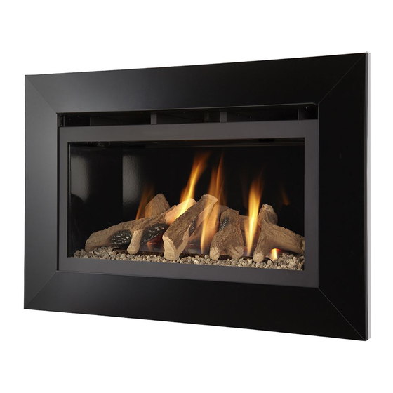
- Page 1 Jazz & Jazz “Impact” DECORATIVE LOG EFFECT ROOM HEATER Installation and Maintenance Instructions Hand these instructions to the user Model No. FJZL**RN is for use on Natural Gas (G20) at a supply pressure of 20 mbar in G.B. / I.E.
-
Page 2: Table Of Contents
Unpacking the combustion chamber Preparing the combustion chamber opening (In studded wall) Preparing the combustion chamber opening (In chimney breast) Removal and re-fitting of the Jazz Impact Fascia Removal and re-fitting of the Jazz Standard Fascia Installation of the gas supply Removal &... -
Page 3: Information And Requirements
115mm to Flat Face of Flue Termination (fitting wthout liner) 630 mm 170mm 480mm 375mm 460mm 295 mm Flue Spigot Mounting 775mm Jazz Impact Frame 810mm Jazz Standard 295mm 855 mm Jazz Impact 765mm Jazz Standard... -
Page 4: Conditions Of Installation
INSTALLATION REQUIREMENTS CONDITIONS OF INSTALLATION It is the law that all gas appliances are installed only by a GAS SAFE Registered Installer, in accordance with these installation instructions and the Gas Safety (Installation and Use) Regulations 1998 as amended. Failure to install appliances correctly could lead to prosecution. -
Page 5: Shelf Position
SHELF POSITION The fire may be fitted below a combustible shelf providing there is a minimum distance of 300mm above the top of the fire and the shelf does not project more than 150mm. If the shelf overhangs more than 150mm the distance between the fire and the shelf must be increased by 15mm for every 25mm of additional overhang over 150mm. -
Page 6: Installation Of Fire
SECTION 2 INSTALLATION OF FIRE UNPACKING THE COMBUSTION CHAMBER Carefully lift the combustion chamber out of the carton. Remove the loose item packaging carefully from the pack. Check the contents as listed :- DO NOT UNDER ANY CIRCUMSTANCES USE THIS APPLIANCE IF THE GLASS PANEL IS BROKEN OR NOT SECURELY FIXED TO THE FIREBOX. -
Page 7: Preparing The Combustion Chamber Opening (In Studded Wall)
PREPARATION OF THE COMBUSTION CHAMBER OPENING (INTO STUDDED WALL) USING A 125MM FLUE LINER. All combustible parts of the studwork must be set at the distances as shown below in Fig. 3 & 4. Please ensure the installation complies with document IGE / UP7, Gas Installations in Timber Framed Buildings. -
Page 8: Preparing The Combustion Chamber Opening (In Chimney Breast)
PREPARATION OF THE COMBUSTION CHAMBER OPENING (INTO EXISTING CHIMNEY BREAST) An opening should be constructed to the following dimensions in the existing chimney breast. See fig. 5 below Fig. 5 Lintle must project 150mm either side of the Minimum Width 630mm opening if Maximum Width 640mm cutting into an... - Page 9 Fig. 6 The Interactive Zone - Openings, beams or joists within this area need to be assessed. 400mm interactive area Load triangle - No beam or opening permissible within this area 600mm load triangle Lintel e.g. 750mm x 75mm Proposed Opening in Chimney Breast If fitting without a flue liner, ensure a minimum clearance of 50mm is available around the outlet faces of the flue termination to any surface within the chimney...
-
Page 10: Removal And Re-Fitting Of The Jazz Impact Fascia
REMOVAL AND RE-FITTING OF THE JAZZ “IMPACT” FASCIA TO THE PRODUCT. The Jazz “Impact” Fascia is fitted to the product via hooking the fascia onto the mounting flange slots at the top and securing via magnets at the bottom. See Fig. 7 below. -
Page 11: Removal And Re-Fitting Of The Jazz Standard Fascia
REMOVAL AND RE-FITTING OF THE JAZZ STANDARD FASCIA TO THE PRODUCT. The Jazz standard fascia is fitted to the product via hooking the fascia onto the mounting flange slots at the top. See Fig. 9 below. Fig. 9 Hook slots on... -
Page 12: Installation Of The Gas Supply
INSTALLATION OF THE GAS SUPPLY (INTO STUDDED WALL OR EXISTING CHIMNEY BREAST) Before installing the combustion chamber, decide from which side or if a rear connection to the gas supply is required. Plan the pipe run to enter the below the firebox from the left, right or rear and connect to the inlet elbow. -
Page 13: Removal & Re-Fitting Of The Glass Frame
REMOVING / RE-FITTING THE GLASS FRAME ASSEMBLY The glass frame is held in position by hooking the top flange over the combustion chamber opening at the top as shown in Fig. 14 below. Fig. 14 Glass Frame Assembly locates over lip on top of combustion chamber lid, and drops onto flange as shown. -
Page 14: Connection Of The Flue Liner And Fitting Of The Draught Diverter
CONNECTION OF THE FLEXIBLE FLUE LINER (IF FITTED) If fitting with a 5” / 125mm flue liner, ensure the liner has been connected and securely fixed at the top of the chimney in accordance with the manufacturers instructions. Feed or align the flexible flue liner through the hole in the top of the combustion chamber The flexible liner should be then fitted to the 5”... - Page 15 Re-fit the draught diverter and secure with the five off M4 screws as shown below in Fig. 18 Fig. 18 Refit 5 off M4 Screws IMPORTANT NOTE : ENSURE THAT THE DRAUGHT DIVERTER HAS THE 3 OFF SCREWS FITTED AT THE FRONT EDGE NEAREST THE GLASS PANEL. THIS WILL ENSURE THAT THE DRAUGHT DIVERTER IS FITTED IN THE CORRECT ORIENTATION IN THE COMBUSTION CHAMBER.
-
Page 16: Fitting Of The Flue Terminal And Fitting Of The Draught Diverter
CONNECTION OF THE FLUE TERMINAL AND RE-FITTING THE DRAUGHT DIVERTER. If fitting without a flue liner, into a chimney that is has had it’s soundness assured by testing, and is less than 10 metres in height on an external wall or 12 metres on an internal wall, then the appliance should be re-fitted with the flue terminal as supplied. -
Page 17: Fitting The Fuel Bed Logset
SECTION 3 INSTALLATION OF FIRE FITTING THE FUEL-BED LOGSET The gravel material should then be first layed around the base of the combustion chamber as shown below in Fig. 21, leaving the rear section as shown to allow the fitting of Log “A” Fig. - Page 18 Fit Log “B” into position on right hand side of the fuel-bed base log “A”as shown below in Fig. 23, using the groove in Log “A” as a guide for placement, and locate the in slot the fork of the log into the upturn in the base plate.
- Page 19 Fit Log “D” into position on left hand side of the fuel-bed base log “A”as shown below in Fig. 25, using the groove in Log “A” as a guide for placement, and locate the slot in the log into the upturn in the base plate.
-
Page 20: Making The Gas Connection & Checking For Gas Tightness
Warning : Use only the logs supplied with the fire. When replacing the logs remove the old logs and discard them. Fit a complete set of logs of the correct type. Do not fit additional logs or any logs other than a genuine replacement set. -
Page 21: Lighting The Appliance
LIGHTING THE APPLIANCE IMPORTANT : IF THE BURNER IS EXTINGUISHED FOR ANY REASON YOU MUST ENSURE THAT YOU WAIT A FULL FIVE MINUTES BEFORE ATTEMPTING TO RE-LIGHT THE FIRE. Fig. 27 Pilot Control Main Burner Knob Knob Locate the control valve on the appliance, it is situated below the combustion chamber in the centre. - Page 22 To adjust the heat input via the remote handset :- Press the “up” button to light the main burner and adjust the heat input to the maximum setting. (5.5kW heat input). If you press and hold the “down” button it will reduce the heat input to the minimum (3.0kW heat input) setting, if you keep the button depressed it will turn the main burner off at this point a clicking noise will be heard from the motor.
- Page 23 AFTER THE PILOT FLAME HAS BEEN EXTINGUISHED, IF YOU WISH TO RE-LIGHT THE APPLIANCE YOU MUST WAIT AT LEAST THREE MINUTES BEFORE TRYING TO RE-LIGHT THE APPLIANCE. Finally, hand the Installation and Maintenance Instructions and the Users Instructions over to the customer and explain the operation of the fire.
-
Page 24: Checking For Clearance Of Combustion Products
CHECKING FOR CLEARANCE OF COMBUSTION PRODUCTS Close all doors and windows in the room. Light the fire and allow to run for approximately 5 minutes on high position. After approximately 5 minutes hold a smoke match just inside and below the centre of the lower front edge of the top of the fire as shown in Fig. -
Page 25: Maintenance
Servicing Notes Servicing should be carried out annually by a competent person such as a GAS SAFE registered engineer. It is a condition of Flavel Fires guarantee schemes that this is carried out by a competent person i.e a GAS SAFE registered Engineer in accordance with these servicing notes. -
Page 26: Removal Of The Ultrasonic Reciever
and disconnect the thermocouple from the pilot assembly. 4.2.5 Remove the 2 off fixing screws which hold the valve mounting plate to its mounting bracket and lift the valve and its mounting plate away from the combustion chamber. 4.2.6 Swap the valve mounting plate onto the new valve by unscrewing the two M5 nuts and bolts holding it in position . -
Page 27: Removal / Replacement Of Batteries In The Ultrasonic Receiver
Parts Shortlist Graphite Rear Fibre Board (Jazz Impact & Jazz Black) B-101480 Graphite Left Hand Fibre Board (Jazz Impact & Jazz Black) B-101490 Graphite Right Hand Fibre Board (Jazz Impact & Jazz Black) B-101500 Cream Rear Fibre Board (Jazz Cream) - Page 28 Due to our policy of continual improvement and development the exact accuracy of illustrations and descriptions contained in this book cannot be guaranteed Part No. B-134940 Issue 1 BFM Europe Ltd. Trentham Lakes Stoke-on-Trent Staffordshire ST4 4TJ www.bfm-europe.com Telephone - General Enquiries : (01782) 339000 Telephone - Service : (0844) 7700169...
Need help?
Do you have a question about the Jazz and is the answer not in the manual?
Questions and answers