Table of Contents
Advertisement
Quick Links
Advertisement
Table of Contents
Troubleshooting

Related Manuals for Yamaha FZ6-N


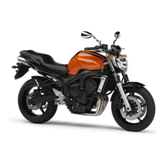
Summary of Contents for Yamaha FZ6-N
- Page 1 OWNER’S MANUAL FZ6-N 1B3-28199-E1...
- Page 2 EAU26941 DECLARATION of CONFORMITY Company: MORIC CO., LTD. Address: 1450-6 Mori Mori-Machi Shuchi-gun Shizuoka 437-0292 Japan Hereby declare that the product: Kind of equipment: IMMOBILIZER Type-designation: 5SL-00, 5VS-00, 5VX-00, 3HT-00, 5UX-00, 5UX-10, 5KS-00 and 5KS-10 is in compliance with following norm(s) or documents: R&TTE Directive(1999/5/EC) EN300 330-2 v1.1.1(2001-6), EN60950(2000) Two or Three-Wheel Motor Vehicles Directive(97/24/EC: Chapter 8, EMC)
- Page 3 Yamaha a reputation for dependability. Please take the time to read this manual thoroughly, so as to enjoy all advantages of your FZ6-N. The owner’s manual does not only instruct you in how to operate, inspect and maintain your motorcycle, but also in how to safeguard yourself and oth- ers from trouble and injury.
-
Page 4: Important Manual Information
This manual should be considered a permanent part of this motorcycle and should remain with it even if the motorcycle is subsequently sold. Yamaha continually seeks advancements in product design and quality. Therefore, while this manual contains the most current product information available at the time of printing, there may be minor discrepancies between your motorcycle and this manual. - Page 5 IMPORTANT MANUAL INFORMATION EAU10200 FZ6-N OWNER’S MANUAL ©2004 by Yamaha Motor Co., Ltd. 1st edition, June 2004 All rights reserved. Any reprinting or unauthorized use without the written permission of Yamaha Motor Co., Ltd. is expressly prohibited. Printed in Japan.
-
Page 6: Table Of Contents
TABLE OF CONTENTS SAFETY INFORMATION ....1-1 PRE-OPERATION CHECKS ..... 4-1 Adjusting the clutch lever free Pre-operation check list ....4-2 play ........... 6-16 DESCRIPTION ........2-1 Adjusting the rear brake light Left view ..........2-1 OPERATION AND IMPORTANT switch ........6-17 Right view ........2-2 RIDING POINTS......... - Page 7 TABLE OF CONTENTS Replacing a turn signal light bulb ...........6-30 Replacing the license plate light bulb ...........6-30 Replacing an auxiliary light bulb ...6-31 Supporting the motorcycle ....6-31 Front wheel ........6-32 Rear wheel ........6-33 Troubleshooting ......6-35 Troubleshooting charts ....6-36 MOTORCYCLE CARE AND STORAGE ..........7-1 Care ..........7-1 Storage ...........7-3...
-
Page 8: Safety Information
SAFETY INFORMATION EAU10281 AND/OR WHEN MADE NECES- • Ride where other motorists can SARY BY MECHANICAL CONDI- see you. Avoid riding in another MOTORCYCLES SINGLE TIONS. motorist’s blind spot. TRACK VEHICLES. THEIR SAFE USE Many accidents involve inexperi- AND OPERATION ARE DEPENDENT Safe riding enced operators. - Page 9 Modifications made to this motorcycle other motorists can see you. the single most critical factor in the pre- not approved by Yamaha, or the re- The posture of the operator and vention or reduction of head injuries. moval of original equipment, may ren- passenger is important for proper Always wear an approved helmet.
- Page 10 Maximum load: been specifically designed for use on create instability due to improper 196 kg (432 lb) this motorcycle. Since Yamaha cannot weight distribution or aerody- test all other accessories that may be namic changes. If accessories When loading within this weight limit,...
- Page 11 SAFETY INFORMATION tor and may limit control ability, Always turn the engine off before or clothing, immediately wash the therefore, such accessories are leaving the motorcycle unattended affected area with soap and water not recommended. and remove the key from the main and change your clothes.
-
Page 12: Description
DESCRIPTION EAU10410 Left view 1. Main fuse (page 6-27) 9. Engine oil drain bolt (page 6-6) 2. Battery (page 6-26) 10.Engine oil filter cartridge (page 6-6) 3. Air filter element (page 6-11) 4. Idle adjusting screw (page 6-12) 5. Shock absorber assembly spring preload adjusting ring (page 3-15) 6. -
Page 13: Right View
DESCRIPTION EAU10420 Right view 1. Fuse box (page 6-27) 2. Rear brake fluid reservoir (page 6-18) 3. Coolant reservoir cap (page 6-9) 4. Engine oil filler cap (page 6-6) 5. Front brake fluid reservoir (page 6-18) 6. Dipstick (page 6-6) 7. -
Page 14: Controls And Instruments
DESCRIPTION EAU10430 Controls and instruments 1. Clutch lever (page 3-10) 2. Left handlebar switches (page 3-8) 3. LCD tachometer (page 3-5) 4. Multi-function display (page 3-5) 5. Right handlebar switches (page 3-8) 6. Brake lever (page 3-10) 7. Throttle grip (page 6-13) 8. -
Page 15: Instrument And Control Functions
Do not expose any key to exces- a Yamaha dealer to have them re-reg- sively high temperatures. istered. Do not use the key with the red Do not place any key close to bow for driving. -
Page 16: Main Switch/Steering Lock
INSTRUMENT AND CONTROL FUNCTIONS EAU10471 EAU10560 To lock the steering Main switch/steering lock All electrical circuits are supplied with power; the meter lighting, taillight, li- cense plate light and auxiliary light come on, and the engine can be start- ed. The key cannot be removed. NOTE: The headlight comes on automatically when the engine is started and stays on... -
Page 17: Indicator And Warning Lights
INSTRUMENT AND CONTROL FUNCTIONS To unlock the steering EAU34340 EAU11002 (Parking) Indicator and warning lights The steering is locked, and the taillight, license plate light and auxiliary light are on. The hazard light and turn signal lights can be turned on, but all other electrical systems are off. - Page 18 When this occurs, can be checked by turning the key to lizer system is still enabled. have a Yamaha dealer check the self- “ON”. diagnosis system. (See page 3-5 for an NOTE:...
-
Page 19: Lcd Tachometer
INSTRUMENT AND CONTROL FUNCTIONS EAU32922 ECA10031 EAU32976 LCD tachometer Multi-function display CAUTION: EWA12311 Do not operate the engine in the ta- WARNING chometer red zone. Be sure to stop the vehicle before Red zone: 14000 r/min and above making any setting changes to the multi-function display. - Page 20 INSTRUMENT AND CONTROL FUNCTIONS two tachometers, one LCD and Odometer, tripmeter and digital ta- itself automatically and the display will one digital (which show engine chometer modes return to the prior mode after refueling r/min) Pushing the “SELECT” button switches and traveling 5 km (3 mi).
- Page 21 (e.g., flash. If this occurs, have a Yamaha 12, 13, 14). dealer check the electrical circuit. This model is also equipped with a self- 1.
-
Page 22: Anti-Theft Alarm (Optional)
” Yamaha dealer and have the stan- dard keys re-registered. If the multi-function display indicates any error code, note the code number, and then have a Yamaha dealer check the vehicle. ECA11590 CAUTION: If the display indicates an error code, the vehicle should be checked as soon as possible in order to avoid engine damage. - Page 23 INSTRUMENT AND CONTROL FUNCTIONS Right position. To cancel the turn signal EAU12731 Hazard switch “ ” lights, push the switch in after it has re- With the key in the “ON” or “ ” posi- turned to the center position. tion, use this switch to turn on the haz- ard light (simultaneous flashing of all EAU12500...
-
Page 24: Clutch Lever
INSTRUMENT AND CONTROL FUNCTIONS EAU12820 EAU12870 EAU26822 Clutch lever Shift pedal Brake lever The brake lever is located at the right handlebar grip. To apply the front brake, pull the lever toward the handle- bar grip. 1. Clutch lever 1. Shift pedal The clutch lever is located at the left The shift pedal is located on the left handlebar grip. -
Page 25: Brake Pedal
INSTRUMENT AND CONTROL FUNCTIONS EAU12941 EAU13070 Brake pedal Fuel tank cap NOTE: The fuel tank cap cannot be closed un- less the key is in the lock. In addition, the key cannot be removed if the cap is not properly closed and locked. EWA11090 WARNING Make sure that the fuel tank cap is... -
Page 26: Fuel
Your Yamaha engine has been de- signed to use regular unleaded gaso- line with a research octane number of 91 or higher. If knocking (or pinging) oc-... -
Page 27: Fuel Tank Breather Hose
INSTRUMENT AND CONTROL FUNCTIONS EAU13410 EAU13430 EAU32980 Fuel tank breather hose Catalytic converter Seat This model is equipped with a catalytic converter in the exhaust chamber. To remove the seat 1. Insert the key into the seat lock, EWA10860 WARNING and then turn it counterclockwise. -
Page 28: Storage Compartment
3. Strap 3. Remove the key. This storage compartment is designed NOTE: to hold a genuine Yamaha U-LOCK. Make sure that the seat is properly se- (Other locks may not fit.) When placing cured before riding. a U-LOCK in the storage compartment, securely fasten it with the straps. -
Page 29: Adjusting The Shock Absorber Assembly
1. Spring preload adjusting ring Spring preload setting: formance. 2. Special wrench Minimum (soft): Always have a Yamaha dealer 3. Position indicator service the shock absorber. Standard: This shock absorber assembly is equipped with a spring preload adjust- Maximum (hard): ing ring. -
Page 30: Sidestand
INSTRUMENT AND CONTROL FUNCTIONS EAU15300 below and have a Yamaha dealer re- EAU15311 Sidestand Ignition circuit cut-off system pair it if it does not function proper- The sidestand is located on the left side The ignition circuit cut-off system (com- of the frame. - Page 31 5. Push the start switch. Does the engine start? The neutral switch may be defective. The motorcycle should not be ridden until checked by a Yamaha dealer. With the engine still running: 6. Move the sidestand up. 7. Keep the clutch lever pulled.
-
Page 32: Pre-Operation Checks
PRE-OPERATION CHECKS EAU15591 The condition of a vehicle is the owner’s responsibility. Vital components can start to deteriorate quickly and unexpectedly, even if the vehicle remains unused (for example, as a result of exposure to the elements). Any damage, fluid leakage or loss of tire air pressure could have serious consequences. -
Page 33: Pre-Operation Check List
• If necessary, add recommended coolant to specified level. • Check cooling system for leakage. • Check operation. • If soft or spongy, have Yamaha dealer bleed hydraulic system. • Check brake pads for wear. Front brake • Replace if necessary. - Page 34 • Make sure that operation is smooth. • Check cable free play. Throttle grip 6-13, 6-22 • If necessary, have Yamaha dealer adjust cable free play and lubricate cable and grip housing. • Make sure that operation is smooth. Control cables 6-21 •...
-
Page 35: Operation And Important Riding Points
Exhaust fumes check the function of the igni- Yamaha dealer check the electrical cir- are poisonous, and inhaling tion circuit cut-off system ac- cuit. them can cause loss of con-... -
Page 36: Shifting
OPERATION AND IMPORTANT RIDING POINTS ECA11040 EAU16671 ECA10260 Shifting CAUTION: CAUTION: For maximum engine life, never ac- Even with the transmission in celerate hard when the engine is the neutral position, do not cold! coast for long periods of time with the engine off, and do not NOTE: tow the motorcycle for long dis-... -
Page 37: Tips For Reducing Fuel Consumption
If any engine trouble should oc- result in engine overheating must be lights or at railroad crossings). cur during the engine break-in avoided. period, immediately have a Yamaha dealer check the vehi- EAU17091 cle. 0–1000 km (0–600 mi) Avoid prolonged operation above 7000 r/min. -
Page 38: Parking
OPERATION AND IMPORTANT RIDING POINTS EAU17212 Parking When parking, stop the engine, and then remove the key from the main switch. EWA10310 WARNING Since the engine and exhaust system can become very hot, park in a place where pedestri- ans or children are not likely to touch them. -
Page 39: Periodic Maintenance And Minor Repair
Yamaha dealer certain maintenance work correctly. do it for you. NOTE: If you do not have the tools or experi- ence required for a particular job, have a Yamaha dealer perform it for you. -
Page 40: Periodic Maintenance And Lubrication Chart
The annual checks must be performed every year, except if a kilometer-based maintenance is performed in- stead. From 50000 km, repeat the maintenance intervals starting from 10000 km. Items marked with an asterisk should be performed by a Yamaha dealer as they require special tools, data and technical skills. ODOMETER READING (× 1000 km) - Page 41 PERIODIC MAINTENANCE AND MINOR REPAIR ODOMETER READING (× 1000 km) ANNUAL ITEM CHECK OR MAINTENANCE JOB CHECK • Check tread depth and for damage. • Replace if necessary. √ √ √ √ √ 10 * Tires • Check air pressure. •...
- Page 42 PERIODIC MAINTENANCE AND MINOR REPAIR ODOMETER READING (× 1000 km) ANNUAL ITEM CHECK OR MAINTENANCE JOB CHECK √ √ √ √ √ • Check coolant level and vehicle for coolant leakage. 23 * Cooling system • Change. Every 3 years Front and rear brake √...
-
Page 43: Removing And Installing The Panel
Do EAU33020 Panel A not attempt to diagnose such problems yourself. Instead, have a Yamaha deal- To remove the panel er check the vehicle. 1. Remove the seat. (See page If a spark plug shows signs of electrode 3-13.) -
Page 44: Engine Oil And Oil Filter Cartridge
PERIODIC MAINTENANCE AND MINOR REPAIR Before installing a spark plug, the spark EAU32852 NOTE: Engine oil and oil filter plug gap should be measured with a If a torque wrench is not available when cartridge wire thickness gauge and, if necessary, installing a spark plug, a good estimate The engine oil level should be checked adjusted to specification. - Page 45 PERIODIC MAINTENANCE AND MINOR REPAIR 4. Remove the engine oil dipstick and wipe it clean, insert it back into the hole (without screwing it in), and then remove it again to check the oil level. 1. Engine oil filler cap 1.
- Page 46 Recommended engine oil: NOTE: See page 8-1. An oil filter wrench is available at a Oil quantity: Yamaha dealer. Without oil filter cartridge replace- ment: 5. Apply a thin coat of engine oil to 2.50 L (2.64 US qt) (2.20 Imp.qt)
-
Page 47: Coolant
If the oil level warning light flickers EAU34352 or remains on, immediately turn the To check the coolant level engine off and have a Yamaha dealer 1. Place the vehicle on a level sur- 1. Maximum level mark check the vehicle. - Page 48 If water has been added to the nance and lubrication chart. Have a coolant, have a Yamaha dealer Yamaha dealer change the coolant. check the antifreeze content of 1. Coolant reservoir cap the coolant as soon as possible, 6.
-
Page 49: Replacing The Air Filter Element
If the fuel hose is dam- aged, do not start the engine but have a Yamaha dealer replace 1. Bolt 1. Air filter element the hose, otherwise fuel may 2. -
Page 50: Adjusting The Engine Idling Speed
To in- obtained as described above, have a crease the engine idling speed, turn the Yamaha dealer make the adjustment. screw in direction (a). To decrease the engine idling speed, turn the screw in direction (b). -
Page 51: Adjusting The Throttle Cable Free Play
Yamaha dealer at the intervals specified in the periodic Tire air pressure maintenance and lubrication chart. The tire air pressure should be checked and, if necessary, adjusted before each ride. - Page 52 196 kg (432 lb) glass fragments in it, or if the sidewall is weight evenly on both sides. * Total weight of rider, passenger, car- cracked, have a Yamaha dealer re- Adjust the suspension and tire go and accessories place the tire immediately.
- Page 53 PERIODIC MAINTENANCE AND MINOR REPAIR EWA10470 This motorcycle is equipped with cast Front tire: WARNING wheels and tubeless tires with valves. Size: Have a Yamaha dealer replace EWA10480 120/70 ZR17M/C (58W) WARNING Manufacturer/model: excessively worn tires. Besides BRIDGESTONE/BT020F GG being illegal, operating the vehi-...
-
Page 54: Cast Wheels
Always adjust the tire air pres- fore each ride. If any damage is sure according to the operating found, have a Yamaha dealer re- conditions. place the wheel. Do not attempt even the smallest repair to the wheel. -
Page 55: Adjusting The Rear Brake Light Switch
The front and rear brake pads must be clutch does not operate correctly, have checked for wear at the intervals spec- a Yamaha dealer check the internal ified in the periodic maintenance and clutch mechanism. lubrication chart. -
Page 56: Checking The Brake Fluid Level
EAU36470 Before riding, check that the brake fluid Checking the brake fluid level peared, have a Yamaha dealer replace is above the minimum level mark and the brake pads as a set. replenish if necessary. A low brake fluid... -
Page 57: Changing The Brake Fluid
EAU22760 Changing the brake fluid Drive chain slack ter the brake fluid reservoir when Have a Yamaha dealer change the The drive chain slack should be refilling. Water will significantly brake fluid at the intervals specified in checked before each ride and adjusted... - Page 58 PERIODIC MAINTENANCE AND MINOR REPAIR 3. Tighten the locknuts, and then NOTE: tighten the axle nut to the specified Using the alignment marks on each torque. side of the swingarm, make sure that both adjusting nuts are in the same po- Tightening torques: sition for proper wheel alignment.
-
Page 59: Lubricating The Drive Chain
Service the drive chain as ed if necessary. If a cable is damaged follows. or does not move smoothly, have a ECA10581 Yamaha dealer check or replace it. CAUTION: The drive chain must be lubricated Recommended lubricant: Engine oil after washing the motorcycle and riding in the rain. -
Page 60: Checking And Lubricating The Throttle Grip And Cable
PERIODIC MAINTENANCE AND MINOR REPAIR EAU23110 EAU23131 Recommended lubricant: Checking and lubricating the Checking and lubricating the Lithium-soap-based grease (all-pur- throttle grip and cable brake and shift pedals pose grease) The operation of the throttle grip should be checked before each ride. In addi- tion, the cable should be lubricated or replaced at the intervals specified in the periodic maintenance chart. -
Page 61: Checking And Lubricating The Brake And Clutch Levers
EWA10730 WARNING If the sidestand does not move up and down smoothly, have a Yamaha dealer check or repair it. Recommended lubricant: The operation of the brake and clutch Lithium-soap-based grease (all-pur- levers should be checked before each... -
Page 62: Lubricating The Swingarm Pivots
If any damage is found or the front Check the inner tubes for scratches, fork does not operate smoothly, damage and excessive oil leakage. have a Yamaha dealer check or re- pair it. To check the operation 1. Place the vehicle on a level sur- face and hold it in an upright posi- tion. -
Page 63: Checking The Steering
2. Hold the lower ends of the front fork legs and try to move them for- ward and backward. If any free play can be felt, have a Yamaha dealer check or repair the steering. 6-25... -
Page 64: Battery
To charge the battery charged. Storing a discharged away from the battery and pro- Have a Yamaha dealer charge the bat- battery can cause permanent vide sufficient ventilation when tery as soon as possible if it seems to battery damage. -
Page 65: Replacing The Fuses
If you do not have access to a The main fuse is located under the fuel sealed-type (MF) battery charg- tank. (See page 6-11.) er, have a Yamaha dealer charge your battery. 1. Headlight fuse 2. Signaling system fuse 3. Ignition fuse 4. -
Page 66: Replacing The Headlight Bulb
3. Turn the key to “ON” and turn on the electrical circuit in question to 1. Headlight bulb holder check if the device operates. 2. Headlight bulb 4. If the fuse immediately blows again, have a Yamaha dealer check the electrical system. 6-28... -
Page 67: Replacing The Tail/Brake Light Bulb
7. Have a Yamaha dealer adjust the the glass, the luminosity of the bulb, headlight beam if necessary. and the bulb life will be adversely af- 1. -
Page 68: Replacing A Turn Signal Light Bulb
PERIODIC MAINTENANCE AND MINOR REPAIR 4. Insert a new bulb into the socket, EAU24201 EAU24310 Replacing a turn signal light Replacing the license plate push it in, and then turn it clock- bulb light bulb wise until it stops. 1. Remove the turn signal light lens 1. -
Page 69: Replacing An Auxiliary Light Bulb
PERIODIC MAINTENANCE AND MINOR REPAIR EAU34400 EAU24350 Replacing an auxiliary light Supporting the motorcycle bulb Since this model is not equipped with a centerstand, follow these precautions If the auxiliary light bulb burns out, re- when removing the front and rear place it as follows. -
Page 70: Front Wheel
EAU34390 side by removing the bolts. To remove the front wheel EWA10820 WARNING It is advisable to have a Yamaha dealer service the wheel. Securely support the motor- cycle so that there is no danger of it falling over. 1. Lift the front wheel off the ground according to the procedure on 1. -
Page 71: Rear Wheel
2. Insert the wheel axle. EWA10820 3. Lower the front wheel so that it is WARNING on the ground. It is advisable to have a Yamaha 4. Install the brake calipers by install- dealer service the wheel. ing the bolts. Securely support the motor-... - Page 72 PERIODIC MAINTENANCE AND MINOR REPAIR NOTE: NOTE: If the drive chain is difficult to re- A rubber mallet may be useful to tap the move, remove the wheel axle first, wheel axle out. and then lift the wheel upward 7. Remove the wheel. enough to remove the drive chain ECA11070 from the rear sprocket.
-
Page 73: Troubleshooting
However, should your motorcycle 2. Install the drive chain onto the rear require any repair, take it to a Yamaha sprocket. dealer, whose skilled technicians have 3. Install the axle nut, and then lower... -
Page 74: Troubleshooting Charts
Remove the spark plugs and check the electrodes. The engine does not start. Have a Yamaha dealer check the vehicle. Check the battery. 4. Battery The engine turns over The battery is good. - Page 75 Start the engine. If the engine overheats again, have a The coolant level Yamaha dealer check and repair the cooling system. is OK. NOTE: If coolant is not available, tap water can be temporarily used instead, provided that it is changed to the recommended coolant as soon as possible.
-
Page 76: Motorcycle Care And Storage
MOTORCYCLE CARE AND STORAGE EAU26040 ucts onto seals, gaskets, sprock- cleaning products, solvent or Care ets, the drive chain and wheel thinner, fuel (gasoline), rust re- While the open design of a motorcycle axles. Always rinse the dirt and de- movers or inhibitors, brake flu- reveals the attractiveness of the tech- greaser off with water. - Page 77 MOTORCYCLE CARE AND STORAGE After normal use ECA10790 4. To prevent corrosion, it is recom- CAUTION: Remove dirt with warm water, a mild mended to apply a corrosion pro- detergent, and a soft, clean sponge, tection spray metal, Do not use warm water since it in- and then rinse thoroughly with clean including chrome- and nickel-plat- creases the corrosive action of the...
-
Page 78: Storage
NOTE: d. Turn the engine over several To prevent corrosion, avoid Consult a Yamaha dealer for advice on times with the starter. (This will damp cellars, stables (because what products to use. coat the cylinder walls with oil.) of the presence of ammonia) e. - Page 79 MOTORCYCLE CARE AND STORAGE 4. Lubricate all control cables and the pivoting points of all levers and pedals as well as of the side- stand/centerstand. 5. Check and, if necessary, correct the tire air pressure, and then lift the motorcycle so that both of its wheels are off the ground.
-
Page 80: Specifications
SPECIFICATIONS Dimensions: Engine oil: Fuel: Overall length: Type: Recommended fuel: 2095 mm (82.5 in) SAE10W30 or SAE10W40 or SAE15W40 Regular unleaded gasoline only Overall width: or SAE20W40 or SAE20W50 Fuel tank capacity: 755 mm (29.7 in) 19.4 L (5.13 US gal) (4.27 Imp.gal) Overall height: Fuel reserve amount: -20 -10... - Page 81 SPECIFICATIONS Gear ratio: Manufacturer/model: Rear wheel: 1st: BRIDGESTONE/BT020R GG Wheel type: 37/13 (2.846) Manufacturer/model: Cast wheel 2nd: DUNLOP/D252 Rim size: 37/19 (1.947) Loading: 17M/C x MT5.50 3rd: Maximum load: Front brake: 28/18 (1.556) 196 kg (432 lb) Type: 4th: (Total weight of rider, passenger, cargo and Dual disc brake 32/24 (1.333) accessories)
- Page 82 SPECIFICATIONS Electrical system: Turn signal indicator light: Ignition system: Engine trouble warning light: Transistorized coil ignition (digital) Charging system: Immobilizer system indicator light: A.C. magneto Battery: Fuses: Model: Main fuse: GT12B-4 30.0 A Voltage, capacity: Headlight fuse: 12 V, 10.0 Ah 20.0 A Headlight: Signaling system fuse:...
-
Page 83: Consumer Information
Record the key identification number, vehicle identification number and mod- el label information in the spaces pro- vided below for assistance when ordering spare parts from a Yamaha dealer or for reference in case the vehi- cle is stolen. KEY IDENTIFICATION NUMBER: 1. - Page 84 1. Model label The model label is affixed to the frame under the seat. (See page 3-13.) Record the information on this label in the space provided. This information will be needed when ordering spare parts from a Yamaha dealer.
- Page 85 INDEX Fuel ............3-12 Pass switch..........3-9 Fuel consumption, tips for reducing ..5-3 Periodic maintenance and lubrication Air filter element, replacing ....6-11 Fuel tank breather hose ......3-13 chart............6-2 Anti-theft alarm (optional) ....... 3-8 Fuel tank cap.........3-11 Pre-operation check list ......4-2 Auxiliary light bulb, replacing ....
- Page 86 INDEX Turn signal switch ........3-9 Valve clearance, adjusting ....6-13 Vehicle identification number ....9-1 Wheel bearings, checking..... 6-25 Wheel (front) ......... 6-32 Wheel (rear) .......... 6-33 Wheels ..........6-16...
- Page 88 YAMAHA MOTOR CO., LTD. PRINTED ON RECYCLED PAPER PRINTED IN JAPAN 2004.07-0.4×2 CR...
Need help?
Do you have a question about the FZ6-N and is the answer not in the manual?
Questions and answers