
Related Manuals for President's Choice 63 000 BTU


Summary of Contents for President's Choice 63 000 BTU
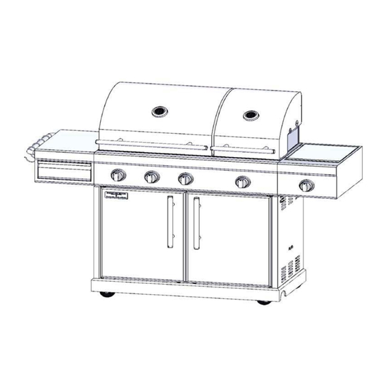
- Page 1 63 000 BTU double lid natural gas grill PC 1001 1024 NG 817258 160cm x 124.5cm x 55.24cm / 63” x 49” x 21.75” assembley instruction IMAGE OF PRODUCT LINE DRAWING...
- Page 2 SAVE THESE IN S T RU C TION S F O R FUTURE R EFE R E N CE . IF Y O U A R E ASSEMB L ING T H I S U NIT FOR S O ME ON E E L SE , GI V E T H I S MA N U A L TO HIM O R HER TO SAVE FOR FUTURE R EFE R E N CE .
- Page 3 Do not store or use gasoline or other flammable liquids or vapours in the vicinity within 7 .62 m/25 ft of this or any other appliance. WARNING: Improper installation, adjustment, alteration, service or maintenance can cause injury or property damage. Read the installation, operation and maintenance instructions thoroughly before installing or servicing this equipment.
- Page 4 GRILL OPERATION 1- 2 -3 Before grilling: 1. Keep your grill a safe distance away from your property.* 2. Always perform a leak-test on all connections and hoses.* 3. Keep children away from the grill. During grilling: To avoid tripping safety valves, please follow these instructions carefully! 1.
- Page 5 Please refer to the owner’s manual for details. WARNING Do not store or use gas oline or other flammable liquids or vapor in the vicinity of this or any other appliance An LP cylinder not connected for use shall not be stored in the vicinity of this or any other appliance. Do not fill the gas cylinder beyond maximum fill-line.
-
Page 6: Table Of Contents
SA FE T Y IN S TR U CTION S Alway s read and understand the W A RNIN GS and IN S TRUCTION S that are contained in this manual before attempting to use this gas barbecue grill, to prevent po ss ible bodily injury or property damage. -
Page 7: Sectio N O Ne
S E C T I O N O N E SA FE T Y IN S TR U CTION S NOTE: The use and in s tallation of this product mu s t conform to local codes. In the absence of local codes, use the National Fuel Gas Code, AN S I Z223.1/NFPA54. - Page 8 3. Always open the grill lid carefully and slowly as heat and steam trapped within the grill could cause severe burns. 4. Always place your grill on a hard and level surface far away from combustible materials and structures. An asphalt or blacktop surface may not be acceptable for this purpose.
- Page 9 14. Do not att em pt to move the grill while it is lit. 15. Do not use the grill unle ss it is COMPLETELY a ssem bled and all part s are s ecurely fa s tened and tightened. 16.
- Page 10 Clean and inspect the hose before each use. If there is evidence of abrasion, wear, cuts or leaks, the hose must be replaced prior to operation. The replacement hose assembly should be in accordance with the manufacturer’s specifications. 4. Move gas hoses as far away as possible from hot surfaces and dripping hot grease.
- Page 11 Always confirm that this grill is not positioned under the overhang of a house, a garage or other structure before lighting it. An overhang will serve to deflect flare-ups and radiated heat into the structure itself, which could result in a fire. 3.
- Page 12 or in the vicinity of any other heating-generating appliance, because of the danger of starting a fire. 9. Always confirm that the installation of this grill conforms with the requirements of all local codes or, in the absence of applicable local codes, with either the National Fuel Gas Code, ANSI Z223.NFPA 54 or CAN/CGA-B149.2.
-
Page 13: Gener Al Inform Ation
Inspect the grill before each use. 1. Inspect all hoses and connections and make certain they are secure. 2. Check and clean the burner venturi tubes for spiders and insect nests by removing the burner and inserting a bottle brush cleaner into each tube to make sure the passage is clear. -
Page 14: Sectio N T Wo
S E C T I O N T W O PARTS LIST/DESCRIPTION Body assembly Back panel Left side shelf Storage basket Cart Base 1pcs Right side shelf Right door Grease cup Right side panel 1pc Grease cup support Storage basket support Left warming rack 1pc Latch magnet G..Right warming rack 1pc... - Page 15 HARDWARE LIST AA. Bolt (M6x15), 24 pcs BB. Flat washer 6.2X9X1.2 20pcs CC. Spring washer 6.2x16x1.0 20 pcs DD.Screwdriver ,1pc EE. Spring washer 4.2X6.5X1.2 4pcs FF. Flat Washer 4.2X10.5X1.0 4pcs GG. M4 nut ,4pcs HH. M4X12 Bolt 6pcs...
-
Page 16: Asse Mbly Instr Uctions
ASSEM BLY I NSTRUC TI O NS Remove all contents from the carton packaging. Make sure all parts are present before attempting assembly. Once the grill is fully assembled, go back and check to make certain all the bolts are secure. - Page 17 Step 2 (Cart back panel assembly) Loosen the four pre-installed bolts on the cart back panel (N) and allow 1/4 bolt’s length to extend from the cart back panel (N). Align the holes on cart left side panel (K) with the holes on the cart back panel (N).
- Page 18 Step 4 (Front beam assembly) Align the holes on cart left side panel (K) with the holes on front beam (M). Insert one M6 x 15 bolt (AA), one spring washer (BB) and one flat washer (CC) into each pre-drilled hole, then tighten the bolt by hand.
- Page 19 Step 6 (Install doors ) Insert the pin on the bottom of left door (L) into the pre-drilled hole on the left side of cart base (P). Push down the pin on the top of left door and insert it into the pre-drilled hole on left front side of front beam (M) Repeat the procedure with the right door (Q) and front beam (M).
- Page 20 Step 8 (Side shelves assembly) Loosen the eight pre-installed bolts on both side shelves and allow 1/4 bolt’s length extend out of side shelves. Align the holes on the right side shelf (C) with the holes on the body assembly, and then tighten the bolts by hand.
- Page 21 tep 10 (Install the side burner and side burner frame) Align the holes on the side burner frame (W) with the holes on the right side shelf (C) Screw the M4X12 bolt (HH), flat washer (FF),Spring washer (EE) and M4 Nut (GG) into each pre-drilled holes by screwdriver provided Put the side burner grate (X) upon the side...
- Page 22 Step12 (Install the grease cup, grease cup support and natural gas hose) Hook the grease cup support (E) into the grooves beneath the grease pan. Put the grease cup (D) onto the grease cup support.(E) Keep the natural gas hose, quick release connector and gas supply connection securely, as shown in diagram.
-
Page 23: Sectio N Three
S E C T I O N T H R E E SAFE T Y CAUTION: Your natural gas grill has been designed to operate on natural gas only, at a pressure of seven inches water column (7" W.C /1.7Kpa). Check with your gas utility for local gas pressure, because in some areas natural gas pressure varies. -
Page 24: N At Ural Gas Connection
NATU R AL GAS CO N N EC TI O Co nne c t a m anu al shut - o f f valve to g as sup pl y line. Ap p ly se aling co mp o und o r pip e t hre ad t ap e o f t he t y p e resist ant to t he a c tio n o f n at ural gas o n all m ale pip e thre ads. - Page 25 WARNING: Burner valves are pre-tested at the factory to operate on natural gas. Do not attempt to convert or change DANGER: To prevent fire or explosion hazard when testing for a leak: 1. Always perform the leak- t est before lighting the grill and each time the natural gas hose is connected for use.
-
Page 26: Leak-Testing
LE AK-TESTI N G BEFO RE TESTI N G M ake sure t h at all p a ckaging m at erial is remove d fro m t he grill in clu ding t he burner tie - down st raps. D O N OT SMO KE WH ILE LE AK-TESTI N G N E VER LE AK-TEST WITH AN O PEN FL A ME. -
Page 27: Sectio N Four
S E C T I O N F O U R LI G HTI N G I NSTRUC TI O NS D A NGER: Failure to open lid while igniting the grill’ s burners or not waiting 5 minute s to allow gas to clear if the grill does not light, may re s ult in an explo s ion, which could cause serious injury or death. - Page 28 5. A f ter b urner ignite s, rep e at t he pro ce dure wit h any ot h er b urner d esire d. 6. Adjust val ve kno b (s) to desire d co o king te mp erat ure. Using t he lighting stick to light t he main burners 1.
- Page 29 SI D E BU RN ER Inst ruc tio ns 1. O p en lid w hile lighting the b urner. Lid must rem ain o p en w hile b urner is lit. 2. Val ve must b e in th e O FF p ositio n. 3.
- Page 30 Fig. C obser ve flame height w hen lit: Flame sh ould be a blue/yellow col our, bet we en 1 and 2 inches high (2.5-5 cm) I N FR ARED BU RN ER Lighting t he infrare d burner 1.
-
Page 31: Excess Flow Safet Y Valve Reset
WARNING: Always monitor the grill closely when cooking and turn the flame level down to LOW or OFF, if flare- ups intensify. SH UT TI N G O FF BU RN ERS 1. Alw a ys turn t he valve kno b (s) clo ckw ise to th e H IG H p osition, t hen press and turn t o O FF. -
Page 32: Sectio N Five
8. Wait for at le a s t 5 mi n ut e s . 9. Re co nn e c t t h e n at ural g as h o s e. 10. S l ow l y turn t h e n at ural g as valve ¼ turn at a tim e a n d h a ve t h e val ve all t h e wa y o p e n. - Page 33 DO NOT clean any grill part in a self-cleaning oven. The extreme heat will damage the finish. Burning of f t he grill af t er ever y use (ap prox. 15 minutes) will ke ep exce ssive fo o d residue fro m b uilding up Re co mme nd e d cle aning ma t erials M ild dishwashing liquid d et erg ent...
-
Page 34: Troublesh O Oting
Flam e tam ers Cle an residue wit h wire b rush and wash wit h so ap y wat er. Rinse wit h wat er Gre ase pan/Gre ase c ups Perio dicall y empt y t he gre ase p an/gre ase cups and cle an wit h a dishwashing det erg ent an d hot wat er so lutio n. - Page 35 PRO BLEM P OSSI BLE C AUSE SO LUTI O N Burne r will not ignite Wires and/or ele ctrode Clean wire and/or electrode covered with cooking with r ubbing alcohol. using knobs or ignit er. residue. Electrode and b urners Wip e dr y with cloth are wet.
- Page 36 SOL UT I ON PRO BLEM P OSSI BLE C AUSE Out of gas Sudde n drop in gas f low Call your local or re duce d f lame height. gas comp any Excess flow safet y device Refer to the ”Exce ss flow safet y valve reset”...
- Page 37 PRO BLE OSSI BLE C AUSE SO LUTI O N Adjust (lo w er) temp erat ure Excessive coo king accordingly temp erature Pe rsist ent gre ase fire. G re ase trapp ed by food Turn knobs to O FF. build -up around b urner system.
-
Page 38: Sectio N Six
S E C T I O N S I X LIMITED WARR A NT WARR A NT Y PRO GR A M: Pro o f o f p urch ase is re quire d to a cce s s this w arrant y pro gram, which is in ef fe ct fro m t he d at e o f p urch ase. - Page 39 S o me p rovin ce s d o not allow th e limit atio n or exclusio n o f in cid ent al o r co nse qu ential d am age s, so t he ab ove limit atio ns or exclusio ns m ay not app l y to you.
- Page 40 N O T E S A N D O B S E R VAT I O N S...
Need help?
Do you have a question about the 63 000 BTU and is the answer not in the manual?
Questions and answers