Table of Contents
Advertisement
Quick Links
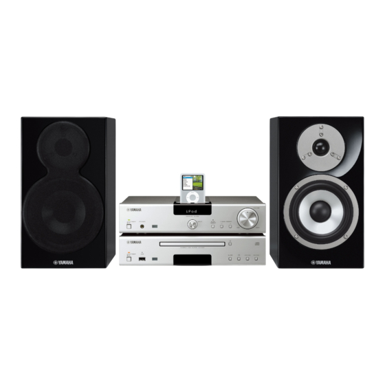
The MCS-1330 consists of the R-1330, CD-1330 and NS-BP400.
This service manual is for the CD-1330.
For service manual of the R-1330 and NS-BP400, please refer to the following publication number:
MCS-1330 は、R-1330、CD-1330 および NS-BP400 で構成されています。
このサービスマニュアルは CD-1330 用です。
R-1330、NS-BP400 用のサービスマニュアルは下記管理ナンバーを参照してください。
This manual has been provided for the use of authorized YAMAHA Retailers and their service personnel.
It has been assumed that basic service procedures inherent to the industry, and more specifi cally YAMAHA Products, are already known
and understood by the users, and have therefore not been restated.
WARNING:
IMPORTANT:
The data provided is believed to be accurate and applicable to the unit(s) indicated on the cover. The research, engineering, and service
departments of YAMAHA are continually striving to improve YAMAHA products. Modifications are, therefore, inevitable and
specifi cations are subject to change without notice or obligation to retrofi t. Should any discrepancy appear to exist, please contact the
distributor's Service Division.
WARNING:
IMPORTANT:
■ CONTENTS
TO SERVICE PERSONNEL ........................................2-4
SYSTEM COMPOSITION / システム構成 .......................6
FRONT PANEL ...............................................................6
REAR PANELS ...........................................................7-8
SPECIFICATIONS / 参考仕様 .........................................9
INTERNAL VIEW .......................................................... 10
DISASSEMBLY PROCEDURES / 分解手順 ........... 11-13
TEST MODE / テストモード ................................... 14-15
UPDATING FIRMWARE /
ファームウェアの書き込み ..................................... 16-20
1 0 1 1 3 0
MICRO COMPONENT SYSTEM
CD-1330
R-1330/NS-BP400: 101127
R-1330/NS-BP400: 101127
IMPORTANT NOTICE
Failure to follow appropriate service and safety procedures when servicing this product may result in personal injury,
destruction of expensive components, and failure of the product to perform as specifi ed. For these reasons, we advise
all YAMAHA product owners that any service required should be performed by an authorized YAMAHA Retailer or
the appointed service representative.
The presentation or sale of this manual to any individual or fi rm does not constitute authorization, certifi cation or
recognition of any applicable technical capabilities, or establish a principle-agent relationship of any form.
Static discharges can destroy expensive components. Discharge any static electricity your body may have
accumulated by grounding yourself to the ground buss in the unit (heavy gauge black wires connect to this buss).
Turn the unit OFF during disassembly and part replacement. Recheck all work before you apply power to the unit.
Copyright © 2008
This manual is copyrighted by YAMAHA and may not be copied or
redistributed either in print or electronically without permission.
MCS-1330
CD PLAYER
SERVICE MANUAL
DISPLAY DATA .............................................................21
IC DATA ...................................................................22-27
PIN CONNECTION DIAGRAMS .............................28-29
BLOCK DIAGRAM ........................................................31
PRINTED CIRCUIT BOARDS .................................32-38
SCHEMATIC DIAGRAMS .......................................39-41
REPLACEMENT PARTS LIST ................................43-53
REMOTE CONTROL .....................................................54
All rights reserved.
P.O.Box 1, Hamamatsu, Japan
animate '08.11
Advertisement
Table of Contents

Related Manuals for Yamaha CD-1330


Summary of Contents for Yamaha CD-1330
-
Page 1: Table Of Contents
This manual has been provided for the use of authorized YAMAHA Retailers and their service personnel. It has been assumed that basic service procedures inherent to the industry, and more specifi cally YAMAHA Products, are already known and understood by the users, and have therefore not been restated. -
Page 2: To Service Personnel
CD-1330 ■ TO SERVICE PERSONNEL AC LEAKAGE 1. Critical Components Information WALL EQUIPMENT TESTER OR Components having special characteristics are marked OUTLET UNDER TEST EQUIVALENT must be replaced with parts having specifications equal to those originally installed. 2. Leakage Current Measurement (For 120V Models Only) - Page 3 CD-1330 WARNING: Laser Safety 警告:レーザーの安全対策 This product contains a laser beam component. This 本機はレーザー光線を放射する部品を搭載しています。 component may emit invisible, as well as visible radi- この部品が放射するレーザー光線は目に損傷を起こしま ation, which may cause eye damage. To protect your す。このレーザー光線から目及び肌を保護するために、 eyes and skin from laser radiation, the following pre- 本機の修理作業中は下記の注意を厳守してください。...
- Page 4 CD-1330 T model U, K, A, G models L model Warning for power supply The primary side of the power supply carries live mains voltage when the player is connected to the mains even when the player is switched off ! This primary area is not shielded so it is possible to accidentally touch copper tracks and/or components when servicing the player.
-
Page 5: Prevention Of Electrostatic Discharge
CD-1330 ■ PREVENTION OF ELECTROSTATIC DISCHARGE Some semiconductor (solid state) devices can be damaged easily by static electricity. Such components commonly are called Electrostatically Sensitive (ES) Devices. Examples of typical ES devices are integrated circuits and some field-effect transistors and semiconductor “chip” components. The following techniques should be used to help reduce the incidence of component damage caused by electro static discharge (ESD). -
Page 6: System Composition / システム構成
■ SYSTEM COMPOSITION / システム構成 The MCS-1330 consists of the R-1330, CD-1330 and MCS-1330 は、R-1330、CD-1330 および NS-BP400 で NS-BP400. 構成されています。 MCS-1330 ▼ NS-BP400 ▼ NS-BP400 ▼ R-1330 ▼ CD-1330 ■ FRONT PANEL CD-1330 (U, T, K, A, G, L, J models) -
Page 7: Rear Panels
CD-1330 ■ REAR PANELS CD-1330 (U model) Bottom view CD-1330 (T model) CD-1330 (K model) - Page 8 CD-1330 CD-1330 (A model) CD-1330 (G model) CD-1330 (L model) Bottom view CD-1330 (J model)
-
Page 9: Specifications / 参考仕様
CD-1330 ■ SPECIFICATIONS / 参考仕様 ■ Player Section / プレーヤー部 Dimensions (W x H x D) / 寸法(幅 × 高さ × 奥行き) Playback System / 再生システム ....300 x 67 x 300 mm (11-3/4" x 2-5/8" x 11-3/4") ................. CD, CD-R/RW Weight / 質量... -
Page 10: Internal View
CD-1330 ■ INTERNAL VIEW Top view OPERATION (5) P.C.B. OPERATION (7) P.C.B. (L model) DIGITAL (2) P.C.B. DIGITAL (1) P.C.B. OPERATION (3) P.C.B. OPERATION (4) P.C.B. Loader Mechanism Ass’y OPERATION (9) P.C.B. OPERATION (1) P.C.B OPERATION (6) P.C.B OPERATION (8) P.C.B. -
Page 11: Disassembly Procedures / 分解手順
CD-1330 ■ DISASSEMBLY PROCEDURES / 分解手順 (Remove parts in the order as numbered.) (番号順に部品を取り外してください。 ) Disconnect the power cable from the AC outlet. AC 電源コンセントから、電源コードを抜いてください。 1. Removal of Top Cover 1. トップカバーの外し方 ➀ ➁ a. ①のネジ 4 本、②のネジ 2 本を外します。 (Fig. 1)... - Page 12 CD-1330 3. Removal of OPERATION (3) P.C.B. 2. OPERATION (3) P.C.B. の外し方 ➅ ➆ a. Remove 4 screws ( ) and 2 screws ( ). (Fig. 2) a. ⑥のネジ 4 本、⑦のネジ 2 本を外します。 (Fig. 2) b. Remove CB1. (Fig. 2) b.
- Page 13 CD-1330 When checking the P.C.B.s: P.C.B. をチェックする場合には: • Spread the rubber sheet and the cloth. Then place ・ ゴムシートと布を敷き、 その上にサブシャーシユニッ the sub chassis unit on the cloth and check it. (Fig. 3) トを置いてチェックします。 (Fig. 3) • Reconnect all cables (connectors) that have been ・...
-
Page 14: Test Mode / テストモード
CD-1330 ■ TEST MODE / テストモード Check the FL display and indicators for display/indication FL ディスプレイとインジケーターの表示状態をチェック condition. します。 ● Check the FL display and Indicators ● FL ディスプレイとインジケーターの確認 1. While pressing those 3 keys of this unit as indicated 1. 本機の下図に示す 3 つのキーを押しながら ON/ in the figure below, press the “ON/STANDBY, OFF”... - Page 15 CD-1330 ● Operation Procedure of Test Mode ● テストモード時の操作 Function list of panel keys / テストモード時のパネルキー Panel key / パネルキー Function / 機能 Display / 表示 OPEN/CLOSE Disc tray open/close / ディスクトレイ オープン/クローズ OPEN / CLOSE PLAY/PAUSE – – STOP Trace off / トレース...
-
Page 16: ファームウェアの書き込み
CD-1330 ■ UPDATING FIRMWARE / ファームウェアの書き込み After replacing the following parts update the latest firm- 下記の部品を交換した場合、下記の手順により最新の ware according to the following procedure. ファームウェアの書き込みを行ってください。 DIGITAL P.C.B. DIGITAL P.C.B. Microprocessor (IC304) of DIGITAL P.C.B. DIGITAL P.C.B. のマイコン(IC304) ● Required tools ● 必要なツール... - Page 17 CD-1330 ● Confirmation of firmware version ● ファームウェアバージョンの確認 Before and after updating the firmware, check the firm- ファームウェア更新の前後に、ファームウェアのバー ware version. ジョンを確認します。 1. While pressing the “PLAY/PAUSE” and “STOP” 1. 本機の PLAY/PAUSE キーと STOP キーを押し keys, press the “ON/STANDBY, OFF” switch of this ながら、...
- Page 18 CD-1330 ● Connection ● 接続 Connect the writing port of this unit to the serial 本 機 の 書 き 込 み 用 ポ ー ト と PC の シ リ ア ル ポ ー ト port (RS232C) of the PC with RS232C cross cable, (RS232C)を下記のように接続します。...
- Page 19 CD-1330 3. Start up FlashSta.exe, the screen will appear as 3. FlashSta.exe を立ち上げます。 shown below. (Fig. 5) すると下記の画面が表示されます。 (Fig. 5) Select Internal flash memory Internal fl ash memory を選択します Select the port of RS-232C 接続している RS-232C ポートを選択します Fig. 5 4. Select the port and data to be transmitted. (Fig. 5) 4.
- Page 20 CD-1330 6. Click [E.P.R.], the screen appears as shown below. 6. [E.P.R]をクリックすると、下記の画面が表示さ (Fig. 7) れます。 (Fig. 7) Click [OK] to start writing. (Fig. 7) [OK]をクリックし、書き込みを開始します。 (Fig. 7) Writing being executed. 書き込み中 Fig. 7 7. When the program transmission is completed, the 7.
-
Page 21: Display Data
CD-1330 ■ DISPLAY DATA ● V101 : 13-ST-81GINK (OPERATION (1) P.C.B.) ● PIN CONNECTION Pin No. Connection Q13G Pin No. Connection RESET Pin No. Connection LGND PGND Note: 1) F1, F2 ..Filament 2) NP ..No pin 3) NX ..No extended pin 4) DL .. -
Page 22: Ic Data
CD-1330 ■ IC DATA IC304: M30302FAPFP (DIGITAL P.C.B.) Single-chip 16-bit microprocessor Port P0 Port P1 Port P2 Port P3 Port P4 Port P5 Port P6 Peripheral function System clock generator A/D converter Timer (16-bit) (10-bit 18-channel COUT Input (timer A) x3... - Page 23 CD-1330 Port Name Function Name Detail of Function P9_6/ANEX1 (No connected) CLAMP_SW2 P9_5/ANEX0 Clamp SW2 CLAMP_SW1 P9_4 Clamp SW1 TRAY_SW4 P9_3 TRAY_SW3 P9_2/TB2IN Tray SW3 / Loader mechanism specification confirm TRAY_SW2 P9_1/TB1IN Tray SW2 TRAY_SW1 P9_0/TB0IN Tray SW1 BYTE BYTE...
- Page 24 CD-1330 Port Name Function Name Detail of Function 61 FL_RES P3_1/A9 FL control 62 VCC2 VCC2 63 FL_CS P3_0/A8 FL control 64 VSS 65 USB_FLG P2_7/A7 (No connected) 66 USB_EN P2_6/A6 (No connected) 67 SYS_RICO_C P2_5/A5 (No connected) 68 SYS_RICO_U...
- Page 25 CD-1330 IC604: MN103SFB5KYAA (DIGITAL P.C.B.) USB microprocessor INTERFACE 32 bit MEMORY 256 KByte 8 KB FLASH MICRO- DMA 4 CH MEMORY PROCESSOR CORE DATA 8 KByte I/O port INTERRUPT TIMER 34 pcs (3 V type) 8 pcs (5 V type)
- Page 26 CD-1330 Port Name Function Name Detail of Function N.C. USBNOC USB over-current input (negative polarity) USBNPP USB, VBUS power output control terminal (negative polarity) USBD- USB D- terminal AVSS Ground / Analog power supply for USB / Connect to VSS.
- Page 27 CD-1330 Port Name Function Name Detail of Function N.C. 53 VSS Ground 54 STREQ PD5/IRQ2 External interrupt request signal input terminal 55 CS PD4/IRQ1 External interrupt request signal input terminal 56 N.C. 57 TX PD1/SBI2 Clock synchronization/start stop synchronization serial terminal...
-
Page 28: Pin Connection Diagrams
CD-1330 ■ PIN CONNECTION DIAGRAMS • ICs AN41010A-VF BD5229G-TR BD9870FPS-E2 DSD1791DBR M12L16161A-7TG M30302FAPFP MN103SFB5KYAA MN6627971YB OP275GSR PQ033ES3MXP R1154N033B-TR-F R1172S331B-E2-F R5523N001A-TR-F RP131S501D-E2-F TC74VHCT08AFT TC7SH08F • Diodes D4SBN20-7101 RS203M-B-C-J80 1N4002S 1SS355 FM203-W TE MA-8039-H MA8047-H MA8056-M 5.6V Anode MA8062-M Anode MA8130-M MA8300-M 30.0V RB050LA-40TR TP –... - Page 29 CD-1330 • Transistors 2SA1037K 2SB1257 2SB709A 2SC4488 2SK208 5HP02C-TB-E 2SC2412K 2SD2014 RSR025N03 2SD1938F DTC114EKA MCH6612-TL-E RSR025P03TL DTC144EKA DTA144EKA 1: Source 1 2: Gate 1 3: Drain 2 1: GND 4: Source 2 2: IN 5: Gate 2 3: OUT 6: Drain 1...
- Page 30 CD-1330 MEMO...
-
Page 31: Block Diagram
CD-1330 ■ BLOCK DIAGRAM OPERATION D104 POWER Indicator SW101, SW102, U101 → CB161 V101 D102 PURE DIRECT Indicator SW105-107 Remote SCHEMATIC DIAGRAM USB Connector FL-Display D103 USB Indicator Front Panel Keys Front Panel → DIGITAL USB+5 IC606 FL_CLK/FL_Data SCHEMATIC DIAGRAM... -
Page 32: Printed Circuit Boards
CD-1330 POINT D 1 / Pin2, 2 / Pin1 of IC307 ■ PRINTED CIRCUIT BOARDS POINT A XL601 (Pin 109 of IC602) • Semiconductor Location DIGITAL (1) P.C.B. (Side A) 2 pin Ref no. Location Ref no. Location Ref no. Location Ref no. - Page 33 CD-1330 • Semiconductor Location DIGITAL (1) P.C.B. (Side B) Ref no. Location Ref no. Location Ref no. Location D304 D313 D902 D306 D314 D903 D307 D317 IC803 D308 D603 Q300 D312 D802 Q601 IC803 DIGITAL (2) P.C.B. (Side B)
- Page 34 CD-1330 • Semiconductor Location OPERATION (1) P.C.B. (Side A) Ref no. Location Ref no. Location D101 Q104 D102 Q105 D104 Q106 OPERATION (9) IC802 Q107 (CB152) Q101 Q102 Q103 indicator CB101 POWER indicator OPERATION (1) P.C.B. (Side B)
- Page 35 CD-1330 OPERATION (3) P.C.B. (Side A) AGND OPERATION (4) (CB206) DIGITAL (1) (CB301) • Semiconductor Location OPERATION (3) P.C.B. (Side B) Ref no. Location Ref no. Location...
- Page 36 CD-1330 • Semiconductor Location OPERATION (4) P.C.B. (Side A) Ref no. Location D204 D205 D211 L model D212 D213 D214 W202B D215 DGND Q201 W204B T, K, J models MGND ACFL2 W203B ACFL1 FLGND DIGITAL (1) U, A, G models...
- Page 37 CD-1330 • Semiconductor Location OPERATION (4) P.C.B. (Side B) Ref no. Location D201 D206 OPERATION (5) P.C.B. (Side B) OPERATION (6) P.C.B. (Side B) OPERATION (7) P.C.B. (Side B)
- Page 38 CD-1330 OPERATION (8) P.C.B. OPERATION (8) P.C.B. (Side A) (Side B) DIGITAL (1) (CB609) CB161 OPERATION (9) P.C.B. OPERATION (9) P.C.B. (Side A) (Side B) OPERATION (1) (CB101) CB152 CB151 DIGITAL (1) (CB303)
-
Page 39: Schematic Diagrams
CD-1330 SCHEMATIC DIAGRAMS DIGITAL 1/3 DIGITAL (1) IC605 SDRAM CD CONTROLLER (Writing port) CB604 CD IN ACTUATOR DRIVER CURRENT LIMITER IC606 MICROPROCESSOR USB IN CB609 To Loader mechanism ass ’ y CB602 Page 42 to OPERATION (8)_CB162 CB603 (Writing port) To Loader mechanism ass ’... - Page 40 CD-1330 DIGITAL 2/3 DC/DC CONVERTER DIGITAL (1) Page 41 LEGULATOR to DIGITAL (2)_CB901 20.0 IC300 IC303 CB801 LEVEL SHIFTER IC802 IC308 IC803 IC308 CB303 DC/DC CONVERTER IC308 20.0 IC302 IC308 Page 43 to OPERATION (9)_CB151 MICROPROCESSOR IC304 IC311 CB300 LEGULATOR...
- Page 41 CD-1330 DIGITAL 3/3 DIGITAL (2) CB901 SYSTEM CONNECTOR IC901 JK901 IC901 Page 40 to DIGITAL (1)_CB801 IC901 IC901 IC901: TC74VHCT08AFT Quad 2-input AND gate ★ All voltages are measured with a 10MΩ/V DC electronic voltmeter. ● 電圧は、内部抵抗 10MΩの電圧計で測定したものです。 ★ Components having special characteristics are marked and must be replaced ●...
- Page 42 CD-1330 OPERATION 1/2 OPERATION (1) 30.3 30.3 30.3 OPERATION (8) CB161 CB162 CB101 Page 39 to DIGITAL (1)_CB609 POWER indicator OPERATION (3) IC802 -11.6 -11.6 -11.6 -11.6 D/A CONVERTER 11.5 -11.6 -11.6 OUTPUT IC1: DSD1791DBR Page 40 24-bit, 192 kHz sampling, advanced segment, audio stereo digital-to-analog converter -11.6...
- Page 43 CD-1330 OPERATION 2/2 OPERATION (4) CB206 Page 42 to OPERATION (3)_CB1 OPERATION (7) L model 10.0 20.0 VOLTAGE SELECTOR 10.0 29.6 39.1 39.1 30.3 31.0 OPERATION (6) 29.6 20.0 31.0 ON/STANDBY OFF POWER TRANSFORMER 10.0 20.0 27.4 Page 40 OPERATION (5) to DIGITAL (1)_CB300 10.0...
-
Page 44: Replacement Parts List
CD-1330 ■ REPLACEMENT PARTS LIST • ELECTRICAL COMPONENT PARTS WARNING ● Components having special characteristics are marked and must be replaced with parts having specifications equal to those originally installed. ● 印のある部分は、安全確保部品を示しています。部品の交換が必要な場合、パーツリストに記載されている部品を使用し てください。 ● 部品価格ランクは、予告なく変更することがあります。 ABBREVIATIONS IN THIS LIST ARE AS FOLLOWS: C.A.EL.CHP... - Page 45 CD-1330 P.C.B. DIGITAL Ref No. Part No. Description Remarks Markets 部 品 名 ランク WQ596900 P.C.B. DIGITAL PCB DIGITAL CB300 VB390400 CN.BS.PIN ベースピン CB301 VE352600 CN.BS.PIN コネクタベースポスト CB303 VQ045600 CN.BS.PIN 27P SE FFCコネクター CB304 VP682300 CN.BS.PIN FFCコネクター CB601 WQ289300 CN 24P TE FFC / FPCコネクタ...
- Page 46 CD-1330 P.C.B. DIGITAL Ref No. Part No. Description Remarks Markets 部 品 名 ランク C620 US135100 C.CE.CHP 0.1uF チップセラコン C621 US062680 C.CE.CHP 680pF 50V B チップセラコン C622 US044220 C.CE.CHP 0.022uF 25V B チップセラコン C623 US135100 C.CE.CHP 0.1uF チップセラコン C624 US063100 C.CE.CHP 1000pF 50V B チップセラコン...
- Page 47 CD-1330 P.C.B. DIGITAL Ref No. Part No. Description Remarks Markets 部 品 名 ランク C803 US064100 C.CE.CHP 0.01uF 50V B チップセラコン C806-807 US064100 C.CE.CHP 0.01uF 50V B チップセラコン C808-810 US135100 C.CE.CHP 0.1uF チップセラコン C817 US063220 C.CE.CHP 2200pF 50V B チップセラコン C901-909 US064100 C.CE.CHP 0.01uF...
- Page 48 CD-1330 P.C.B. OPERATION Ref No. Part No. Description Remarks Markets 部 品 名 ランク WQ597000 P.C.B. OPERATION PCB OPERATION WQ597100 P.C.B. OPERATION PCB OPERATION WQ597200 P.C.B. OPERATION PCB OPERATION WQ597300 P.C.B. OPERATION PCB OPERATION WQ597400 P.C.B. OPERATION PCB OPERATION LB918030 CN.BS.PIN ベース付ポスト CB101 VQ045100 CN.BS.PIN FFCコネクター CB151 VQ047800 CN.BS.PIN...
- Page 49 CD-1330 P.C.B. OPERATION Ref No. Part No. Description Remarks Markets 部 品 名 ランク C123 US064100 C.CE.CHP 0.01uF 50V B チップセラコン C151 WG782400 C.EL 22uF ケミコン C152-153 WG780700 C.EL 47uF ケミコン C162 US064100 C.CE.CHP 0.01uF 50V B チップセラコン C201-203 V6185300 C.CE.SAFTY 0.01uF 275V 規格認定コンデンサ...
- Page 50 CD-1330 P.C.B. OPERATION Carbon Resistors Value 1/4W Type Part No. 1/6W Type Part No. Value 1/4W Type Part No. 1/6W Type Part No. Ref No. Part No. Description Remarks Markets 部 品 名 ランク 1.0 Ω HJ35 3100 HF85 3100 11 kΩ...
- Page 51 CD-1330 • OVERALL ASS'Y L model 5 (1) 6 (4) 1-43 6 (6) 1-41 6 (5) L model 1-19 6 (8) 1-18 1-40 1-15 6 (7) L model 5 (2) 1-18 1-42 1-40 6 (9) 1-20 1-50 1-22 1-17 1-41...
- Page 52 CD-1330 Ref No. Part No. Description Remarks Markets 部 品 名 ランク Ref No. Part No. Description Remarks Markets 部 品 名 ランク 1-11 WQ133500 FRONT PANEL フロントパネル WQ606800 DAMPER 25x45x2 ダンパー 1-11 WQ133100 FRONT PANEL フロントパネル WR154600 DAMPER CARD 40x55 ダンパー カード 1-14 WQ147300 WINDOW ウィンドウ...
-
Page 53: Remote Control
CD-1330 ■ REMOTE CONTROL ● Receiving Code / 受信コード CD-1330 The remote control of the MCS-1330. Mode select CD/USB mode Function Code REPEAT STOP RANDOM REVERSE FORWARD PLAY/PAUSE DISPLAY...
Need help?
Do you have a question about the CD-1330 and is the answer not in the manual?
Questions and answers