Table of Contents
Advertisement
Quick Links
Advertisement
Table of Contents

Related Manuals for LevelOne FCS-1152


Summary of Contents for LevelOne FCS-1152
- Page 1 Fixed Network Camera Hardware User Manual FCS-1152, FCS-1153 Ver. 2014/06/04...
-
Page 2: Table Of Contents
Hardware Manual Table of Contents Precautions ............... 4 Safety Instructions ....................6 Introduction ..............7 The List of Models ....................7 Package Contents ..................... 7 Physical Description ....................8 Before Installation ............10 How to Connect DI/DO and Audio Devices (Optional) ........10 How to Connect DI/DO Devices ............ - Page 3 Hardware Manual FCS-1152 ............... 錯誤! 尚未定義書籤。 How to Install / Remove the Memory Card............25 How to Insert the Memory Card ............25 How to Remove the Memory Card ............25 How to Replace the Lens ..................26 Accessing the Camera............ 28 Configure the IP Addresses ...................
-
Page 4: Precautions
Hardware Manual Precautions Read these instructions You should read all the safety and operating instructions before using this product. Heed all warnings You must adhere to all the warnings on the product and in the instruction manual. Failure to follow the safety instruction given may directly endanger people, cause damage to the system or to other equipment. - Page 5 Hardware Manual Federal Communications Commission Statement This equipment has been tested and found to comply with the limits for a class B digital device, pursuant to Part 15 of the FCC Rules. These limits are designed to provide reasonable protection against harmful interference in a residential installation.
-
Page 6: Safety Instructions
Hardware Manual Safety Instructions Cleaning Disconnect this video product from the power supply before cleaning. Attachments Do not use attachments not recommended by the video product manufacturer as they may cause hazards. Do not use accessories not recommended by the manufacturer Only install this device in a dry place protected from weather Servicing Do not attempt to service this video product yourself. -
Page 7: Introduction
From the installation perspective, these models are very similar; therefore one manual is used for all of them. Package Contents Camera Lens (FCS-1153) Lens (FCS-1152) Fixed focal lens with Vari-focal lens with manual manual focus and fixed iris focus and DC iris... -
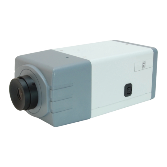
Page 8: Physical Description
Hardware Manual Physical Description FCS-1152 FCS-1153 1) Ethernet Port Connects to a network using an Ethernet cable. 2) Memory Card Slot Insert a memory card into this slot for local recording purposes. See How to Install / Remove the Memory Card on page 25 for more information. - Page 9 Hardware Manual How to do the reset? Using a pointed object, such as a paper clip, press and hold the reset button for at least 5 seconds or until the Power LED goes off. 4) Power LED The Power LED turns on when the camera is powered on and the system is running. 5) Digital Input / Output (DI/DO) and Audio Input / Output This connector connects to digital input or output devices, such as an alarm trigger, panic button, etc., as well as audio input and output devices, such as microphones and speakers.
-
Page 10: Before Installation
Hardware Manual Before Installation This section describes the procedures in preparing the Digital Input and Output (DI/DO) and Audio Input and Output devices that you can connect to the camera using the bundled terminal blocks. The use of these devices, however, is optional. How to Connect DI/DO and Audio Devices (Optional) Depending on your surveillance needs, you may connect digital input / output or audio input / output devices to your camera. - Page 11 Hardware Manual Press and hold the orange tab as you insert the wire through the pin slot, then release the orange tab to secure the wire. For DI/DO Use For Audio Use To connect digital input / output devices (DI/DO), map the pins to one of the pin combinations below: Device Mapping Instructions...
- Page 12 Hardware Manual Typical Connection Based on these specifications, if the DI device has a voltage of 0V ~ 30V or the DO device has a voltage of < 24V (< 50mA), then the camera can supply internal power to these devices and there is no need to connect the DI/DO device to an external power source.
- Page 13 Hardware Manual The illustration below is a graphic example of connecting a relay to a high voltage DO device. 110V-220V AC External Power Source Relay (DO1 Device) Camera Illuminator NOTE: For more information on DI/DO connections, please refer to the Knowledge Base article on our website.
-
Page 14: How To Connect Audio Devices
Hardware Manual How to Connect Audio Devices Audio input / output devices, such as an active microphone or speaker can be connected to the camera using the supplied terminal block. Press and hold the orange tab as you insert the wire through the pin slot, then release the orange tab to secure the wire. -
Page 15: Indoor Installation Procedures
1. Unpack the camera and check the bundled camera lens. The camera comes with one of the following lens. FCS-1153 FCS-1152 2. Pull to remove the cap covering the camera lens holder. - Page 16 Hardware Manual 3. Twist and pull to remove the cap covering the threaded end of the lens. FCS-1153 FCS-1152 Attach the lens to the camera. 4. For cameras models FCS-1152, connect the lens cable to the DC-iris port.
-
Page 17: Step 2: Attach The Mounting Block
Hardware Manual Step 2: Attach the Mounting Block Determine where you want to install the camera: on the ceiling or on the wall. If the camera will be installed on the ceiling, attach the mounting block on the top side of the camera. -
Page 18: Step 3: Mount The Indoor Bracket
Hardware Manual Step 3: Mount the Indoor Bracket NOTE: Before installing the bracket, make sure the ceiling or wall can bear more than the weight of the camera and its accessories. Install the indoor bracket to the ceiling or wall using the three (3) screws included in the bracket package. - Page 19 Hardware Manual 2. Slightly loosen the knurled knob. 3. Screw the camera to the bracket by its mounting block. 4. Tighten the hand knob until the camera is secured to the bracket. 5. Adjust the camera angle.
- Page 20 Hardware Manual 6. Tighten the knurled knob to fix the camera position. 7. Remove the protective cap from the lens (if any).
-
Page 21: Step 5: Connect The Cable(S)
Hardware Manual Step 5: Connect the Cable(s) 1. Connect the network cable to the Ethernet port of the camera. 2. If necessary, connect audio input/output or DI/DO devices to the camera. See How to Connect DI/DO and Audio Devices (Optional) on page 10 for more information. -
Page 22: Step 6: Access The Camera Live View
Step 7: Adjust the Viewing Angle and Focus Based on the live view, adjust the focus and the viewing angle of the camera. Adjustments vary depending on model, for detailed information, see: FCS-1153 on page 23 FCS-1152 on page 23... -
Page 23: Other Adjustments And Accessories
FCS-1153 Turn the lens knob left or right to adjust the focus. FCS-1152 The camera comes with the focus and viewing angle already fixed. If necessary, do the following to modify the focus and viewing angle. 1. Loosen the zoom lever screw, then turn left or right to adjust the viewing angle. - Page 24 Hardware Manual Focus Lever Screw 3. When done, tighten the lever screws to fix their position.
-
Page 25: How To Install / Remove The Memory Card
Hardware Manual How to Install / Remove the Memory Card The camera supports local video recording or saving of snapshots to a memory card. NOTE: Supports microSDHC and microSDXC cards. How to Insert the Memory Card Insert a memory card into the card slot with the metallic contacts facing down the camera. Push the card until it clicks into place. -
Page 26: How To Replace The Lens
Hardware Manual How to Replace the Lens Depending on your surveillance needs, the bundled lens can be replaced with a vari-focal lens with wider viewing angle or change to a DC-iris, etc. Contact your sales agent to purchase. To replace the bundled lens, do the following: 1. - Page 27 Hardware Manual 4. For lens with DC-iris, connect the lens cable to the DC-iris port of the camera. 5. Pull to remove the protective cap from the replacement lens.
-
Page 28: Accessing The Camera
Hardware Manual Accessing the Camera Configure the IP Addresses In order to be able to communicate with the camera from your PC, both the camera and the PC have to be within the same network segment. In most cases, it means that they both should have very similar IP addresses, where only the last number of the IP address is different from each other. - Page 29 Hardware Manual Double-click the mouse button on the camera model, the default browser of the PC is automatically launched and the IP address of the target camera is already filled in the address bar of the browser. If you work with our cameras regularly, then there is even a better way to discover the cameras in the network –...
- Page 30 Hardware Manual Use the default IP address of a camera: If there is no DHCP server in the given network, the user may have to assign the IP addresses to both PC and camera manually to make sure they are in the same network segment. When the camera is plugged into network and it does not detect any DHCP services, it will automatically assign itself a default IP: 192.168.0.100...
- Page 31 Hardware Manual Manually adjust the IP addresses of multiple cameras: If there are more than 1 camera to be used in the same local area network and there is no DHCP server to assign unique IP addresses to each of them, all of the cameras would then have the initial IP address of 192.168.0.100, which is not a proper situation for network devices –...
-
Page 32: Access The Camera
Hardware Manual Access the Camera Now that the camera and the PC are both having their unique IP addresses and are under the same network segment, it is possible to use the Web browser of the PC to access the camera. You can use any of the browsers to access the camera, however, the full functionality is provided only for Microsoft Internet Explorer. - Page 33 Hardware Manual prompted so. No other third party utilities are required to be installed in such case. The following examples in this manual are based on Internet Explorer browser in order to cover all functions of the camera. Assuming that the camera’s IP address is 192.168.0.100, you can access it by opening the Web browser and typing the following address into Web browser’s address bar: http://192.168.0.100 Upon successful connection to the camera, the user interface called Web Configurator would...
- Page 34 Hardware Manual To check the firmware version through the Web Configurator, access the Setup page and click System > System Info. For further operations, please refer to the Firmware User Manual.
Need help?
Do you have a question about the FCS-1152 and is the answer not in the manual?
Questions and answers