Table of Contents
Advertisement
Quick Links
Advertisement
Table of Contents

Related Manuals for LevelOne FCS-1122


Summary of Contents for LevelOne FCS-1122
-
Page 1: User Manual
LevelOne User Manual FCS-1122 Megapixel PoE Network Camera Ver 1.0... -
Page 2: Table Of Contents
Table of Contents Before You Use This Product ..............5 Package Contents ................... 5 Product Overview ................... 6 Device Appearance Description ..............7 LED Behavior ......................... 8 Extension I/O Terminal Block ..................9 Hardware Reset ......................10 System Requirements ....................11 Camera Connection ...................... - Page 3 IP Filter ..................48 Firmware Upgrade ..............48 Configuration ................48 Reset to default ................49 Reboot ..................49...
-
Page 4: General Public License
If you would like a copy of the GPL or other open source code in this software on a physical CD medium, LevelOne (Digital Data Communications) offers to mail this CD to you upon request, for a price of US$9.99 plus the cost of shipping. -
Page 5: Before You Use This Product
Before You Use This Product In many countries, there are laws prohibiting or restricting the use of surveillance devices. This Network Camera is a high-performance, web-ready camera which can be part of a flexible surveillance system. It is the user’s responsibility to ensure that the operation of this camera is legal before installing this unit for its intended use. -
Page 6: Product Overview
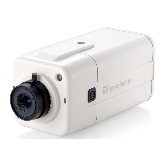
Product Overview The LevelOne FCS-1122 IP camera offers reliable and excellent video quality solution for 24-hour surveillance application. The camera offers highly efficient H.264 video compression, which reduces bandwidth and storage requirements without compromising image quality. M-JPEG and MPEG-4 are also supported for flexibility. Users can view live, motion image from anywhere by web browser or mobile phone via Internet or 3G network respectively. -
Page 7: Device Appearance Description
Device Appearance Description Light Sensor Status LED Built-in Microphone Power Connector Ethernet RJ45 10/100 Socket (DC12V In) Reset Button Extension I/O Terminal Block Microphone/Line In Audio Out Auto Iris Connector... -
Page 8: Led Behavior
LED Behavior Function LED Behavior Description Remark Hardware Front Left Status failure (Green) 1. Restoring settings Front Left Status Steady On 2. Normal (Green) Operation The LED can be 1. Power Off configured 2. Power On to be Status Unlighted till System unlighted setup... -
Page 9: Extension I/O Terminal Block
Extension I/O Terminal Block The Network Camera provides an extension I/O terminal block which is used to connect external input/output devices. The pin definitions are listed as below. Function Power +4.5V Digital Output Digital Input Ground RS-485 - RS-485 + DI/DO Diagram... -
Page 10: Hardware Reset
Hardware Reset Reset Button The Reset Button can be used to reboot the camera or restore it to factory default settings. If the camera experiences a problem, rebooting the camera may correct the problem. If the problem remains, please restore the camera to factory default settings and reinstall the software. -
Page 11: System Requirements
Installation System Requirements Operating System: Microsoft Windows XP Home Edition SP2 Microsoft Windows XP Professional SP2 Computer: IBM PC/AT Compatible CPU: Pentium 3GHz or faster Memory: 1024 MB or more Monitor: 1024 x 768 pixels or more, 24-bit True color or better Network Interface: 10/100Mbps Network interface card must be installed Web Browser:... -
Page 12: Camera Connection
Camera Connection Basic Connection (Without PoE) 1.1 If you have external devices such as sensors and alarms, please make connections with extension I/O terminal block. 1.2 Connect the camera to a switch via Ethernet cable. 1.3 Connect the supplied power cable from the camera to the power outlet. Please check your product package contains all the accessories listed in the foregoing Package Contents. - Page 13 Power over Ethernet (PoE) Connection 1.1. When connecting to PoE-enabled switch The camera is PoE compliant and please connects the camera to a PoE-enabled switch via single Ethernet cable. 1.2. When connecting to a non-PoE switch Please connect the camera to a non-PoE switch via PoE Injector (optional).
-
Page 14: Software Installation
Software installation In this manual, "User" refers to whoever has access to the Network Camera, and "Administrator" refers to the person who can configure the Network Camera and grant user access to the camera. After hardware connection checking, the users can run the Installation Wizard program included in the product CDROM to automatically search for the Network Camera in the Intranet. - Page 17 2. Do not check the box if user would like to check the hardware installation settings, Otherwise click “Skip the hardware installation” to skip the hardware connection checking, the program will automatically search for the Network Camera in the Intranet. Click “Start”...
- Page 18 4. Setting the Network Camera IP address User can either select simple mode or professional mode for network camera IP setting. If simple mode is selected, the easy configuration program will set up the connection automatically. If professional mode is selected, the user will need to configure the IP manually, The DHCP setting is recommended.
- Page 20 5. After finish setting, the connection successful or fail showed. If connection failed, user can either try again or quit the installation. User can either select "Start Web GUI" to continue or click “X” on the top right of the screen to finish the installation. Once installation is completed, the Administrator should proceed to the next section "Access to the Network Camera"...
-
Page 21: Access To The Network Camera
Access to the Network Camera Check Network Settings The Network Camera can be connected either before or immediately after software installation onto the Local Area Network. The Administrator should complete the network settings on the configuration page, including the correct subnet mask and IP address of gateway and DNS. -
Page 22: Authentication
Authentication After opening the Web browser and typing in the URL of the Network Camera, a dialogue window pops up to request a username and password. The user name and password for the Administrator are assigned as “admin/admin”. Installing plug-in For the initial access to the Network Camera in Windows, the web browser may prompt for permission to install a new plug-in for the Network Camera on the Internet Explorer. -
Page 23: Live View
Live View Live View is the default page that opens when accessing the Network Camera. Live video is displayed directly in the browser window. Stream1/Stream2 Channels The network camera offers simultaneous dual stream for optimized quality and bandwidth. Go to Configuration → Camera/Video/Audio → Video to configure the codec compression and video resolution or refer to the Video configuration page.. - Page 24 HTTP/TCP/UDP protocol HTTP – This unicast method can be used to traverse firewalls. Firewalls are commonly configured to allow the HTTP protocol, thus allowing RTP to be tunneled. TCP - This protocol guarantees the complete delivery of streaming data and provides better video quality.
- Page 25 Digital Zoom: Click this button to enable the zoom operation. Mirror: horizontally reflect the display of the live video. Flip: vertically reflect the display of the live video. Real Size: click this button to view the object in real size. Press this button again to switch back to normal mode.
-
Page 26: Camera/Video/Audio
Configuration Click <Configuration> on the main page to change the camera settings pages. Camera/Video/Audio Camera Camera Setting Brightness: Drag the slider bar to adjust the image brightness level ranging from -5 to +5. Contrast: Drag the slider bar to adjust the image contrast level ranging from -5 to +5. Sharpness: Drag the slider bar to adjust the image sharpness level ranging from -5 to +5. - Page 27 Exposure Control: Select exposure level automatically or manually. Auto Iris: Enable Auto Iris Mirror and Flip Mirror: Enable to horizontally reflect the display of the live video. Flip: Enable to vertically reflect the display of the live video. Flicker-Free: While flicker-free technology eliminates the problem of flicker, it can cause slight judder on fast moving images or blurring problems;...
-
Page 28: Video
Video You can set up two separate streams for the Network Camera for different viewing devices. Stream 1 & Stream 2 Video Codec: The Network Camera offers three choices of video codec standards for real-time viewing: H.264, MPEG-4 and MJPEG. Video Resolution: select from the drop down list to choose the best resolution that fit your need. - Page 29 Video quality and bit rate: User can either choose “quality” or “bitrate” to control the video quality with video codec at H.264 or MPEG4. Only “quality” can be chosen when video codec at MJPEG is selected. Set the bitrate higher for a better video quality.
- Page 30 To utilize RTSP authentication, the user must first set a password for the camera. RTSP (Real-Time Streaming Protocol) controls the delivery of streaming media. By default the port number is set to 554. Authentication: Depending on the network security requirements, the camera provides two types of security settings for streaming via RTSP protocol: NONE and DIGEST.
-
Page 31: Audio
specify the saving path. Click Apply or Reset to take effect. Audio The administrator can set up two separate streams for the camera for different viewing devices. The administrator can enable or disable the audio function on either stream. If audio enable is selected, select the Audio codec from the drop-down menu. -
Page 32: Multicast
Camera Speaker: If the speaker is enabled, select the volume from the drop-down menu. Echo Cancellation Enabled: Enable to avoid an echo. Click Apply or Reset to take effect. Multicast Multicast addressing is a network technology for the delivery of information to a group of destinations simultaneously using the most efficient strategy to deliver the messages over each link of the network only once, creating copies only when the links to the multiple destinations split. -
Page 33: Network
Network IP Setting IP Setting: This section explains how to configure wired network connection for the Network Camera. There are several ways to setup the Network Camera over the Internet. The first way is to obtain an available dynamic IP address assigned by a DHCP server. The second way is to utilize a static The third way is to use PPPoE. -
Page 34: Upnp
to the LAN. Static IP: Select this option to manually assign a static IP address to the Network Camera. Enter the static IP address, Subnet mask, Default Gateway, Primary and Secondary DNS provided by your ISP. PPPoE (Point-to-point over Ethernet): Choose this connection type if you are connected to the Internet via a DSL Line. - Page 35 Click Apply or Reset to take effect. TZO: TZO is one kind of the DDNS providers. User can refer to the TZO.com: visit http://www.tzo.com/ to apply a dynamic domain account when selecting this DDNS provider. Enter the e-mail address, password and domain name when enabled the TZO. Click Apply or Reset to take effect.
-
Page 36: Easy Link
Easy Link Easy Link: the IP camera had bundle with free Level1DNS service that allows user to remote access the IP camera via internet. The default domain name is MAC address, you can also register your own name on-line but it have to check the available first. The status will show the connection with Level1DNSTM service. - Page 37 protocol to allow streaming data through. HTTPS (Hypertext Transfer Protocol over SSL): This protocol allows authentication and encrypted communication over SSL (Secure Socket Layer). It helps protect streaming data transmission over the Internet on a higher security level than HTTP.
-
Page 38: Event
Event Motion Detection Motion can be detected by measuring change in speed or vector of an object or objects in the field of view. This section explains how to configure the Network Camera to enable motion detection. There are three motion detection windows can be configured. Detection Setting: Select and enable the motion detection windows function. -
Page 39: Notification Setting
Click Apply or Reset to take effect. Notification setting When an event is triggered, you can specify what kind of action will be performed. You can configure the Network Camera to send video streaming URL, or video clip to your email address, FTP site or samba. - Page 40 SMTP: Select to send the media files via Email when a trigger is activated. From: Enter the email address of the sender. To: Enter the email address of the recipient. Many recipients are separated by commas. My name: The title shown in the email. Subject: Enter the subject of the email.
- Page 41 Samba: Select to send the network file system media files via network neighborhood when a trigger is activated. IP Address: Enter the IP address of the samba server. Hostname: Enter the domain name of the samba server. User Name: Enter the user name of the samba server. Password: Enter the password of the samba server.
-
Page 42: Scheduled Event
ip_address – type the IP address or host name of the HTTP host. Parameter – type the notification parameter if necessary. Example URL - http://192.168.1.1/xxxx.cgi Message - name1=value1&name2=vlaue2 Result - http://192.168.1.1/xxxx.cgi? name1=value1&name2=vlaue2 https://192.168.1.1/notification.cgi?event=MD&camera=FB-100A Message - Enter the message notification that will be sent when an event is triggered. Enter the user name and password if necessary. -
Page 43: Di/Do
DI/DO Digital Input: Select Digital Input to have the profile management controlled by an external sensor. Select profiles from the drop down menu. Profiles will change according to different trigger voltage levels. Digital Output: The DO socket allows the IP camera to send output to an external device. While executing the DO notification action, the IP camera drives voltage on the connected DO wire to the triggering voltage level for X number of seconds. -
Page 44: System
System System Log This page displays the system’s log in chronological order. The system log is stored in the Network Camera’s buffer area and will be overwritten when reaching a certain amount. Click Retrieve to retrieve the log, or click Save to file to save the file in the specify location. - Page 45 Click Apply or Reset to take effect.
-
Page 46: Device Information
Device Information System Information: To view all the system information about the network camera. Network Setting: To view all the network setting information about the network camera. Video/Audio Setting: To view all the video/audio setting information about the network camera. -
Page 47: Maintenance
Maintenance User Management This section explains how to enable password protection and create multiple accounts. Privilege Setting: Enter the new user’s name and password. Select the privilege for new user account. Click Add to take effect. The administrator account name is “admin”, which is permanent and can not be deleted. -
Page 48: Firmware Upgrade
IP Filter IP Filter: Enable the IP filter and set of allow or deny IP address range to server. Click Add to list to add the IP range to the IP filter list. Click Apply or Reset to take effect. Firmware Upgrade This feature allows you to upgrade the firmware on your Network Camera. -
Page 49: Reset To Default
to import the configuration file back into the network camera. Reset to default Click Reset to Default to restore the network camera to factory default setting. Reboot This feature will reboot the camera. Click Apply to begin. A message will pop up asking “The device will reboot.
Need help?
Do you have a question about the FCS-1122 and is the answer not in the manual?
Questions and answers