Table of Contents
Advertisement
Quick Links
QQ
3 7 63 1515 0
SERVICE MANUAL
TE
L 13942296513
Contents
www
.
http://www.xiaoyu163.com
CASSETTE RECEIVER
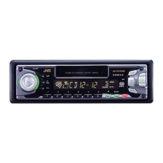
KS-FX725R
DISP
DISP
TP
TP
RDS
RDS
PTY
PTY
7
8
Safety precaution
Disassembly method
Adjustment method
Description of major ICs
x
ao
u163
y
i
COPYRIGHT
2002 VICTOR COMPANY OF JAPAN, LTD.
http://www.xiaoyu163.com
2 9
8
DAB
9
10
11
12
MO
Q Q
3
6 7
1 3
1 5
1-2
1-3
1-18
1-22
co
.
KS-FX725R
9 4
2 8
0 5
8
2 9
9 4
2 8
Area Suffix
EE ---- Russian Federation
m
9 9
9 9
No.49721
Mar. 2002
Advertisement
Table of Contents

Subscribe to Our Youtube Channel
Related Manuals for JVC KS-FX725R


Summary of Contents for JVC KS-FX725R
- Page 1 KS-FX725R 3 7 63 1515 0 SERVICE MANUAL CASSETTE RECEIVER KS-FX725R DISP DISP L 13942296513 Area Suffix EE ---- Russian Federation Contents Safety precaution Disassembly method Adjustment method 1-18 Description of major ICs 1-22 u163 No.49721 COPYRIGHT 2002 VICTOR COMPANY OF JAPAN, LTD.
-
Page 2: Safety Precaution
KS-FX725R 3 7 63 1515 0 Safety precaution Burrs formed during molding may be left over on some parts of the chassis. Therefore, pay attention to such burrs in the case of preforming repair of this system. L 13942296513 u163 http://www.xiaoyu163.com... -
Page 3: Disassembly Method
KS-FX725R 3 7 63 1515 0 Disassembly method <Main body> Removing the front panel assembly (See Fig.1) Press the eject button in the lower right part of the front panel. Remove the front panel assembly from the body. Front panel assembly Eject button Fig.1... -
Page 4: Removing The Bottom Cover
KS-FX725R 3 7 63 1515 0 Removing the heat sink (See Fig.4) Remove the three screws A on the left side of the body. Heat sink Fig.4 Joint b Removing the bottom cover (See Fig.5 , 6) Bottom cover... -
Page 5: Removing The Mainboard
KS-FX725R 3 7 63 1515 0 Removing the main board (See Fig.7 , 8) Prior to performing the following procedure, remove the front panel assembly, the front chassis assembly, the heat sink and the bottom cover. Remove the screw B, the three screws C and the... - Page 6 KS-FX725R 3 7 63 1515 0 Removing the control switch board (See Fig.10 ~ 12) Prior to performing the following procedure, remove the front panel assembly. Remove the four screws G attaching the rear cover on the back of the front panel assembly.
- Page 7 KS-FX725R 3 7 63 1515 0 REFERENCE: Prior performing following procedures, turn the mode gear on the bottom of the body until the respective part comes to the EJECT position (Refer to Fig.1). Removing the reinforce bracket (See Fig.1 and 2)
- Page 8 KS-FX725R 3 7 63 1515 0 Removing the load arm (See Fig.5) Load arm Remove the E-washer attaching the load arm. Move the load arm in the direction of the arrow and release the joint e on the cassette catch.
- Page 9 KS-FX725R 3 7 63 1515 0 Removing the side bracket assembly Side bracket assembly (See Fig.10 to 12) Joint l Remove the screw C attaching the side bracket assembly. Joint m Detach the front side of the side bracket assembly upward and pull out forward to release the joint l and m in the rear.
- Page 10 KS-FX725R 3 7 63 1515 0 Removing the pinch arm (F) assembly (See Fig.13 and 14) Remove the polywasher and pull out the pinch arm (F) assembly. Remove the compulsion spring. Polywasher Pinch arm Polywasher Pinch arm (F) assembly...
- Page 11 KS-FX725R 3 7 63 1515 0 Removing the head / tape guide (See Fig.18 and 19) Slide chassis assembly REFERENCE: It is not necessary to remove the slide chassis assembly. Remove the band attaching the wire to the head.
- Page 12 KS-FX725R 3 7 63 1515 0 Disassembling the flywheel assembly (F) (See Fig.22 and 23) Push and turn counterclockwise the spring holder (F) Flywheel assembly (F) Flywheel assembly (R) to release the three joints s on the bottom of the flywheel.
- Page 13 KS-FX725R 3 7 63 1515 0 Removing the gear base arm / gear base Gear base arm Joint w link assembly (See Fig.27 to 29) Joints v Move the gear base arm in the direction of the arrow. Hook x...
- Page 14 KS-FX725R 3 7 63 1515 0 Mode gear Mode switch actuator Removing the mode gear (See Fig.30 and 33) Remove the polywasher on the bottom and pull out the mode gear. Removing the mode switch actuator Polywasher (See Fig.30, 31 and 33) Pull out the mode switch actuator at the bottom.
- Page 15 KS-FX725R 3 7 63 1515 0 Slot f' Removing the gear base assembly / take up gear / reflector gear (See Fig.34 to 36) Push in the pin e’ of the gear base assembly on the upper side of the body and move the reflector gear toward the bottom, then pull out.
- Page 16 KS-FX725R 3 7 63 1515 0 Removing the side bracket assembly (See Fig.37 to 41) Remove the eject cam plate spring. Push the joint g‘ through the slot to remove the load rack downward. Joint g' Move the eject cam limiter in the direction of the arrow to release it from the boss h’...
- Page 17 KS-FX725R 3 7 63 1515 0 Main motor Removing the main motor assembly / assembly sub motor assembly (See Fig.42 to 44) Reduction gear (B) Belt Reduction Remove the belt at the bottom. gear (A) Remove the polywasher and pull out the mode gear.
-
Page 18: Adjustment Method
KS-FX725R 3 7 63 1515 0 Adjustment method Test instruments reqired for adjustment Standard volume position 1. Digital osclloscope(100MHz) Balance and Bass,Trable volume, Fader 2. Frequency Counter meter :Center(Indication"0") 3. Electric voltmeter Loudness,Dolby NR,Sound,Cruise:Off 4. Wow & flutter meter Volume position is about 2V at speaker output with 5. - Page 19 KS-FX725R 3 7 63 1515 0 Arrangement of adjusting & test points Cassette mechanism (Surface) Motor assembly Tape speed adjust Azimuth screw A (Forward) Playback head Azimuth screw B (Reverse) Head section view L 13942296513 Azimuth screw B Azimuth screw A...
- Page 20 KS-FX725R 3 7 63 1515 0 Arrangment of adjusting VR402:Rch VR401:Rch (Dolby NR level adj) (Dolby NR Frequency response adj) Head amplifier board section (Reverse side) C419 C418 R412 C413 C416 C414 R416 C421 C422 R414 C412 VR401 Q401...
- Page 21 KS-FX725R 3 7 63 1515 0 Item Conditions Adjustment and Confirmation methods S.Values Adjust Head Head height adjustment Test tape: azimuth Adjust the azimuth directly. When you SCC-1659 adjustment adjust the height using a mirror tape, VT703(10kHz) remove the cassette housing from the mechanism chassis.
-
Page 22: Description Of Major Ics
KS-FX725R 3 7 63 1515 0 Description of major ICs UPD178018AGC584(IC701) : System controller micon 1.Terminal Layout 24 – 1 41 – 64 2.Description Symbol Function Symbol Function KEY0 Key input 0 DOLBY O Dolby NR output H:Dolby NR ON... - Page 23 KS-FX725R 3 7 63 1515 0 HA13158A (IC941) : Power amp 1. Pin layout 2. Block diagram PVCC2 PVCC1 INVCC STBY INPUTBUFFER1 AMP1 L 13942296513 INPUTBUFFER2 AMP2 INPUTBUFFER3 AMP3 INPUTBUFFER4 AMP4 MUTE PROTECTOR (ASO SURGE, TSD) u163 1-23 http://www.xiaoyu163.com...
- Page 24 KS-FX725R 3 7 63 1515 0 CXA2559Q(IC401):Playback equalizer amplifier with music sensor 1.Pin layout 2.Blockdiagram L 13942296513 24dB 100k PBFB2 MSMODE 7k/12k PBRIN2 DRSW 300k MS MODE PNGND BIAS TAPESW PNFIN2 MUTESW MUTE TAPE EQ PBREF FWD/RVS MS ON/...
- Page 25 KS-FX725R 3 7 63 1515 0 3.Pin function CXA2559Q 2/2 Pin No. Symbol Function PBTC1 Terminal of capacity of reproduction equalizer reproduction PBOUT1 Equalizer output terminal OUTREF1 Output standard terminal TAPEIN1 Tape input terminal Power supply terminal Non connection...
- Page 26 KS-FX725R 3 7 63 1515 0 HA13164(IC961):REGULATOR 1.Terminal layout 1 2 3 4 5 6 7 8 9 10 11 12 13 14 15 2.Block diagram 100u 0.1u BATT.DET OUT ANT OUT Surge Protector 0.1u EXT OUT COMPOUT BIAS 0.1u...
- Page 27 KS-FX725R 3 7 63 1515 0 SAA6579T-X(IC761):RDS Detector 2.Pin Function 1.Terminal Layout Symbol Function QUAL RDCL Non connect QUAL RDDA RDS data output RDDA Vref OSCO Reference voltage output Vref OSC1 Multiplex signal input VDDA +5V Supply voltage for analog...
- Page 28 KS-FX725R 3 7 63 1515 0 TEA6320T-X (IC911) : E.volume 1.Pin layout 2.Block diagram VOLUME 2 MUTE 0 to 55 dB FUNCTION BALANCE OUTRR OUTLR ZERO CROSS FENDER REAR POWER DETECTOR OUTRF OUTLF SUPPLY VOLUME 1 BASS TREBLE +20 to -31 dB...
- Page 29 KS-FX725R 3 7 63 1515 0 LC75823E (IC651) : LCD Driver 1. Pin Layout & Symbol 64 63 62 61 60 59 58 57 56 55 54 53 52 51 50 49 17 18 19 20 21 22 23 24 25 26 27 28 29 30 31 32 2.
- Page 30 KS-FX725R 3 7 63 1515 0 HD74HC126FP-X (IC751) : Buffer 1.Terminal layout 3.Pin function Input Outout 2.Block diagram Output Input L 13942296513 Output Sample as Load Circuit 1 Output Sample as Load Circuit 1 Output Sample as Load Circuit 1 LB1641 (IC402) : DC motor driver 1.
- Page 31 KS-FX725R 3 7 63 1515 0 L 13942296513 u163 VICTOR COMPANY OF JAPAN, LIMITED MOBILE ELECTRONICS DIVISION PERSONAL & MOBILE NETWORK BUSINESS UNIT. 10-1,1Chome,Ohwatari-machi,Maebashi-city,371-8543,Japan 200203 (No.49721) http://www.xiaoyu163.com...
-
Page 32: Block Diagram
KS-FX725R 3 7 6 3 1 5 1 5 0 Block diagram MOTOR SWITCH MAIN TAPE END.STANDBY MOTOR HEAD CJ402 CJ403 TO SPEAKER TO CD CHANGER MOTOR METAL CONNECTOR TO REAR LINE OUT TAPE IN MODE J801 CP901 STANDBY... - Page 33 KS-FX725R 3 7 63 1515 0 < M E M O > L 13942296513 u163 http://www.xiaoyu163.com...
-
Page 34: Standard Schematic Diagrams
KS-FX725R 3 7 6 3 1 5 1 5 0 Standard schematic diagrams Receiver & System control section LA4743K IC301 J321 QAU0260-001 QNN0175-001 C323 C321 150p C324 C325 C322 R301 150p C308 2.2/50 QNB0100-002 C326 C309 R302 1/50 2.2/50 TU.R... - Page 35 KS-FX725R KS-FX725R 3 7 6 3 1 5 1 5 0 Mecha control circuit section Q403 2SB1322/RS/-T R401 Q402 DTC114EKA-X CJ403 QGF1219F1-10 0.015 C411 R418 22/16 C409 IC401 1 3 9 4 2 2 9 6 5 1 3...
- Page 36 KS-FX725R 3 7 6 3 1 5 1 5 0 LCD driver & Operation switch section LCD1 QLD0158-002 CP701 VMC0335-001 1 3 9 4 2 2 9 6 5 1 3 D601 R663 R631 COM1 R651 MA152WK-X COM2 1.5k...
-
Page 37: Printed Circuit Boards
KS-FX725R KS-FX725R 3 7 6 3 1 5 1 5 0 Printed circuit boards Main board Front board(Forward side) IC652 R652 D602 S619 D601 C653 R607 S601 R637 R608 C671 R609 R658 S609 R611 R631 C904 R639 IC901 R633... -
Page 38: Parts List
KS-FX725R 3 7 63 1515 0 PARTS LIST [ KS-FX725R ] * All printed circuit boards and its assemblies are not available as service parts. Area suffix EE --------- Russian Federation L 13942296513 - Contents - 3- 2 Exploded view of general assembly and parts list (Block No.M1) 3- 5 Cassette mechanism assembly and parts list (Block No.MP) -
Page 39: Exploded View Of General Assembly And Parts List
KS-FX725R 3 7 63 1515 0 Exploded view of general assembly and parts list Block No. L 13942296513 u163 http://www.xiaoyu163.com... - Page 40 KS-FX725R 3 7 63 1515 0 Parts list (General assembly) Block No. M1MM Item Parts number Parts name Q'ty Description Area CASSETTE MECHA 1 CDS-802JE1 --------------- SHEET FSYH4036-050 FSKL2001-004 MECHA BRACKET L FSKL2002-002 MECHA BRACKET R QYSDST2606Z SCREW 1 PCB+MECHA...
- Page 41 KS-FX725R 3 7 63 1515 0 Parts list (General assembly) Block No. M1MM Item Description Parts number Parts name Q'ty Area FSYH4036-076 SPACER VMA4652-001SS EARTH PLATE FSKL4024-001 IC BRACKET GE40103-001A REG. BRACKET GE40104-001B HEAT SINK FSKM3012-014 REAR BRACKET QYSDST2606Z...
-
Page 42: Cassette Mechanism Assembly And Parts List
KS-FX725R 3 7 63 1515 0 Cassette mechanism assembly and parts list Block No. CDS-802JE1 L 13942296513 u163 http://www.xiaoyu163.com... - Page 43 KS-FX725R 3 7 63 1515 0 Parts list (Cassette mechanism) Block No. MPMM Item Parts number Parts name Q'ty Description Area MAIN CHASSIS AS X-0802-1009S SLIDE CHASSIS A X-0802-1002S X-0802-1003S SIDE BKT ASSY X-0802-1004S CASSETTE HANGER X-0802-1005S PINCH ARM F ASS...
- Page 44 KS-FX725R 3 7 63 1515 0 Parts list (Cassette mechanism) Block No. MPMM Item Parts number Parts name Q'ty Description Area 1-0802-4007S GEAR BASE SPG 1-0802-4008S REEL DRIVER SPG COMPULSION SPG 1-0802-4013S BELT 1-0802-5001S FELT 1 7.5*18.5*1.0 1-0802-5002S 1-0802-5003S...
- Page 45 KS-FX725R 3 7 63 1515 0 Grease point 1/2 FG-84M MEA-512R MEN-223 SW-902 CFD-409 CFD-250H EP-56 SW-474B L 13942296513 u163 http://www.xiaoyu163.com...
- Page 46 KS-FX725R 3 7 63 1515 0 Grease point 2/2 L 13942296513 u163 http://www.xiaoyu163.com...
- Page 47 KS-FX725R 3 7 63 1515 0 Electrical parts list (Main board) Block No. 01 Item Parts number Parts name Remarks Area Item Parts number Parts name Remarks Area QERF1CM-107Z E CAPACITOR 100MF 20% 16V C 306 NCB21EK-104X C CAPACITOR...
- Page 48 KS-FX725R 3 7 63 1515 0 Electrical parts list (Main board) Block No. 01 Item Parts number Parts name Remarks Area Item Parts number Parts name Remarks Area D 701 UDZS5.6B-X ZENER DIODE NRS181J-330X MG RESISTOR D 702 UDZS5.6B-X...
- Page 49 KS-FX725R 3 7 63 1515 0 Electrical parts list (Main board) Block No. 01 Item Parts number Parts name Remarks Area Item Parts number Parts name Remarks Area R 341 NRSA63J-101X MG RESISTOR R 901 QRE141J-470Y C RESISTOR 47 5% 1/4W...
- Page 50 KS-FX725R 3 7 63 1515 0 Electrical parts list (Mecha control board) Block No. 02 Item Parts number Parts name Remarks Area C 401 NDC31HJ-101X C CAPACITOR C 402 NDC31HJ-101X C CAPACITOR C 403 NDC31HJ-101X C CAPACITOR C 404...
- Page 51 KS-FX725R 3 7 63 1515 0 Electrical parts list (Front board) Block No. 03 Item Parts number Parts name Remarks Area Item Parts number Parts name Remarks Area C 651 NCB31HK-103X C CAPACITOR R 651 NRSA63J-152X MG RESISTOR C 652...
- Page 52 KS-FX725R 3 7 63 1515 0 < M E M O > L 13942296513 u163 3-15 http://www.xiaoyu163.com...
-
Page 53: Packing Materials And Accessories Parts List
KS-FX725R 3 7 63 1515 0 Packing materials and accessories parts list Block No. Block No. A1~A4 L 13942296513 KIT:A6~A10 u163 3-16 http://www.xiaoyu163.com... - Page 54 KS-FX725R 3 7 63 1515 0 Parts list (Packing) Block No. M3MM Item Parts number Parts name Q'ty Description Area FSPG4002-001 POLY BAG 1 INST.BOOK QPA00801205 POLY BAG 1 KIT POLY BAG 1 HARD CASE QPA01003003 FSYH4036-068 SHEET QPC03004315P...
Need help?
Do you have a question about the KS-FX725R and is the answer not in the manual?
Questions and answers