Table of Contents
Advertisement
Advertisement
Table of Contents
Troubleshooting

Related Manuals for GEAppliances AZ75E09DAC


Summary of Contents for GEAppliances AZ75E09DAC
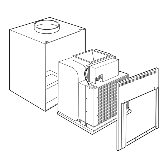
- Page 1 GE Consumer Home Services Training TECHNICAL SERVICE GUIDE Zoneline Vertical Air Conditioners Case Zoneline unit Front MODEL SERIES: AZ75E09DAC AZ75H09DAC AZ75E09EAC AZ75H09EAC AZ75E12DAC AZ75H12DAC AZ75E12EAC AZ75H12EAC AZ75E18DAC AZ75H18DAC AZ75E18EAC AZ75H18EAC PUB # 31-9089 01/02...
- Page 2 IMPORTANT SAFETY NOTICE The information in this service guide is intended for use by individuals possessing adequate backgrounds of electrical, elec- tronic, and mechanical experience. Any attempt to repair a major appliance may result in personal injury and property damage. The manufacturer or seller cannot be responsible for the interpretation of this information, nor can it assume any liability in connection with its use.
-
Page 3: Table Of Contents
Table of Contents Table of Contents Introduction ....................2 Nomenclature ..................... 3 Electrical Specifications ................4 Technical Data ..................... 6 Features and Operation ................8 ON/OFF Switch ..................8 Dip Switches................... 8 Main Board Terminal Strip ..............9 Remote Thermostat Control ..............10 Central Desk Control (CDC) .............. -
Page 4: Introduction
Introduction Case Zoneline unit Front The new Zoneline Vertical Air Conditioners are ideal for hotel/motel installations. Programmable for central desk control, electric heat, freeze sentinel, fan speed, and temperature limiting, these units allow for efficient control of power usage. The Energy Management System is also available, providing automatic comfort at peak energy efficiency. -
Page 5: Nomenclature
Nomenclature Model Number AZ 75 E 09 D A C C = Corrosion Zoneline® A = Revision D = 230/208 V Chassis Series E = 265 V BTU/hr 09 = 9000 12 = 12000 18 = 18000 E = Cooling w/Electric Resistance Heat H = Cooling w/Heat Pump and Electric Resistance Heat Model/Serial Tag Location... -
Page 6: Electrical Specifications
Electrical Specifications Wire Size and Breaker Size Warning: All wiring, including installation of the receptacle, must be in accordance with the National Electric Code, local codes, ordinances, and regulations. • Use only the wiring size recommended for single outlet branch circuit. •... - Page 7 Direct Connection 208 VAC 230 VAC 265 VAC – 5 –...
-
Page 8: Technical Data
Technical Data Heat Pump Model AZ75H12DAC DISCONNECT POWER BEFORE SERVICING IMPORTANT SAFETY NOTICE IMPORTANT - RECONNECT ALL GROUNDING DEVICES This information is intended for use by individuals possessing adequate backgrounds of electrical, electronic and mechanical experience. Any All parts of this appliance capable of conducting electrical attempt to repair a major appliance may result in personal injury and current are grounded. - Page 9 Electric Resistance Heat Model AZ75E12DAC DISCONNECT POWER BEFORE SERVICING IMPORTANT SAFETY NOTICE IMPORTANT - RECONNECT ALL GROUNDING DEVICES This information is intended for use by individuals possessing adequate backgrounds of electrical, electronic and mechanical experience. Any All parts of this appliance capable of conducting electrical attempt to repair a major appliance may result in personal injury and current are grounded.
-
Page 10: Features And Operation
Features and Operation ON/OFF Switch Warning: ON/OFF switch does not disconnect power from all circuits. Switches The ON/OFF switch is located on the electronics cover behind the front case panel. The ON/OFF switch disables all relays but does not disconnect power from all circuits. -
Page 11: Main Board Terminal Strip
Main Board Terminal Strip Caution: Improper wiring may damage the Zoneline electronics. Damage or erratic operation may result. No common busing is permitted. A separate wire pair must be run from each separate controlling switch to each individual Zoneline. ON/OFF Switch The terminal connections are located behind the front case panel. -
Page 12: Remote Thermostat Control
Remote Thermostat Control The unit is controlled by an externally mounted, remote thermostat. The Zoneline thermostat connections provide 24 VAC only. If using a digital/electronic wall thermostat, it must be set to the 24 VAC setting. Refer to the thermostat installation instructions for details. Note: Some thermostats can be programmed to energize the reversing valve in heating mode or cool mode. -
Page 13: Temperature Limiting
When a CDC switch is connected to the main board terminal strip, the unit can be turned on and off from a remote location. Up to 2000 feet of wire may be used to connect a remote CDC switch to the unit. -
Page 14: Fan Speed (Indoor Fan)
The Freeze Sentinel is enabled by a dip switch OCCUPIED and is dependant on the Room Air Sensor (kit). If the Room Air Sensor (kit) is not installed, the Freeze Sentinel will not operate. The FREEZE S dip switch must be down for Freeze Sentinel DUCT operation. -
Page 15: Energy Management System
Energy Management System The following conditions must exist for the Energy ROOM AIR SENSOR MAIN Management System to operate: BOARD • OCCUPIED dip switch is up. • Room Air Sensor (kit) is installed. MOTION SENSOR • Door Sensor (kit) is installed. •... -
Page 16: Motion Sensor (Kit)
Motion Sensor (kit) The motion sensor has a 2-wire circuit that is connected to the main board terminal strip. The motion sensor is an electronic sensor that, when motion is sensed, closes a switch (internal to the sensor), completing the motion sensor circuit. After the Energy Management System has seen Motion Sensor the door sensor circuit closed (door opened), it will... -
Page 17: Automatic Defrosting Of Indoor And Outdoor Coils
Automatic Defrosting of Indoor and Outdoor Coils During continued compressor operation, there is potential for ice to form on the indoor coil when in cool mode and for ice to form on the outdoor coil when in heat mode. The Zoneline is equipped with Automatic Defrost to eliminate this potential problem. -
Page 18: Cool Mode Operation
Cool Mode Operation Note: • Minimum compressor/fans off time is 3 minutes +/- 10 seconds. • Reversing valve is energized at all times in cool mode. Reversing valve is not de-energized when thermostat is satisfied. • Indoor and outdoor fans always operate at the same time in cool mode. Indoor fan, outdoor Indoor fan, outdoor fan, compressor,... -
Page 19: Heat Mode Operation
Heat Mode Operation Note: • Minimum compressor/fans off time is 3 minutes +/- 10 seconds. • Heat pump will not operate if outdoor thermistor sees 25 °F or less. • Heat pump and resistance heater(s) do not operate at the same time. •... -
Page 20: Slide-Out Chassis
Slide-Out Chassis WARNING: Case ground bolt at front of chassis Screws must be installed to ensure proper grounding of Cabinet Top Plate the unit. Case ground screw on left hand cabinet side plate and/or right hand cabinet side plate must be installed to ensure proper grounding of the unit. -
Page 21: Components
Components Main Board Electronics Cover To access the main board: 1. Remove 6 screws and the front panel. 2. Unplug the heater connector. WARNING: Do not touch the capacitors after the electronics cover is removed. ON/OFF Switch Caution: When removing electronics cover, pull the right side out a few inches to avoid damage to the switch wires. -
Page 22: Compressor And Capacitor
Compressor and Capacitor The Zoneline compressor is a rotary type that operates on 265/230/208 VAC. After the Compressor compressor has cycled off, it will not attempt to restart for 3 minutes /-10 seconds, regardless of the state of the thermostat. This will allow internal pressure to equalize and prevent the compressor from stalling by trying to start against high pressure in the sealed system. -
Page 23: Compressor Troubleshooting
Note: On 18000 BTU models, overload protection is internal to the compressor. COMP. SUBBOARD RUN. CAP. MOTOR O. L. P. RY202 208/230 DRIVER BOARD RY101 RY102 RY103 MAIN BOARD GEA01247 Compressor Troubleshooting Note: Minimum comp./ fans-off time is 3 min. Fan-on may be delayed. -
Page 24: Resistance Heaters
Resistance Heaters The heaters consist of three 265 VAC or 230/208 VAC resistance heating coils fastened together in a single assembly. The heaters are located behind the indoor coil and are protected against overheating by 2 thermal protectors. An L185-30 thermal protector is used as a temperature regulator. A one-shot L248 thermal protector is used as a backup in case the temperature regulating thermal protector fails (stuck closed). - Page 25 Resistance Heater Troubleshooting Note: Normal heat is provided by heat pump operation when outdoor temperature is above 25 °F. The number of heaters that operate is dependant on the Power Supply Kit used. • Tandem - 1 heater • Perpendicular - 2 heaters •...
- Page 26 To remove the resistance heaters: 1. Remove the front panel and slide the chassis forward approximately 5 in. (see Slide-Out Chassis chapter). 2. Remove electronics cover (see Main Board chapter). 3. Remove the left and right corner sheet metal panels fastened to the sides of the indoor coil. Left Corner Sheet Metal Panel Left Corner Sheet Metal Panel Right Corner Sheet Metal Panel...
-
Page 27: Indoor Fan And Capacitor
Indoor Fan and Capacitor The indoor fan is a 265/230/208 VAC, permanently lubricated motor. Indoor fan speed is selected in the following manner: When the green thermostat wire is connected to the high-speed fan (GH) terminal: DUCT SWITCH UP = HIGH FAN SPEED DUCT SWITCH DOWN = MEDIUM FAN SPEED When the green thermostat wire is connected to the low-speed fan (GL) terminal: DUCT SWITCH UP = MEDIUM FAN SPEED... - Page 28 9. Disconnect CN201 from sub board. Brace 10. Remove 3 screws from the sheet metal panel on top of the fan shroud above the wire retainer. 11. Remove the metal wire retainer and the wire harness. Fan Motor Screws Screws 7.
-
Page 29: Indoor Fan
Indoor Fan Note: Minimum comp./fan- off time is 3 minutes. Fan- on may be delayed. Does the outdoor fan spin Set thermostat to heat Remove the freely? Go to Dead Unit mode or cool mode and obstruction or troubleshooting. adjust temperature set replace the outdoor Is the outdoor fan free point so that the unit will... -
Page 30: Outdoor Fan And Capacitor
Outdoor Fan and Capacitor The outdoor fan is a single-speed, 265/230/208 VAC, permanently lubricated motor. The indoor fan and outdoor fan will operate simultaneously under normal operating conditions. However, if the heat pump is operated when high outdoor temperatures are present, the indoor coil may overheat. Should the indoor coil temperature reach 131 °F, the main board will shut the outdoor fan off . - Page 31 SUB BOARD CAPACITOR O.D. RY202 MOTOR 5 4 3 2 1 230/208 CN102 RY103 RY102 CN106 CN107 RY107 DRIVER BOARD Outdoor Fan Resistance Values MAIN BOARD 230/208 VAC Models 86 Ω Black to red wires GEA01244 Outdoor Fan Troubleshooting Note: Minimum comp./ fans-off time is 3 min.
-
Page 32: Reversing Valve
Reversing Valve The reversing valve operates on 265/230/208 VAC and is used to switch the direction of refrigerant flow. The reversing valve controls the direction of the refrigerant flow. When the reversing valve solenoid is energized, it will close the reversing valve and the unit will operate as an air conditioner. When the solenoid is de-energized, the reversing valve will open and the unit will function as a heat pump. -
Page 33: Reversing Valve Coil
SUB BOARD REV. VALVE RY202 SOLENOID CN105 230/208 RY103 RY102 CN106 CN107 RY108 DRIVER BOARD ENERGIZED = AIR CONDITIONER Reversing Valve Coil Resistance Value = 1200Ω Ω Ω Ω Ω DE-ENERGIZED = HEAT PUMP MAIN BOARD Reversing Valve Troubleshooting GEA01243 Note: Minimum compressor/fans-off time is 3 minutes. -
Page 34: Transformer
Transformer The transformer is located under the electronics cover and below the driver board. The transformer provides low voltage power to the main board, driver board and thermostat. To test the transformer: Verify line voltage is present at CN204 on sub board. If line voltage is not present, suspect building supply voltage, blown (open) fuse, a faulty sub board or a faulty driver board. -
Page 35: Thermistors
Thermistors The main control board uses input from 3 thermistors. These thermistors are located on the indoor coil, outdoor coil, and outdoor fan shroud. The main control board monitors the thermistors to determine the temperature in these areas and uses this information to make operating decisions. For the optional room air sensor (kit), see the Room Air Sensor section in the Features and Operation chapter. -
Page 36: Dead Unit Troubleshooting
Dead Unit Troubleshooting Check the ON/ OFF switch to be sure it is on. Check for 24 VAC at main board terminal strip (CN5) between Is the thermostat green fan wire (terminal illuminated? 10 or 11) and common wire (terminal 15). Voltage present? Check the fuse. - Page 37 Notes – 35 –...
-
Page 38: Schematics And Wiring Diagrams
Schematics and Wiring Diagrams Schematic (Heat Pump Models) Tandem Perpendicular Large Tandem 15 Amp. 20 Amp. 30 Amp. GEA01237 Overload is internal to compressor on 18000 BTU model. UNIVERSAL CONNECTOR FAN MOTOR FAN MOTOR CAPACITOR CAPACITOR INDOOR OUTDOOR REVERSE VALVE MOTOR MOTOR SOL. -
Page 39: Wiring Diagram
Wiring Diagram (Heat Pump Models) Tandem Perpendicular Large Tandem 15 Amp. 20 Amp. 30 Amp. GEA01237 (265V) 1 2 3 6 5 4 8 9 (230/208V) WIRING DIAGRAM 1 2 3 4 5 6 7 9 O.L.P. RY102 CN105*2 REV. VALVE SOLE. - Page 40 Schematic (Electric Resistance Heat Models) Tandem Perpendicular Large Tandem 15 Amp. 20 Amp. 30 Amp. GEA01237 Overload is internal to compressor on 18000 BTU model UNIVERSAL CONNECTOR FAN MOTOR FAN MOTOR CAPACITOR CAPACITOR INDOOR OUTDOOR REVERSE VALVE MOTOR MOTOR SOL. RUNNING COMP.
- Page 41 Wiring Diagram (Electric Resistance Heat Models) Tandem Perpendicular Large Tandem 15 Amp. 20 Amp. 30 Amp. GEA01237 (265V) 1 2 3 6 5 4 8 9 (230/208V) 1 2 3 4 5 6 7 9 O.L.P. RY102 CN105*2 REV. VALVE SOLE.
-
Page 42: Component Locator Views
Component Locator Views Outdoor Thermistor Outdoor Thermistor Ventilation Control Indoor Fan Motor Indoor Fan Motor Reversing Valve Reversing Valve Reversing Valve Solenoid Reversing Valve Solenoid Indoor Coil Thermistor Outdoor Coil Indoor Coil Thermistor Thermistor Thermostatic Drain Valve – 40 –... - Page 43 Power Cord Connector Resistance Heater Connector Outdoor Fan Motor Accumulator Accumulator Relay and Relay and Overload Cover Overload Cover Compressor Compressor Indoor Coil Outdoor Coil – 41 –...
- Page 44 Compressor Capacitor Sub Board Main Board Power Cord Connector Driver Board Fuse Indoor Fan Transformer Outdoor Fan Capacitor Capacitor – 42 –...
-
Page 45: Parts List
Parts List – 43 –... - Page 46 – 44 –...
- Page 47 – 45 –...
- Page 48 – 46 –...
- Page 49 View # Part # D e s c r i p t i o n Q u a n t i t y 1001 WJ82X10031 BOTTOM ANGLE ASS’Y 1002 WJ82X10028 CABINET TOP PLATE 1003 WJ50X10007 DUCT CONNECTOR 1004 WJ45X10017 DUCT INSULATOR 1005 WJ45X10018 DUCT INSULATOR...
- Page 50 1053 WJ79X10075 HOUSING COVER B 1054 WJ45X10024 INSULATOR 1057 WJ01X10170 MOTOR RUBBER 1058 WJ76X10108 FAN HOUSING 1059 WJ76X10109 FAN HOUSING B 1060 WJ76X10110 FAN HOUSING C 1061 WJ89X10044 BASE PAN ASS’Y 1062 WJ02X10001 PROTECTOR SPRING 1063 WJ79X10013 TERMINAL COVER 1064 WJ01X10003 GASKET WASHER 1065...
- Page 51 1096 WJ60X10002 TOP PLATE SEAL 1 1098 WJ03X10032 PROTECTOR HOLDER 1099 WJ90X10043 CABINET BACK ASS’Y 1100 WJ82X10035 FRONT PANEL ASS’Y 1101 WJ79X10078 HOUSING COVER 1102 WJ60X10005 BASE PAN SEAL 1103 WJ60X10008 FAN HOUSING SEAL A 1104 WJ60X10007 FAN HOUSING SEAL B 1105 WJ60X10006 FAN HOUSING SEAL C...
- Page 52 2020 WJ37X10027 LEAD WIRE 2021 WJ27X10001 LEAD WIRE 2022 WP23X10005 PROTECTOR, COMPRESSOR 2023 WJ28X10027 THERMISTOR ASS’Y 2024 WJ26X10039 FAN SWITCH 2025 WJ37X10028 LEAD WIRE 3000 WJ53X0128 CAP. TUBE CUT TO 11.5" 3001 WJ31X10011 COIL 3002 WJ58X10020 REVERSE VALVE 3003 WJ88X10078 CONDENSER ASS’Y 3004 WJ87X10085...
-
Page 53: Care And Cleaning
Care and Cleaning Warning: Turn the Zoneline off and disconnect the power supply before cleaning. Indoor/Outdoor Coils The exhaust coils on the Zoneline should be checked regularly. If they are clogged with dirt or soot, they may be professionally steam cleaned, a service available through your GE service center. -
Page 54: Warranty
Customer Care technician. To schedule service, Proof of the original purchase on-line, 24 hours a day, visit us at GEAppliances.com, or call date is needed to obtain service 800.GE.CARES (800.432.2737). For service in Canada, call under the warranty. - Page 55 Notes – 53 –...
Need help?
Do you have a question about the AZ75E09DAC and is the answer not in the manual?
Questions and answers