Table of Contents
Advertisement
Quick Links
ORDERING REPLACEMENT PARTS
To order replacement parts, contact the ICON Health & Fitness, Ltd. office, or write:
ICON Health & Fitness, Ltd.
Unit 4
Revie Road Industrial Estate
Revie Road
Beeston
Leeds, LS118JG
UK
Tel:
08457 089 009
Outside the UK: (44) 113 387 7133
Fax: (44) 113 387 7125
Please provide the following information when ordering replacement parts:
• the MODEL NUMBER of the product (WEEVSY3965.0)
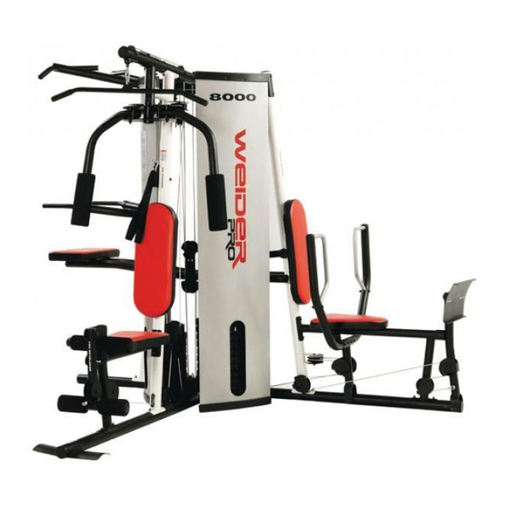
• the NAME of the product (WEIDER PRO 8000 weight system)
• the SERIAL NUMBER of the product (see the front cover of this manual)
• the KEY NUMBER and DESCRIPTION of the part(s) (see the PART LIST and EXPLODED DRAWING in the
centre of this manual)
Part No. 233300 R1105A
Printed in China © 2005 ICON IP, Inc.
Model No. WEEVSY3965.0
Serial No.
Write the serial number in the
space above for reference.
Serial Number Decal (under seat)
QUESTIONS?
As a manufacturer, we are com-
mitted to providing complete
customer satisfaction. If you
have questions, or if there are
missing parts, please call:
08457 089 009
Or write:
ICON Health & Fitness, Ltd.
Unit 4
Revie Road Industrial Estate
Revie Road
Beeston
Leeds, LS118JG
UK
email: csuk@iconeurope.com
CAUTION
Read all precautions and instruc-
tions in this manual before using
this equipment. Save this manu-
al for future reference.
USER'S MANUAL
Advertisement
Table of Contents

Related Manuals for WeiderPro 8000


Summary of Contents for WeiderPro 8000
-
Page 1: Ordering Replacement Parts
• the MODEL NUMBER of the product (WEEVSY3965.0) QUESTIONS? • the NAME of the product (WEIDER PRO 8000 weight system) As a manufacturer, we are com- • the SERIAL NUMBER of the product (see the front cover of this manual) mitted to providing complete customer satisfaction. -
Page 2: Warning Decal Placement
NOTES TABLE OF CONTENTS WARNING DECAL PLACEMENT ............. 2 IMPORTANT PRECAUTIONS . -
Page 3: Important Precautions
EXERCISE WEIGHT SETS REPS IMPORTANT PRECAUTIONS MONDAY Date: WARNING: To reduce the risk of serious injury, read the following important precautions before using the weight system. 1. Read all instructions in this manual and all 9. Always wear athletic shoes for foot protec- warnings on the weight system before using tion while exercising. -
Page 4: Before You Begin
Thank you for selecting the versatile WEIDER ® reading this manual, see the front cover of this manual. 8000 weight system. The weight system offers an To help us assist you, please note the product model impressive array of weight stations designed to devel- number and serial number before calling. -
Page 5: Assembly
Rest for a short period of time after each set. The slowly as you stretch and do not bounce. Ease into ASSEMBLY ideal resting periods are: each stretch gradually and go only as far as you can • Rest for three minutes after each set for a muscle without strain. -
Page 6: Frame Assembly
Frame Assembly EXERCISE GUIDELINES THE FOUR BASIC TYPES OF WORKOUTS PERSONALIZING YOUR EXERCISE PROGRAM Before beginning assembly, make sure you understand the information in the boxes on Muscle Building Determining the exact length of time for each workout, page 5. See the PART IDENTIFICATION To increase the size and strength of your muscles, as well as the number of repetitions or sets completed, CHART in the center of this manual for help... - Page 7 5. Attach the Rear Upright (6) to the Rear Base (3) MAINTENANCE with the two indicated M8 x 75mm Carriage Bolts (84) and two M8 Nylon Locknuts (115). Do not tighten the Locknuts yet. Make sure all parts are properly tightened each time the weight system is used. Replace any worn parts imme- diately.
- Page 8 7. Attach the Left Upright (5) to the Left Base (2) with the two indicated M8 x 75mm Carriage Bolts Lat Cable (71) (84) and two M8 Nylon Locknuts (115). Do not Length: 16 feet tighten the Locknuts yet. 8. Hold the Left Top Frame (8) between the Left Upright (5) and the Rear Upright (6).
-
Page 9: Cable Diagrams
10. Attach two Weight Guides (24) to the Right Base CABLE DIAGRAMS (1) with an M10 x 155mm Bolt (130), two M10 Washers (116), and an M10 Nylon Locknut (114). The cable diagrams below show the approximate length and the proper routing of the Right Stack Cable (68), Slide two Weight Bumpers (65) onto the Weight the Press Cable (69), the Leg Lever Cable (70), the Lat Cable (71), and the Ab Cable (72). -
Page 10: Weight Resistance Chart
11. Attach a Rear Shroud (25) to the Right Base (1) WEIGHT RESISTANCE CHART with two M6 x 12mm Screws (124) and two M6 Long Washers (132). Make sure that the long holes Holes in the Shroud are near the top. The chart below shows the approximate weight resistance at each exercise station. - Page 11 ADJUSTING THE BACKREST 13. Attach the four Weight Guides (24) to the Right Top Frame (7) with four M10 x 38mm Screws (82) To adjust the position of the Left Backrest (33), disen- and four M10 Washers (116). gaging the Knob (121) from the Left Upright (5) and move the Backrest to the desired position.
- Page 12 Arm Assembly ADJUSTMENTS Tube 17. Grease an M10 x 108mm Bolt (99). Orient the This section explains how to adjust the weight system. See the EXERCISE GUIDELINES on page 31 for important Press Frame (13) so that the welded tube is on information about how to get the most benefit from your exercise program.
-
Page 13: Cable Diagrams
70. Press the two Shroud Covers (26) onto the Right 20. Attach the Leg Bumper (76) to the Right Seat Front Shroud (15), which has a shorter opening Frame (9) with an M4 x 16mm Self-tapping Screw than the Left Front Shroud (not shown). Attach (113) and an M4 Washer (131). -
Page 14: Lat Cable (71)
66. Attach the Left Backrest (33) to the Backrest Cable Assembly Frame (27) with two M6 x 16mm Screws (85), an M6 x 35mm Screw (139), and an M6 Washer (132). 23. See the CABLE DIAGRAMS on pages 28 and 29 as you assemble the cables and to identify Slide the Backrest Frame (27) into the Left the cables. -
Page 15: Seat Assembly
62. Wrap the Press Cable (69) under a 90mm Pulley 28. Route the Lat Cable (71) over a 90mm Pulley (39). Attach the Pulley, two M10 Washers (116), (39) and down through the Left Top Frame (8). and two Half Finger Guards (42) to the Left Base Attach the Pulley inside the Top Frame with an (2) with an M10 x 52mm Bolt (102) and an M10 M10 x 80mm Bolt (111), two M10 Washers (116),... - Page 16 33. Wrap the Ab Cable (72) over a “V”-pulley (40). 57. Wrap the Press Cable (69) under a “V”-pulley Attach the “V”-pulley, a Cable Trap (49), an M10 (40). Attach the “V”-pulley, two Half Finger Guards Washer (116), and two Full Finger Guards (43) to (42), and two M10 Washers (116) to the Leg the Right Upright (4) with an M10 x 61mm Bolt 40 116...
-
Page 17: Leg Lever Cable (70)
52. Wrap the Right Stack Cable (68) around a 90mm 37. Grease the shoulder of an M8 x 22mm Shoulder Bolt (88). Attach the Ab Cable (72) to the bracket Pulley (39). Attach the Pulley and a Small Cable on the Right Upright (4) with the Bolt and an M8 Trap (48) to the Right Top Frame (7) with an M10 Nylon Locknut (115). - Page 18 42. Wrap the Leg Lever Cable (70) under a 90mm 47. Route the Leg Lever Cable (70) over a 90mm Pulley (39). Attach the Pulley and two Half Finger Pulley (39) and down through the Right Top Guards (42) to the Right Base (1) with an M10 x Frame (7).
-
Page 19: Part Identification Chart
PART IDENTIFICATION CHART M6 Locknut (135) M10 x 77mm Bolt (133) See the drawings below to identify small parts used in assembly. The number in parentheses by each drawing is the key number of the part, from the PART LIST in the center of this manual. Note: Some small parts may have been pre-attached. - Page 20 Key No. Qty. Description Key No. Qty. Description PART LIST—Model No. WEEVSY3965.0 R1105A M6 x 22mm Screw M10 x 155mm Bolt Key No. Qty. Description Key No. Qty. Description Chain M4 Washer M10 x 80mm Bolt M6 Washer M4 x 12mm Self-tapping Screw M10 x 77mm Bolt Right Base 50mm Round Inner Cap...
- Page 21 EXPLODED DRAWING A—Model No. WEEVSY3965.0 EXPLODED DRAWING B—Model No. WEEVSY3965.0 R1105A R1105A 91 117 39 42 39 42...
- Page 22 EXPLODED DRAWING C—Model No. WEEVSY3965.0 EXPLODED DRAWING D—Model No. WEEVSY3965.0 R1105A R1105A 85 116...
Need help?
Do you have a question about the 8000 and is the answer not in the manual?
Questions and answers