
Related Manuals for Velleman VMB4RY


Summary of Contents for Velleman VMB4RY
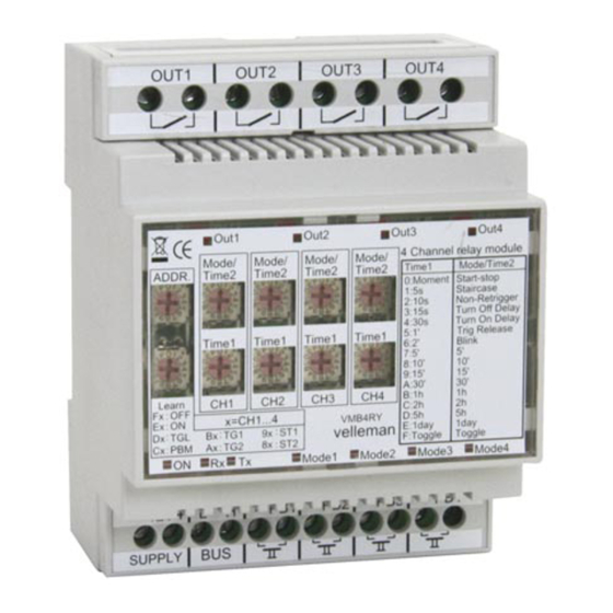
- Page 1 VMB4RY 4 channel relay module for VELBUS system VMB1RY PROTOCOL – edition 1 _ rev4...
- Page 2 Binairy format: <SOF-SID10...SID0-RTR-IDE-r0-DLC3...0-DATABYTE1...DATABYTEn-CRC14...CRC1-CRCDEL-ACK-ACKDEL- EOF7...EOF1-IFS3...IFS1> bits Description Start Of Frame (always 0) SID10 & SID9 Priority (00: highest … 11: lowest priority) SID8…SID1 Address SID0 Always 0 Remote Transmit Request Identifier Extension (always 0) reserved (always 0) DLC3…DLC0 Data Length Code (0…8) Databyte1 Command Databyte2...
- Page 3 • Write memory data • Write memory data block (4 bytes) (Build 0742 or higher) Transmits the push button & relay switch status: (Build 0817 or higher) SID10-SID9 = 00 (highest priority) SID8...SID1 = Address set by hex switches RTR = 0 DLC3...DLC0 = 4 databytes to send DATABYTE1 = COMMAND_PUSH_BUTTON_STATUS (H’00’) DATABYTE2 = Local mode push buttons just pressed / relays just switched on (1 = just pressed / switched on)
- Page 4 Transmit: Sets LEDs on a push button module: SID10-SID9 = 11 (lowest priority) SID8...SID1 = Address of the push button module for setting LEDs on RTR = 0 DLC3...DLC0 = 2 databytes to send DATABYTE1 = COMMAND_SET_LED (H’F6’) DATABYTE2 = LED bit numbers (1 = set LED) Transmit: Blinks LEDs slowly on a push button module: SID10-SID9 = 11 (lowest priority) SID8...SID1 = Address of the push button module for slowly blinking LEDs...
- Page 5 Transmits the relay status: SID10-SID9 = 11 (lowest priority) SID8...SID1 = Address set by hex switches RTR = 0 DLC3...DLC0 = 8 databytes to send DATABYTE1 = COMMAND_RELAY_STATUS (H’FB’) DATABYTE2 = Relay bit number Contents Relay number B’00000001’ Channel 1 B’00000010’...
-
Page 6: Dlc3...Dlc0 = 8 Databytes To Send
Transmits the module type: SID10-SID9 = 11 (lowest priority) SID8...SID1 = Address set by hex switches RTR = 0 DLC3...DLC0 = 8 databytes to send DATABYTE1 = COMMAND_MODULE_TYPE (H’FF’) DATABYTE2 = 4_CHANNEL_RELAY_MODULE_TYPE (H’08’) DATABYTE3 = Channel 1 hex switch setting (low nibble = Time1 / high nibble = Mode/Time2 setting) DATABYTE4 = Channel 2 hex switch setting (low nibble = Time1 / high nibble = Mode/Time2 setting) DATABYTE5 = Channel 3 hex switch setting (low nibble = Time1 / high nibble = Mode/Time2 setting) DATABYTE6 = Channel 4 hex switch setting (low nibble = Time1 / high nibble = Mode/Time2 setting) -
Page 7: Relay Number Channel
Transmits the first part of the relay name: SID10-SID9 = 11 (lowest priority) SID8...SID1 = Address set by hex switches RTR = 0 DLC3...DLC0 = 8 databytes to send DATABYTE1 = COMMAND_RELAY_NAME_PART1 (H’F0’) DATABYTE2 = Relay bit number Contents Relay number B’00000001’... -
Page 8: Channel
Transmits the first part of the local mode push button name: (Build 0817or higher) SID10-SID9 = 11 (lowest priority) SID8...SID1 = Address set by hex switches RTR = 0 DLC3...DLC0 = 8 databytes to send DATABYTE1 = COMMAND_PUSH_BUTTON_NAME_PART1 (H’F0’) DATABYTE2 = Push button identifier bit Contents Push button number B’00010000’... -
Page 9: Channel
‘Push button status’ received: SID10-SID9 = 00 (highest priority) SID8...SID1 = Address of the push button module RTR = 0 DLC3...DLC0 = 4 databytes received DATABYTE1 = COMMAND_PUSH_BUTTON_STATUS (H’00’) DATABYTE2 = Push buttons just pressed (1 = just pressed) DATABYTE3 = Push buttons just released (1 = just released) DATABYTE4 = Push buttons long pressed (1 = longer than 0.85s pressed) ‘Clear LED’... -
Page 10: Channel
‘Start relay timer’ command received: SID10-SID9 = 00 (highest priority) SID8...SID1 = Address set by hex switches RTR = 0 DLC3...DLC0 = 5 databytes received DATABYTE1 = COMMAND_START_RELAY_TIMER (H’03’) DATABYTE2 = Relay bit number Contents Relay number B’00000001’ Channel 1 B’00000010’... -
Page 11: Vmb1Ry Protocol – Edition 1 _ Rev4
‘Module type request’ command received: SID10-SID9 = 11 (lowest priority) SID8...SID1 = Address set by hex switches RTR = 1 DLC3...DLC0 = 0 databytes received ‘Relay and/or push button name request’ command received (Build 0817 or higher): SID10-SID9 = 11 (lowest priority) SID8...SID1 = Address set by hex switches RTR = 0 DLC3...DLC0 = 2 databytes received... - Page 12 ‘Write data to memory’ command received: SID10-SID9 = 11 (lowest priority) SID8...SID1 = Address set by hex switches RTR = 0 DLC3...DLC0 = 4 databytes received DATABYTE1 = COMMAND_WRITE_DATA_TO_MEMORY (H’FC’) DATABYTE2 = High memory address High address Memory bank H’00’ For channel 1 data H’01’...
- Page 13 Memory map Build 0812 or lower: Address Contents Address Contents H’0000’ Push button module address H’0001’ Clear push button 1 bit numbers for channel 1 H’001C’ Push button module address H’001D’ Clear push button 15 bit numbers for channel 1 H’001E’...
- Page 14 Address Contents Address Contents H’0200’ Push button module address H’0201’ Clear push button 1 bit numbers for channel 3 H’021C’ Push button module address H’021D’ Clear push button 15 bit numbers for channel 3 H’021E’ Push button module address H’022F’ Set push button 1 bit numbers for channel 3 H’023A’...
- Page 15 Memory map Build 0817 or higher: Address Contents Address Contents H’0000’ Push button module address H’0001’ Clear push button 1 bit numbers for channel 1 H’001A’ Push button module address H’001B’ Clear push button 14 bit numbers for channel 1 H’001C’...
- Page 16 Address Contents Address Contents H’0200’ Push button module address H’0201’ Clear push button 1 bit numbers for channel 3 H’021A’ Push button module address H’021B’ Clear push button 14 bit numbers for channel 3 H’021C’ Push button module address H’022D’ Set push button 1 bit numbers for channel 3 H’0236’...
Need help?
Do you have a question about the VMB4RY and is the answer not in the manual?
Questions and answers