Table of Contents
Advertisement
Quick Links
Advertisement
Table of Contents

Related Manuals for NF WF1946B

Summary of Contents for NF WF1946B
- Page 1 MULTIFUNCTION SYNTHESIZER WF1946B INSTRUCTION MANUAL NF Corporation...
- Page 3 DA00012506-002 WF1946B MULTIFUNCTION SYNTHESIZER Instruction Manual...
-
Page 5: Foreword
Foreword Thank you very much for procuring the WF1946B MULTIFUNCTION SYNTHESIZER. At the outset, please take a few minutes to read the Safety Precautions indicated in this manual in order to use this equipment safely and correctly. ● Warning and Caution notices The following Warning and Caution notices appear in this manual. -
Page 6: Safety Precautions
Do not use this equipment in the presence of flammable gas. There is danger of fire and explosion. ● Do not remove covers This equipment contains dangerously high voltages. Do not remove external covers. Refer all internal inspection and service to a qualified service technician who fully understands the hazards. WF1946B... - Page 7 Appears in the text and on the product to advise risk of damage to the product. Ground indication: Indicates connector housing and signal ground is connected to a chassis ground. Indicates power switch on state. Indicates power switch off state. WF1946B...
-
Page 9: Table Of Contents
Sweep stop/restart input (SWEEP PAUSE IN) ······················································· 3-10 Sweep X-drive output (SWEEP X-DRIVE OUT) ··················································· 3-10 Sweep marker output (SWEEP Z-MARKER OUT) ················································ 3-11 External add input (EXT ADD IN) ········································································· 3-11 External AM input (EXT AM IN)··········································································· 3-12 Contents 1 WF1946B... - Page 10 Phase modulation (PM)··························································································· 4-53 Pulse width modulation (PWM)·············································································· 4-56 4.4 Arbitrary Waveform········································································································ 4-60 Arbitrary waveform (ARB) ····················································································· 4-60 4.5 Selecting waveforms of synchronous signals (SYNC OUT) ··········································· 4-65 Procedure ················································································································ 4-65 When the oscillation mode is BURST····································································· 4-65 Contents 2 WF1946B...
- Page 11 Fixed frequency ratio (RATIO)··············································································· 5-27 Section 6 Troubleshooting······················································································································ 6-1 6.1 Error message ················································································································· 6-2 Power on error ········································································································ 6-2 Operation error········································································································ 6-3 6.2 Suspected failure············································································································· 6-6 In case of abnormality····························································································· 6-6 Section 7 Maintenance ··························································································································· 7-1 7.1 Outline ···························································································································· 7-2 Contents 3 WF1946B...
- Page 12 8.1 Waveform and output characteristics ·············································································· 8-2 8.2 Output voltage ················································································································ 8-4 8.3 Other functions ··············································································································· 8-5 8.4 Initialized settings··········································································································· 8-11 8.5 Remote control ··············································································································· 8-12 8.6 Options ··························································································································· 8-13 8.7 General items ·················································································································· 8-14 External drawing····································································································· 8-16 Index···························································································································································· Index1 Contents 4 WF1946B...
-
Page 13: Section 1 Overview
Section 1 Overview 1.1 Features ·····················································································································1-2 1.2 Operating principles···································································································1-3 Block diagram····································································································1-3 1.3 Function outline·········································································································1-4 Description of main function··············································································1-4 Function tree ······································································································1-5 WF1946B... -
Page 14: Features
1.1 Features The WF1946B Wave Factory is a multifunctional synthesizer based on the direct digital synthesizer (DDS) system. Although the WF1946B is two-channel device, the series also includes a single-channel WF1945B, a single-channel WF1943B with basic functions, and a two-channel WF1944B with basic functions. -
Page 15: Operating Principles
The lowpass filter (LPF) smoothes the stepped D/A output signal. Amplitude control is set by the gain control. DC offset is produced by the offset D/A converter and the output amplifier adds and amplifies the output signal. The attenuator (ATT) selects the output range by 1/10 attenuation on/off. WF1946B... -
Page 16: Function Outline
The units can be expressed by up to 4 desired characters. • Setting store and recall The settings for frequency, amplitude, etc., can be stored and recalled. The WF1946B is capable of 10 combinations store/recall. • Computer control Remote control (GPIB or USB) enables remote control from a personal computer. -
Page 17: Function Tree
Linear, logarithmic Modulation Modulation type Frequency, amplitude, DC offset, phase, duty Modulation waveform Noise Waveform /arbitrary waveform (ARB) (50 % fixed duty)/ (variable duty)/ Voltage Output range Amplitude setting DC offset setting High level setting Low level setting (continued) WF1946B... - Page 18 Output mode setting at power on Sync out, sweep period output Trigger, gate, sweep start input Sweep stop, restart input Sweep X-DRIVE output Sweep marker output External add input External AM input 1991 synchronous operation option 1992A digital output option WF1946B...
-
Page 19: Section 2 Preparation
Safety check·······································································································2-2 Unpacking and repacking···················································································2-2 Options ··············································································································2-3 2.2 Power source and grounding······················································································2-4 Grounding··········································································································2-4 Line filter ···········································································································2-4 Power source······································································································2-4 Power supply fuse ······························································································2-6 2.3 Installation ·················································································································2-7 Cautions·············································································································2-7 Installation conditions ························································································2-7 Panel and case cleaning······················································································2-7 2.4 Conformable standards ······························································································2-8 2.5 Calibration ·················································································································2-9 WF1946B... -
Page 20: Check Before Using
2.1 Check before using Safety check Before using the WF1946B, refer to the Safety precautions of this manual and confirm safety. Also, before connecting the power, refer to Section 2.2 Power source and grounding and thoroughly check the safety. Unpacking and repacking First, inspect the equipment for possible damage in shipping. -
Page 21: Options
The required number of cables is one less than the total number of connected units. 1992A digital output option If ordered, this option is installed at time of shipment. The following accessory cable is also provided. Supplied accessory Digital output cable (1 meter)······························································ 1 WF1946B... -
Page 22: Power Source And Grounding
For your safety, be sure to ground the device. Fuse To power switch Chassis Power source ! CAUTION Be sure to observe the following in order to prevent damage to the equipment. Confirm the power source voltage is within the range specified for the WF1946B. WF1946B... - Page 23 115V 230V Before using the WF1946B with a source voltage that differs from the factory setting, be sure to contact the sales representative of NF Corporation. Make sure that the power switch is off before connecting the power cable. Also, after switching power off, wait at least five seconds before switching the power on again.
-
Page 24: Power Supply Fuse
There is risk of fire from an improperly rated fuse. Be sure to disconnect the power cable before replacing the fuse. Fuse: Time lag 2 A (100/115 V) or time lag 1 A (230 V) 250 V, φ5.2 × 20 mm The specified rating of a fuse changes depending on the power source voltage. WF1946B... -
Page 25: Installation
Near pulse type noise sources Also, when using, provide separation between the power cords and signal cables of the WF1946B and those of other equipment. Operating error can occur if the power cords and signal cables are too close. Cable routing requires particular attention when installing in a rack or other facility. -
Page 26: Conformable Standards
2.4 Conformable standards The WF1946B conforms to the following standards. Safety: EN 61010-1: 2001 EMC: EN 61326: 1997/A1: 1998/A2: 2001 However, the performance criteria for the following standards are as follows: EN61000-4-2(1995):C EN61000-4-4(1995), EN61000-4-5(1995), EN61000-4-11(1994):B The phase synchronization (φSYNC) operation may be required because the phase difference between channels is caused by the electrostatic discharge. -
Page 27: Calibration
2.5 Calibration Section 7.3 the Performance tests are recommended at least once a year. These should also be conducted before important tests and measurements. WF1946B... -
Page 29: Section 3 Basic Operation
Amplitude setting·······························································································3-30 DC offset setting ································································································3-31 Phase setting ······································································································3-32 Output on/off ·····································································································3-33 Operation tree ····································································································3-34 ・Following is an example of the display when using this section. Fully lighted (bold) Flashing PRESET SYSTEM:RANGE PRESET USER-UNIT Fully lighted (bold) Dimly lighted WF1946B... -
Page 30: Panel Description
3.1 Panel description This section describes the indications and functions of the front and rear panels of the WF1946B. WF1946B... -
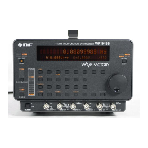
Page 31: Front Panel
3.1 Panel description Front panel WF1946B... -
Page 32: Rear Panel
3.1 Panel description Rear panel WF1946B... -
Page 33: Input And Output Connectors
50 Ω input impedance or terminating the input at 50 Ω. ・Setting and output voltages The setting voltage display and actual output voltage (load terminal voltage) differ according to the load resistance. “5.5 Other settings (■LOAD function (equalize setting and output values))”, cf. WF1946B... -
Page 34: Sync Signal Output (Sync Out)
Although 50 Ω termination is possible, the high level voltage is reduced by about half. ・ Waveform and sync signal output relationship (Waveform phase definition) (1) Continuous oscillation mode (NORMAL) ① Sinewave WF1946B... - Page 35 1.0 ns rms and below (Stop level off and 1 MHz and above) the FUNCTION OUT waveform when stop level is On or 100 kHz and below. ④ Squarewave (variable duty) (Phase definition) Approximately 25 ns p-p jitter is also produced in the FUNCTION OUT waveform. WF1946B...
- Page 36 High level when modulation waveform phase is above 0 and less than 180 degrees. Low level above 180 and below 360 degrees. FUNCTION OUT (Internal modulation waveform) SYNC OUT (5) Noise mode (NOISE) Digital (binary) noise source output. (6) DC mode (DC) Always high level. WF1946B...
-
Page 37: Trigger/Sweep Input (Trig/Sweep In)
However, contact chatter from a mechanical switch or relay can prevent normal operation. Also, chattering will prevent normal operation when the oscillation mode is triggered gate. Avoid using a logic IC circuit having a power supply voltage higher than +5 V such as example (c) for the WF1946B input WF1946B... -
Page 38: Sweep Stop/Restart Input (Sweep Pause In)
0 to +5 V (open) Output impedance : Approx. 1 kΩ Recommended load : Above 10 kΩ Ground : Connected to chassis ground ! CAUTION Avoid shorting the output or applying an external signal. The unit can be damaged. 3-10 WF1946B... -
Page 39: Sweep Marker Output (Sweep Z-Marker Out)
50 Ω Input impedance : External add frequency : Up to 10 MHz Ground : Connected to signal ground (floating from chassis) ! CAUTION Do not apply a signal exceeding the above voltage. The unit can be damaged. 3-11 WF1946B... -
Page 40: External Am Input (Ext Am In)
25 ns (clock period) + 8 (secondary) ns (phase sync pulse delay) = 33 ns. The WF1945B, WF1946B, WF1945A, WF1946A, WF1965, WF1966, WF1945 (1945), WF1946 (1946), and WF1956 (1956) equipped with the 1991 can be connected. - Page 41 • If possible, simultaneously switch off all products that are connected by the sync transfer cables. If simultaneous switch-off is not possible, switch off products in succession from the slave (secondary, tertiary) side to the master (primary) side. 3-13 WF1946B...
-
Page 42: Digital Output (Digital Out) (1992A Option)
Connect GND to all target signal grounds. Lease unused signal lines open. When the drain line is connected to the target signal ground, the WF1946B signal grounds (FUNCTION OUT, SYNC OUT, EXT ADD IN, EXT AM IN) are grounded to chassis. - Page 43 Digital output is undefined when the oscillation mode is NOISE or DC. • Except for the following cases, data corresponding to the waveform (FUNCTION) is output as digital output: (duty 50% fixed): Data corresponding to is output. (variable duty): Data to be output is undefined. 3-15 WF1946B...
-
Page 44: Basic Operation
(lower PRESET flashes). PRESET SYSTEM:RANGE PRESET USER-UNIT 4 ENTER ② Press the key (upper PRESET flashes). ENTER ENTER ③ Again press the key to initialize. To return without initializing, before pressing EXIT press the key twice. 3-16 WF1946B... - Page 45 When both channels SWEEP MODE MODE → SWEEP, START 1000 Hz TYPE=FREQ STOP 10000 Hz CENTER 5500 Hz SPAN 9000 Hz MARKER 5000 Hz MODE → SWEEP, START 0.1Vp-p TYPE=AMPTD STOP 1Vp-p CENTER 0.55Vp-p SPAN 0.9Vp-p MARKER 0.5Vp-p Continued next page 3-17 WF1946B...
- Page 46 DEVIATION TYPE=PWM ENTRY→FREQ 1000 Hz ENTRY→AMPTD 0.1 Vp-p ENTRY→OFFSET ENTRY→PHASE 0 deg ENTRY→WIDTH 0.0005 s In case of FUNCTION= ENTRY→DUTY 50 % In case of FUNCTION= ENTRY→PERIOD 0.001 s ENTRY→HIGH 0.05 V −0.05 V ENTRY→LOW Continued next page 3-18 WF1946B...
- Page 47 Continued from previous page Key operation Menu Initial settings Remarks ENTRY→ΔFREQ 0 Hz When CHANNEL MODE=2 TONE ENTRY→RATIO 0000001:0000001 When CHANNEL MODE=RATIO FUNCTION SYSTEM RANGE AUTO LOAD OPEN (50 ohms at SET) EXT-AM EXT-ADD DUTY-VALID IMMED SYNC OUT STATE 3-19 WF1946B...
-
Page 48: Channel Mode Selection (Channel Mode)
: CH1 and CH2 operate at the same frequency, amplitude and DC offset, but at opposite waveforms (reverse phase). In this mode, amplitude, DC offset, output range, output on/off, phase, frequency sweep and frequency modulation settings are copied from CH1 to CH2. 3-20 WF1946B... - Page 49 This completes channel mode change. Other: ・ When the channel mode is changed, the CH2 setting is determined on the basis of the CH1 setting. ・ The channel mode and setting relationships “3.3 Basic operation (■Channel modes and settings)”, cf. 3-21 WF1946B...
-
Page 50: Channel Modes And Settings
○ △ ○ ▲ ○ ▲ ○ △ SPAN ○ △ ○ △ ○ ▲ ○ △ MARKER ○ ○ ○ ○ ○ ○ ○ △ MKT→CTR ○ △ ○ △ ○ △ ○ △ Continued next page 3-22 WF1946B... - Page 51 ○ ○ ○ △ SYNC OUT ○ ○ ○ ○ ○ ○ ○ △ CH 1/CH 2 ○ ○ ○ ○ ○ ○ ○ × CH 1, CH 2 OUT ○ ○ ○ ○ ○ ○ ○ △ 3-23 WF1946B...
-
Page 52: Channel Selection
This selects the setting and display for CH1. Each time the key is pressed, the setting and display change as follows: CH1 → CH2 → CH1 BOTH → CH2 BOTH → CH1… Other: The channel cannot be selected when the channel mode is DIFF. 3-24 WF1946B... -
Page 53: Oscillation Mode Selection
In this example, first set to DC, then to continuous (NORMAL). MODE ① Press the key, then the key to set the DC mode. The DC STATUS lamp lights. MODE NORMAL ② Press the key, then the key to set the NORMAL mode. The NORMAL STATUS lamp lights. 3-25 WF1946B... -
Page 54: Waveform Selection
When the pulse width is 100 ns or less, jitter becomes relatively larger compared with the pulse width, and a warning message is displayed. If the pulse width falls below 25 ns, pulses may disappear. If the pulse width falls below 100 ns, jitter becomes relatively larger compared with the pulse width. 3-26 WF1946B... - Page 55 Even though DUTY-VALID is set to CYCLE, extra pulses may be output if the frequency or phase is changed. Operation when DUTY-VALID: IMMED The setting will be reflected at the same time that the duty changes Operation when DUTY-VALID: CYCLE The setting will be reflected in the subsequent cycles Duty change 3-27 WF1946B...
- Page 56 0.0100% to 99.9900%. The waveform cannot be selected in the following cases. ・ Oscillation mode is NOISE or DC. ・ TYPE is DUTY in SWEEP oscillation mode. ・ TYPE is PWM in MODU oscillation mode. 3-28 WF1946B...
-
Page 57: Frequency Setting
(e.g., 50 Hz), press ENTER key directly after entering the frequency. “5.2 Units”, cf. ・ The frequency generating period can also be set. “5.1 Convenient Settings (■Frequency [Hz] setting by period [s])”, cf. 3-29 WF1946B... -
Page 58: Amplitude Setting
・ Units other than Vp-p can also be set. “5.2 Units (■Amplitude units change)”, cf. ・ Can also be set by waveform high level and low level. “5.1 Convenient Settings (■Amplitude and DC offset setting by high and low level)”, cf. 3-30 WF1946B... -
Page 59: Dc Offset Setting
④ After setting, press the key to release the setting mode. Other: ・ Can also be set by waveform high level and low level. “5.1 Convenient Settings (■Amplitude and DC offset setting by high and low level)”, cf. 3-31 WF1946B... -
Page 60: Phase Setting
① Press the key, then the key. ② Select the digit to be changed with the keys. MODIFY ③ Turn the dial to set the flashing digit. EXIT ④ After setting, press the key to release the setting mode. 3-32 WF1946B... -
Page 61: Output On/Off
The lamp lights when on, extinguishes when off. Other: Except when the channel mode is DIFF, each channel operates independently. In the DIFF mode, the channel outputs are coupled (i.e., by operating either CH1 OUT or CH2 OUT, both channel outputs are set on/off). 3-33 WF1946B... -
Page 62: Operation Tree
MARK (Number of cycles signal present) * For TYPE: BURST/TRIG SPACE (Number of cycles signal not present) * For TYPE: BURST STOP-LEVEL (Stop level) OPER-COMMON (Simultaneous operation of both channels) * When the same TYPE is set for both channels BURST Operation MAN TRIG 3-34 WF1946B... - Page 63 * When modulating both channels MODU Operation START STOP ENTRY Main operation FREQ AMPTD OFFSET PHASE DUTY WIDTH PERIOD HIGH △FREQ RATIO * DUTY/WIDTH for FUNCTION: FREQ is for CHANNEL MODE: 2TONE RATIO is for CHANNEL MODE: RATIO 3-35 WF1946B...
- Page 64 COPY 2 → 1 (Copy a setting) EXT-AM (External AM selection) EXT-ADD (External addition selection) φ SYNC (Phase synchronization) DUTY-VALID (Duty) POWER-ON (Output state selection at power-on) REMOTE (Remote control menu) INTERFACE (Interface) ADDRESS/ID (GPIB address/USB ID) DELIMITER (GPIB delimiter) OPTION (Option menu) 3-36 WF1946B...
- Page 65 Setup memory menu STORE (Save setup memory) RECALL (Call setup memory) CLEAR (Clear setup memory) (Release remote state) LOCAL UNDO (Cancel setting) EXIT (Move to menu immediately above) ENTER (Accept input value) Numeric input (keypad) µ Numeric modification (Modify) MODIFY 3-37 WF1946B...
-
Page 67: Section 4 Applications
4.6 Output waveforms for sweeping and modulation ·······················································4-68 4.7 Equivalent noise bandwidth ·······················································································4-70 ・Following is an example of the display when using this section. Fully lighted (bold) Dimly lighted BURST TRIG GATE 4 BURST:TYPE MARK SPACE STOP―LEVEL Fully lighted Flashing Dimly lighted (bold) WF1946B... -
Page 68: Burst Oscillation
③ Press the key, then produce the following display with the keys (BURST flashes). BURST TRIG GATE 4 BURST:TYPE MARK SPACE STOP―LEVEL EXIT ④ This sets the burst oscillation type to burst. Press the key once to exit type setting. WF1946B... - Page 69 (0.5 cycle units). In this example, the setting is 1.5 cycles. EXIT ④ After setting, press the key once to release space cycle setting. (4) Set STOP-LEVEL ① Use the keys to produce the following display (STOP-LEVEL flashes). OFF BURST:TYPE MARK SPACE STOP―LEVEL WF1946B...
- Page 70 Stop 1 wave Oscillation start Start phase: -90° • Burst oscillation setting items (BURST menu) TYPE: BURST MARK (oscillation cycle) [cycle] SPACE (cycle when oscillation stops) [cycle] STOP-LEVEL [OFF, ON[%]] PHASE (phase when oscillation starts) [deg] * ENTRY menu WF1946B...
-
Page 71: Burst Oscillation (Type: Trigger)
③ Press the key, then produce the following display with the keys (TRIG flashes). BURST TRIG GATE 4 TRIG:TYPE SOURCE DELAY MARK 4 EXIT ④ This sets the burst oscillation type to trigger. Press the key to exit type setting. WF1946B... - Page 72 TRIG:TYPE SOURCE DELAY MARK 4 ENTER ② Press the key. MODIFY ③ Set the delay time with the keypad or dial. For example, set to 1 ms. EXIT ④ After setting, press the key once to release delay time setting. WF1946B...
- Page 73 In this example, the setting is -50 %. The stop level is the percentage with respect to the maximum positive (+100 %) and negative (-100 %) amplitude. EXIT ④ After setting, press the key to release the setting mode. WF1946B...
- Page 74 • To generate the trigger signal via remote control (GPIB or USB), set the GET command or TRG command from the remote control interface. Also, set the trigger source to EXT For details of the remote control command, “Remote Control Operation Manual”, cf. WF1946B...
-
Page 75: Burst Oscillation (Type: Gate)
The example is a triangular waveform, DC offset 0 V, oscillation start phase 0 degrees, frequency and amplitude arbitrary. Oscillation stops at end of a half cycle, when gate signals low level WF1946B... - Page 76 (SOURCE flashes). EXT L-ON GATE:TYPE SOURCE STOP-LEVEL ENTER ② Press the key. MODIFY ③ Press the key, then select positive logic (H-ON) with the dial. EXIT ④ After setting, press the key to release the setting mode. 4-10 WF1946B...
- Page 77 • Internal gate source : A 50 % duty gate signal is generated at the following period for oscillation start/stop. The gate rate is common for CH1 and CH2. INT H-ON 1.000ms GATE:TYPE SOURCE STOP-LEVEL 4-11 WF1946B...
- Page 78 CH2: [EXT CH2 L-ON, EXT CH2 H-ON, EXT CH1 L-ON, EXT CH1 H-ON, INT L-ON [s], INT H-ON [s]] STOP-LEVEL [OFF, ON [%]] OPER-COMMON (simultaneous gate generation for both channels) [OFF, ON] PHASE (phase when oscillation starts) [deg] * ENTRY menu 4-12 WF1946B...
-
Page 79: Burst Oscillation (Type: Triggered Gate)
③ Press key, then use the keys to produce the following display (T-GATE flashes). T-GATE T-GATE:TYPE SOURCE STOP―LEVEL EXIT ④ This sets the burst oscillation type for triggered gate. Press the key once to release the type setting mode. 4-13 WF1946B... - Page 80 ⑤ After setting, press the key to release the setting mode. The above sets the burst oscillation (type: triggered gate). Oscillation alternates between start and stop each time a signal ( ) is applied to the TRIG/SWEEP IN connector. 4-14 WF1946B...
- Page 81 SOURCE (trigger source) CH1: [ EXT , EXT CH2: [ EXT CH2 , EXT CH2 , EXT CH1 EXT CH1 STOP-LEVEL [OFF, ON[%]] OPER-COMMON (trigger in both channels) [OFF, ON] PHASE (phase when oscillation starts) * ENTRY menu 4-15 WF1946B...
-
Page 82: Sweep
ENTER ③ Press , then use the keys to produce the following display (SINGLE flashes). SINGLE CONT GATED F-SWP:TYPE SOURCE MODE EXIT ④ This sets the sweep mode for single. Press the key once to release mode select. 4-16 WF1946B... - Page 83 (FUNCTION flashes). LIN F-SWP: FUNCTION START STOP 4 ENTER ② Press the key. MODIFY ③ Press the key, then select with the dial. EXIT ④ After selecting, press the key once to release the function select mode. 4-17 WF1946B...
- Page 84 FUNCTION START STOP ENTER ② Press key. MODIFY ③ Set the stop frequency with the keypad or dial. For example, set to 1000 Hz. EXIT ④ After setting, press the key once to release the stop frequency setting mode. 4-18 WF1946B...
- Page 85 The output quickly changes to the start frequency, then sweeps to the stop frequency in 3 seconds (in this example). Oscillation then continues at the stop frequency. When the key is again pressed, sweep begins at the stop frequency and ends at the start START frequency. 4-19 WF1946B...
- Page 86 During a sweep, the sweep restarts if a trigger is input. EXT F-SWP:TYPE SOURCE MODE 4 • External pause : Apply Low level to the rear panel SWEEP PAUSE IN connector. To resume sweep, apply a High level or open input. 4-20 WF1946B...
- Page 87 Z-MARKER/SYNC/X-DRIVE output)”, cf. • Sweep type set to duty : Output waveform fixed to squarewave (variable duty) and waveform (Function) cannot be selected. During a sweep, multiple pulses may be output in one cycle, as shown below. 4-21 WF1946B...
- Page 88 • To simultaneously operate sweep (start, stop, pause, restart) for both channels manually or via remote control (GPIB or USB), set both channels to sweep mode and set OPER-COMMON to on. If the BOTH lamp is on, behavior is the same even though OPER-COMMON is off. OFF ON F-SWP: OPER-COMMON 4-22 WF1946B...
-
Page 89: Sweep (Mode: Continuous)
(CONT flashes). SINGLE CONT GATED F-SWP:TYPE MODE FUNCTION START 4 EXIT ④ This completes setting the sweep mode to continuous. Press the key once to release the setting mode. 4-23 WF1946B... - Page 90 (FUNCTION flashes). LIN A-SWP:TYPE MODE FUNCTION START 4 ENTER ② Press the key. MODIFY ③ Press the key, then turn the dial to select EXIT ④ After selecting, press the key once to release the function select mode. 4-24 WF1946B...
- Page 91 TIME CENTER SPAN 4 ENTER ② Press the key. MODIFY ③ Set the stop amplitude with the key pad or dial. For example, set to 2Vp-p. EXIT ④ After setting, press the key once to release the stop setting mode. 4-25 WF1946B...
- Page 92 : The function determines the sweep type. For example, provides step-type change of output (e.g., frequency) at the sweep time halfway point. LIN/LOG provides linear or logarithmic variation of the output with respect to the time axis. iSIN ( 4-26 WF1946B...
- Page 93 (GPIB or USB), set both channels to sweep mode and set OPER-COMMON to on. If the BOTH lamp is on, behavior is the same even though OPER-COMMON is off. OFF ON A-SWP: OPER-COMMON 4-27 WF1946B...
-
Page 94: Sweep (Mode: Gated)
③ Press the key, then use the keys to produce the following display (GATED flashes). SINGLE CONT GATED F-SWP:TYPE SOURCE MODE EXIT ④ This completes setting the sweep mode to gated. Press the key once to release the setting mode. 4-28 WF1946B... - Page 95 (FUNCTION flashes). LIN F-SWP: FUNCTION START STOP 4 ENTER ② Press the key. MODIFY ③ Press the key, then select with the dial EXIT ④ After selecting, press the key once to release the function select mode. 4-29 WF1946B...
- Page 96 3 FUNCTION START STOP ENTER ② Press the key. MODIFY ③ Set the frequency with the keypad or dial. For example, set to 200 Hz. EXIT ④ After setting, press the key once to release the stop frequency setting mode. 4-30 WF1946B...
- Page 97 For example, set to 50 %. The stop level is a percentage with respect to the maximum positive and negative amplitudes taken respectively as +100 % and -100 %. EXIT ⑤ After setting, press the key to exit stop level setting. 4-31 WF1946B...
- Page 98 4.2 Sweep (8) Start sweep ① Press the key. START In this example, sweep ends after 3 seconds and oscillation stops. Again press the key to START sweep from the stop to the start frequency. 4-32 WF1946B...
- Page 99 : The function determines the sweep type. For example, provides step-type change of output (e.g., frequency) at the sweep time halfway point. LIN/LOG provides linear or logarithmic variation of the output with respect to the time axis. iSIN ( 4-33 WF1946B...
- Page 100 • TO start, stop, pause, or restart a sweep operation on both channels simultaneously by manual operation or via remote control (GPIB or USB), set both channels to sweep mode and set OPER-COMMON to on. OFF ON F-SWP: OPER-COMMON 4-34 WF1946B...
-
Page 101: Center, Span, Marker, Mkr → Ctr
/ LOG / LOG , "SETTING CONFLICT 001" is displayed continuously during a short trigger cycle and the menu may not be displayed. In such cases, switch the trigger source, or stop input to the SWEEP PAUSE IN connector. 4-35 WF1946B... -
Page 102: Summary Of The Sweep Setting Items
STOP (sweep end/sweep start state) *For subsequent operation when the sweep has been completed, the state is reset to the sweep start state. PAUSE (sweep pause/restart) In the SWEEP menu • START-STATE (sweep start state) STOP-STATE (sweep stop state) 4-36 WF1946B... -
Page 103: Sweep (Modulation) Steps And Step Width
② Sweep time is more than 50 to 62.5 ms and below: Step number = 250 (fixed) ③ Sweep time is more than 62.5 ms: Step number = Sweep time [s] × 8000 *1: If raising up results in odd number, -1. 4-37 WF1946B... - Page 104 ② Modulation period: more than 25 ms, but 31.25 ms and less Step no. = 124 (fixed) ③ Modulation period: more than 31.25 ms Step no. = sweep time (s) × 4000 (rounded off, if modulation waveform is step, even number) *2: If rounded up/off results are odd, -1. 4-38 WF1946B...
- Page 105 The step width during a log sweep changes according to the sweep progression. Output of MARKER OUT is synchronized with sweep steps. Therefore, the range of difference in value between marker value settings and the actual value of MARKER OUT is ± step width. 4-39 WF1946B...
-
Page 106: Sweep Value And Z-Marker/Sync/X-Drive Outputs
4.2 Sweep Sweep value and Z-MARKER/SYNC/X-DRIVE outputs ◆ Approximately 200 to 250 µs when the oscillation mode of both CH1 and CH2 is sweep or modulation, approx. 100 to 125 µs at other times. 4-40 WF1946B... - Page 107 4.2 Sweep 4-41 WF1946B...
-
Page 108: Modulation
(FM flashes). FM AM OFSM PM PWM FM:TYPE DEVIATION FREQ FUNCTION EXIT ④ This sets the modulation type for frequency. Press the key once to release the type setting mode. 4-42 WF1946B... - Page 109 For example, set to 50 Hz (20 ms). EXIT ④ After setting, press the key once to release the modulation setting mode. (4) Select the modulation waveform (FUNCTION) ① Use the keys to produce the following display (FUNCTION flashes). SIN FM:TYPE DEVIATION FREQ FUNCTION 4-43 WF1946B...
- Page 110 If the BOTH lamp is on, behavior is the same even though OPER-COMMON is off. OFF ON FM: 3 FUNCTION OPER-COMMON • Setting items at frequency modulation (MODU menu) TYPE: FM DEVIATION (frequency deviation) [Hz] FREQ (modulation frequency) [Hz] FUNCTION (modulation waveform) [SIN, OPER-COMMON (operation in both channels) [OFF, ON] 4-44 WF1946B...
-
Page 111: Amplitude Modulation (Am)
(AM flashes). FM AM OFSM PM PWM AM:TYPE DEPTH FREQ FUNCTION EXIT ④ This sets the modulation type for amplitude. Press the key once to release the type setting mode. 4-45 WF1946B... - Page 112 ENTER ② Press the key. MODIFY ③ Use the keypad or dial to set the modulation frequency. For example, set to 200 Hz (5ms). EXIT ④ After setting, press the key once to release the modulation setting mode. 4-46 WF1946B...
- Page 113 • During modulation, if the oscillation mode of the other channel is changed, modulation stops. • To start or stop a modulation operation on both channels simultaneously by manual operation or via remote control (GPIB or USB), set both channels to modulation mode and set OPER-COMMON to on. 4-47 WF1946B...
- Page 114 4.3 Modulation OFF ON AM: 3 FUNCTION OPER-COMMON • Setting items at frequency modulation (MODU menu) TYPE: AM DEPTH (modulation depth) [%] FREQ (modulation frequency) [Hz] FUNCTION (modulation waveform) [SIN, OPER-COMMON (operation in both channels) [OFF, ON] 4-48 WF1946B...
-
Page 115: Dc Offset Modulation (Ofsm)
(OFSM flashes). FM AM OFSM PM PWM OFSM:TYPE DEVIATION FREQ 4 EXIT ④ This sets the modulation type for DC offset. Press the key once to release the type setting mode. 4-49 WF1946B... - Page 116 ENTER ② Press the key. MODIFY ③ Set the frequency with the keypad or dial. For example, set to 250 Hz (4 ms). EXIT ④ After setting, press the key once to release the modulation frequency setting mode. 4-50 WF1946B...
- Page 117 • To start or stop a modulation operation on both channels simultaneously by manual operation or via remote control (GPIB or USB), set both channels to modulation mode and set OPER-COMMON to on. OFF ON OFSM: 3 FUNCTION OPER-COMMON 4-51 WF1946B...
- Page 118 4.3 Modulation • Setting items in DC offset modulation (MODU menu) TYPE: OFSM DEVIATION (DC offset deviation) [%] FREQ (modulation frequency) [Hz] FUNCTION (modulation waveform) [SIN, OPER-COMMON (operation in both channels) [OFF, ON] 4-52 WF1946B...
-
Page 119: Phase Modulation (Pm)
(PM flashes). FM AM OFSM PM PWM PM:TYPE DEVIATION FREQ FUNCTION EXIT ④ This sets the modulation type for phase. Press the key once to release the type setting mode. 4-53 WF1946B... - Page 120 For example, set to 200 Hz (5 ms). EXIT ④ After setting, press the key once to release the modulation frequency setting mode. (4) Select the modulation waveform (FUNCTION) ① Use the keys to produce the following display (FUNCTION flashes). SIN PM:TYPE DEVIATION FREQ FUNCTION 4-54 WF1946B...
- Page 121 (GPIB or USB), set both channels to sweep mode and set OPER-COMMON to on. OFF ON PM: 3 FUNCTION OPER-COMMON • Setting items at phase modulation (MODU menu) TYPE: PM DEVIATION (phase deviation) [deg] FREQ (modulation frequency) [Hz] FUNCTION (modulation waveform) [SIN, OPER-COMMON (operation in both channels) [OFF, ON] 4-55 WF1946B...
-
Page 122: Pulse Width Modulation (Pwm)
DEVIATION FREQ FUNCTION EXIT ④ This sets the modulation type for pulse width. Press the key once to release the type setting mode. The waveform is automatically set to squarewave (variable duty) during PWM. The waveform (FUNCTION) cannot be selected. 4-56 WF1946B... - Page 123 FUNCTION ENTER ② Press the key. MODIFY Set the frequency with the keypad or dial. For example, set to 50 Hz (20 ms). EXIT ③ After setting, press the key once to release the modulation frequency setting mode. 4-57 WF1946B...
- Page 124 • During modulation, if the oscillation mode of the other channel is changed, modulation stops. • To start or stop modulation of both channels simultaneously on a manual operation or via remote control (GPIB or USB), set both channels to modulation mode and set OPER-COMMON to OFF ON PWM: 3 FUNCTION OPER-COMMON 4-58 WF1946B...
- Page 125 4.3 Modulation • Setting items at pulse width modulation (MODU menu) TYPE: PWM DEVIATION (pulse width deviation) [%] FREQ (modulation frequency) [Hz] FUNCTION (modulation waveform) [SIN, OPER-COMMON (operation in both channels) [OFF, ON] 4-59 WF1946B...
-
Page 126: Arbitrary Waveform
(1:ARB_01 flashes). 0:ARB_00 1:ARB_01 ARB:SELECT NAME EDIT COPY 4 EXIT ③ This completes the selection of an arbitrary waveform (No. 1 is selected here). Press the key one time to release the arbitrary waveform selection mode. 4-60 WF1946B... - Page 127 (COPY flashes). SIN ARB:SELECT NAME EDIT COPY ENTER ② Press key, then use the keys to produce the following display (SIN flashes). SIN ARB:SELECT NAME EDIT COPY ENTER ③ Press key to copy the sinewave. 4-61 WF1946B...
- Page 128 * is interpolation type mark and indicates the linear interpolation type address. The mark appears and extinguishes each time the key is pressed. ⑤ Next, use above steps ③ and ④ to set the interpolation mark (*) to waveform address 3072. 4-62 WF1946B...
- Page 129 1024 and 3072. ⑧ In the same manner as above steps ① to ⑥, clip the first half of a sinewave (set interpolation marks at 5120 and 7168). The above completes arbitrary waveform setting. 4-63 WF1946B...
- Page 130 If, for example, the waveform data size is changed from 16 KB to 8 KB when there is a waveform like for waveform number 0, is assigned to waveform number 0 and to waveform number 1. • Arbitrary waveform data are common for CH1 and CH2. 4-64 WF1946B...
-
Page 131: Selecting Waveforms Of Synchronous Signals (Sync Out)
For other cases, high level while between 0 and 180 degrees of the waveform in the oscillation period, and low level while between 180 and 360 degrees. Oscillating Stopped FUNCTION OUT SYNC OUT SYNC OUT: STATE SYNC OUT SYNC OUT: PHASE 4-65 WF1946B... -
Page 132: When The Oscillation Mode Is Sweep
(variable duty), the same waveform as that for FUNCTION OUT. Otherwise, high level while between 0 and 180 degrees of the modulated waves, and low level while between 180 and 360 degrees. Modulation execution FUNCTION OUT SYNC OUT SYNC OUT: STATE SYNC OUT SYNC OUT: PHASE 4-66 WF1946B... -
Page 133: Additional Information
+ 90 degrees shifts the output level to the high level while oscillation is stopped. SYNC OUT The shaded sections represent an undefined output level. Approximately ±2 degrees Phase 0° 180° 360° (=0°) (ideal value) 4-67 WF1946B... -
Page 134: Output Waveforms For Sweeping And Modulation
, but also by , and Since the phase changes at intervals of 100 to 252 µs, discontinuities are generated The phase is swept Waveform when swept Update interval 100 to 252 µs Waveform when not swept 4-68 WF1946B... - Page 135 360 × oscillation frequency [Hz] × sweep time [s] If, for example, the frequency is 1 kHz, the phase span is 90 degrees, and the sweep time is 100 ms, an extra pulse is generated every 400 cycles on average. 4-69 WF1946B...
-
Page 136: Equivalent Noise Bandwidth
4.7 Equivalent noise bandwidth The density of noise generated by the WF1946B is as shown in the following figure "(a) Frequency characteristics of noise generated by the WF1946B." The rms values of (a) are equal to those of white noise in the figure "(b) Frequency characteristics of white noise,"... -
Page 137: Section 5 Other Operations
Fixed frequency difference (2TONE)·································································5-26 Fixed frequency ratio (RATIO)··········································································5-27 ・Following is a typical example of the display panel indications used in this Section. Fully lighted(bold) Dimly lighted FREQ PERIOD AMPTD 4 USER UNIT:TYPE NAME FORMULA 4 Fully lighted(bold) Flashing Dimly lighted WF1946B... -
Page 138: Convenient Settings
Thus, the setting tolerance is large when the frequency setting digits are fewer (period longer). MODIFY In this situation, even if setting is changed by the keypad or dial, the actual oscillation period does not change in some cases. WF1946B... -
Page 139: Squarewave Duty Setting
• The actual waveform duty resolution is [oscillation frequency] [approx. 40 MHz] (0.00001 % at minimum). When the stop level is on, the minimum actual waveform duty resolution is approximately 0.003 %. • For other notes, see " Waveform selection " in Section 3.3, "Basic operation." WF1946B... -
Page 140: Squarewave Pulse Width Setting
• Due to the oscillation period and duty relationship, the pulse can be lost when the actual pulse width is less than 25 ns. An error message is displayed at this type of setting. Also, jitter increases when the pulse width is less than 100 ns. A warning message is displayed at this type of setting. WF1946B... -
Page 141: Amplitude And Dc Offset Setting By High And Low Level
For example, set to +5 V. EXIT ③ Press the key, then the key to produce the following display. LOW -0.0500 V 1000.0000000Hz H+5.0000V /OPEN MODIFY ④ Set the Low level with the keypad or dial. For example, set to +0 V. WF1946B... - Page 142 • Due to the relationships between high and low level settings, and between amplitude and DC offset settings, when the output voltage exceeds the following values, the Over lamp flashes and the output is clipped in some cases. 10 V range: Approx. 11 V peak/open time 1 V range: Approx. 1.1 V peak/open time WF1946B...
-
Page 143: Units
② Press the key to change the display as follows. 1.00000000000kHz A0.1000Vp-p O+0.0000V /OPEN Other: • Unit change enable: Only when the key is lighted. µ ENTER • Initializing units (e.g., from kHz to Hz): At above step②, press the key. WF1946B... -
Page 144: Amplitude Units Change
Notes: Only Vp-p and USER can be selected when the oscillation mode is NOISE. Only Vp-p and USER can be selected when the selected waveform is ARB. • Even if the amplitude units are changed, the actual output voltage does not change. WF1946B... -
Page 145: User-Unit Setting
(FREQ flashes). FREQ PERIOD AMPTD 4 USER UNIT:TYPE NAME FORMULA 4 EXIT ④ This selects the setting type to frequency. Press the key once to release the type select mode. WF1946B... - Page 146 ② Press the key, then use the keys to produce the following display [(h+n)*m flash]. (h+n)*m (Log(h)+n)*m USER UNIT:TYPE NAME FORMULA EXIT ③ This sets the formula to (h+n)*m. Press the key once to release the formula setting mode. 5-10 WF1946B...
- Page 147 ① Press the key, then the key. ② Press the key to produce the following display (Hz flashes). 1000.00000000 Hz A0.1000Vp-p O+0.0000V /OPEN MODIFY ③ Turn the dial to produce the following display. 60000.0000000 rpm A0.1000Vp-p O+0.0000V /OPEN 5-11 WF1946B...
- Page 148 Since the logarithm of a negative value cannot be a real number, "OVER" is displayed. Thereafter, user setup values can be arbitrarily changed. However, the DC offset and phase output to FUNCTION OUT cannot be converted to a negative value while user units are being used. 5-12 WF1946B...
-
Page 149: Setting Memory
EXIT The above completes memory storage. Press the key to release the storage mode. Other: • By pressing the keypad at above step ②, name input is omitted and storage is at the memory of the depressed number. 5-13 WF1946B... -
Page 150: Setting
Setting initialize]. The following items do not change before and after recall. • Channel selection • Output on/off • Output on/off state at power on • Arbitrary waveform parameter • Type of remote control • GPIB parameter • USB ID 5-14 WF1946B... -
Page 151: Setting Memory Clear
1 2 3 4 5 6 7 8 9 ENTER ③ Press key to clear the memory recall. Other: • At above step ②, pressing the keypad clears the corresponding memory number. Only the stored numbers of the keypad light. 5-15 WF1946B... -
Page 152: External Input
(EXT-ADD flashes). OFF ON SYSTEM: EXT-AM EXT-ADD ФSYNC 4 ENTER ② Press the key, then use the keys to produce the following display (ON flashes). OFF ON SYSTEM: EXT-AM EXT-ADD ФSYNC 4 5-16 WF1946B... -
Page 153: External Am (Ext-Am)
(ON flashes). OFF ON SYSTEM: EXT-AM EXT-ADD ФSYNC 4 Other: • AM appears at the head of the display when external AM is on. 1000.00000000Hz AM A0.1000Vp-p O+0.0000V /OPEN 5-17 WF1946B... -
Page 154: Other Settings
• If the output range is set as 1 V when the amplitude setting is larger than 2 Vp-p (open), the amplitude is automatically changed to 1/10 since voltage exceeding 2 Vp-p (open) cannot be output in the 1 V range. 5-18 WF1946B... -
Page 155: Output On/Off At Power On
(POWER-ON flashes). LAST-STATE OFF ON SYSTEM: 3 SYNCOUT POWER-ON REMOTE ENTER ② Press the key, then use the keys to produce the following display (OFF flashes). LAST-STATE OFF ON SYSTEM: 3 SYNCOUT POWER-ON REMOTE 5-19 WF1946B... -
Page 156: Load Function (Equalize Setting And Output Values)
100 Ω. The above setting calculates the actual voltage of FUNCTION OUT connector from the WF1946B output impedance (50 Ω) and the load impedance for automatically changing the indicated value. -
Page 157: Undo Function
(ineffective when UNDO is extinguished). Other: • Undo enabled: Directly after changing frequency, amplitude, etc., with the keypad or MODIFY dial. MEMORY UNDO Directly after setting recall ( → RECALL). Press the key to return the state prior to recall. 5-21 WF1946B... -
Page 158: Pulse Generator Function
5.5 Other settings Pulse generator function Operation of the WF1946B as a pulse generator is described. Operation: (1) Set for continuous pulse output Period: 2 ms Pulse width: 0.2 ms FUNCTION ① Set the waveform to squarewave (variable duty), ( →... - Page 159 • Double pulse output: At above step ④, set MARK = 2.0 cycles. • Manual trigger: At above step ④, set SOURCE = EXT and press the key. MAN TRIG (Do not connect anything to the TRIG/SWEEP IN connector.) 5-23 WF1946B...
-
Page 160: Phase Sync
• The phase between outputs of units (channels) in synchronous operation is the difference between the phase settings (PHASE) set for each unit (channel). 5-24 WF1946B... -
Page 161: Copy Settings Between Channels
When user units are used for the respective channel settings (formula, name, coefficient, offset), the settings are determined so as to provide uniform final output values. • Type of remote control • GPIB parameter • USB ID 5-25 WF1946B... -
Page 162: Fixed Frequency Difference (2Tone)
• If the frequency difference (∆ FREQ) is changed, the frequency of CH2 changes. • The frequency difference (∆ FREQ) cannot be a negative value. • If the channel mode is set to the fixed frequency difference (2TONE), the frequency of CH2 changes according to the frequency difference (∆ FREQ). 5-26 WF1946B... -
Page 163: Fixed Frequency Ratio (Ratio)
Other: • During ratio, the frequency resolution = 10 nHz × set ratio. • If the channel mode is set to the fixed frequency ratio (RATIO), the frequency of CH2 changes according to the frequency ratio (RATIO). 5-27 WF1946B... -
Page 165: Section 6 Troubleshooting
Section 6 Troubleshooting 6.1 Error message ············································································································6-2 Power on error ···································································································6-2 Operation error···································································································6-3 6.2 Suspected failure········································································································6-6 In case of abnormality························································································6-6 WF1946B... -
Page 166: Error Message
Calibration data Contact dealer. Although possible to start destroyed. by pressing the ENTER key, accuracy cannot be guaranteed. SYSTEM TEST FAILED 001 Internal ROM sum Contact dealer. check error. SYSTEM TEST FAILED 002 Internal RAM Contact dealer. read/write error. WF1946B... -
Page 167: Operation Error
SETTINGS CONFLICT 008 Combined frequency (FREQ) and frequency difference (∆FREQ) or frequency ratio (RATIO) settings exceed the permissible frequency setting range. SETTINGS CONFLICT 010 Since the mode is SWEEP or MODU for (variable duty), DUTY-VALID cannot be set. continued next page WF1946B... - Page 168 Changing the frequency relationship exceeded the permissible WARNING 007 frequency setting range for the other channel. Therefore, the frequency relationship of both channels was changed to within this range. WARNING 008 Because of channel mode change, the oscillation mode was changed to normal. WF1946B...
- Page 169 Sweep time or modulation frequency exceeded the settable range and was automatically changed to within the permissible setting range. WARNING 015 Because of DUTY-VALID change, the duty was changed to 0.01% or 99.99%. WARNING 017 Because of a mode change, DUTY-VALID was changed to IMMED. WF1946B...
-
Page 170: Suspected Failure
Does not operate Setting have been The operation manual presumes the settings have initialized (PRESET) been initialized. according to operation manual Operated channel reversed Check if CH1 or CH2. WF1946B... -
Page 171: Section 7 Maintenance
Function checks ·································································································7-3 7.3 Performance tests·······································································································7-5 Performance tests ·······························································································7-5 Preparatory checks ·····························································································7-5 Test preparation ·································································································7-5 Frequency accuracy ···························································································7-5 Amplitude accuracy ···························································································7-6 DC offset accuracy·····························································································7-6 Amplitude vs. frequency characteristics·····························································7-7 Sinewave distortion····························································································7-7 Squarewave response ·························································································7-8 Duty factor ·········································································································7-8 Time difference between channels ·····································································7-9 WF1946B... -
Page 172: Outline
AC voltmeter 2 True rms, accuracy better than 1 %, bandwidth at least 20MHz, recommended: Boonton Model 9200C+952016+952002 Distortion meter Full scale 0.1 %, frequency up to 100 kHz 50 Ω feed through terminator 50 Ω 20 dB attenuator WF1946B... -
Page 173: Operation Checks
Duty fixed 50 %, → , , , FUNCTION ENTRY DUTY ・Duty ( Variable duty, → → C H 1 O U T C H 2 O U T ・Output on/off ( O N /O F F O N /O F F WF1946B... - Page 174 Conduct some of the main function checks via GPIB/USB and confirm the same output variations. Also note that the remote (REM) indicator lights. Press the LOCAL key and confirm the remote indicator extinguishes and the local mode is returned (not local lock out). WF1946B...
-
Page 175: Performance Tests
Normal if within ±5 ppm (999.995 to 1.000005 MHz) (when shipped) Judgment: However, since aging may occur with up to ±3 ppm/year, deterioration up to ±8 ppm (999.992 to 1.000008 MHz) may have occurred if one year has passed since shipment. WF1946B... -
Page 176: Amplitude Accuracy
±4.905 to ±5.095 V 10 V ±2.000 V/open ±1.920 to ±2.080 V 10 V ±1.000 V/open ±0.925 to ±1.075 V 10 V −0.070 to +0.070 V 10 V 0.000 V/open ±1.0000 V/open ±0.985 to ±1.015 V −0.010 to +0.010 V 0.0000 V/open WF1946B... -
Page 177: Amplitude Vs. Frequency Characteristics
Initialize, then set the amplitude to 20 Vp-p/open and the frequency as indicated in the table. Measurement: Measure the distortion (CH1,CH2) Judgment: The normal range is indicated in the table. Frequency Normal range (Bandwidth 500 kHz) 10 Hz to 100 kHz 0.2 % or less WF1946B... -
Page 178: Squarewave Response
Rated range (duty 50 % fixed) 1 MHz 490 to 510 ns (duty 50 % fixed) 10 MHz 47.0 to 53.0 ns (duty 50 % fixed) 15 MHz 30.0 to 36.7 ns (duty variable) 100 kHz 4.90 to 5.10µ s WF1946B... -
Page 179: Time Difference Between Channels
1 and 2. Use the average value, since dispersion occurs in the measured values. Determination: The ranges indicated in the following table are normal. Waveform Frequency Rating range 10 MHz 40 to 60 ns (duty 50 % fixed) 10 MHz 40 to 60 ns 500 kHz 990 to 1010 ns WF1946B... -
Page 181: Section 8 Specifications
8.1 Waveform and output characteristics ·········································································8-2 8.2 Output voltage ···········································································································8-4 8.3 Other functions ··········································································································8-5 8.4 Initialized settings······································································································8-11 8.5 Remote control ··········································································································8-12 8.6 Options ······················································································································8-13 8.7 General items ·············································································································8-14 External drawing································································································8-16 Guaranteed values are shown with tolerance, values without tolerance are for reference. WF1946B... -
Page 182: Waveform And Output Characteristics
Point specification and linear interpolation by the panel operation origination or data writing by GPIB or USB Arbitrary waveform data 16 bits (-32768 to 0 to +32767) resolution The 1992A digital output option outputs upper 15 bits and clock. WF1946B... - Page 183 Up to 1 MHz: ±1 % of the period 1 MHz to 10 MHz: ±3 % of the period 10 MHz to 15 MHz: ±5 % of the period (duty variable) Up to 100 kHz: ±1 % of the period Jitter: 30 nsp-p and below WF1946B...
-
Page 184: Output Voltage
Output voltage can be set with high and low level buttons. SYNC OUT Output voltage (SYNC OUT) Output voltage 0/+5V (open) Output waveform Rise/fall time 2.5 ns 50 Ω, unbalanced Output impedance 45 Ω and more Load impedance Output connector Front panel BNC receptacle (SYNC OUT) WF1946B... -
Page 185: Other Functions
Trigger jitter Less than 50 ns On and off settable Oscillation stop level Off: stops at set phase. On: stops at set stop level. −100.0 % (maximum negative output) to +100.0 % (maximum Range positive output), Resolution 0.01 % WF1946B... - Page 186 On/off setting effective during gated sweep. (However, ineffective and fixed at off if the sweep item is duty) Off: stop at set phase. On: stop at set stop level. −100.00 %(maximum negative output) to +100.00 % (maximum Range positive output) Resolution 0.01 % WF1946B...
- Page 187 Sweep X-DRIVE output Output level 0 V to +5 V/open 0 V→+5 V: sweep value is increasing. Signal characteristics Output impedance 1 kΩ, unbalanced Load impedance 10 kΩ and more Output connector Rear panel, BNC receptacle (SWEEP X-DRIVE OUT) WF1946B...
- Page 188 External addition frequency DC to 10 MHz External addition gain At no-load 10 V range: × 2 1 V range: × 0.2 ±5 V Input voltage range 50 Ω Input impedance Input connector Rear panel, BNC receptacle (EXT ADD IN) WF1946B...
-
Page 189: Other Settings··················································································································
Simultaneous setting Function for making a setting for two channels simultaneously Others Copies the CH2 setting to CH1 Copies the CH1 setting to CH2 Setting initialization Functions Initializes nearly all setting contents. Initialization settings, “3.3 Basic operation (Initialization table) ”, WF1946B... - Page 190 Battery back up for nearly all settings prior to power off. Backup period Three years and more under normal temperature. Battery Lithium cell Operation when battery depleted Error at power on and settings are initialized. Setting memory and arbitrary waveform memory are initialized. Battery needs replacement (fee charged) 8-10 WF1946B...
-
Page 191: Initialized Settings
User unit computation formula (h+n)*m User unit coefficient User unit offset Arbitrary waveform selection 0:ARB_00 Arbitrary waveform name ARB_00 ~ ARB_11 Arbitrary waveform data size Arbitrary waveform data All 0 Remote control interface GPIB GPIB address GPIB delimiter CR+LF USB ID 8-11 WF1946B... -
Page 192: Remote Control
GPIB address (0 to 30), delimiter in transmission (CR/LF+EOI, CR+EOI, LF+EOI) Cancellation of remote state Remote state can be canceled by LOCAL key. (Except for Local Lockout) Connector Rear panel, IEEE 488 (24-pins) connector USB interface USB1.1 full speed 8-12 WF1946B... -
Page 193: Options
+2、+3 4001H 0、+1 4000H -2、-1 3FFFH -4、-3 3FFEH -32764、-32763 -16382 0002H -32766、-32765 -16383 0001H -32768、-32767 -16384 0000H Accessory Digital output cable: One The following products: 1945, 1946, 1956, WF1945, WF1946, WF1956, WF1945A, WF1946A, WF1965, WF1966, WF1945B, and WF1946B 8-13 WF1946B... -
Page 194: General Items
−10 to +50゚C, 5 to 95%RH (no condensation at an absolute humidity of Storage 1 to 29 g/m Pollution degree Insulation resistance 20 MΩ and more (DC 500 V, power input lines versus chassis). Withstand voltage AC 1500 V (power input lines versus chassis). 8-14 WF1946B... - Page 195 8.7 General items Dimensions 216(W)×132.5(H)×290(D) mm (Excluding protrusions). Mass Mainframe excluding attachments, options, etc. Approx. 4.6 kg Safety standard EN61010-1: 2001 EN61326: 1997/A1: 1998/A2: 2001 However, the performance criteria for the following standards are as follows: EN61000-4-2(1995):C EN61000-4-4(1995), EN61000-4-5(1995), EN61000-4-11(1994):B 8-15 WF1946B...
-
Page 196: External Drawing
8.7 General items External drawing 8-16 WF1946B... -
Page 197: Index
TRIG/SWEEP IN ·········3-9, 4-8, 4-11, 4-14, 4-20, INDEP ········································· 3-20, 3-22, 5-24 4-33, 5-23 k······························································· 4-63, 5-7 UNDO ··························································· 5-21 LOCAL····REMOTE CONTROL separate volume WIDTH ··························································· 5-4 Φ-SYNC IN, OUT································ 3-12, 5-24 LOW································································ 5-5 µ ······································································ 5-7 Index 1 WF1946B... - Page 199 All NF Corporation products are warranted against defects in materials and workmanship for a period of one year from the date of shipment. During the warranty period of, NF Corporation will, at its option, either will repair the defective product without any charge for the parts and labor, or either repair or replace products which prove to be defective.
- Page 201 • We assume no responsibility for influences resulting from the operations in this manual. Copyright 2005, NF Corporation WF1946B MULTIFUNCTION SYNTHESIZER Instruction Manual NF Corporation 3-20 Tsunashima Higashi 6-chome, Kohoku-ku. Yokohama-shi...
- Page 204 NF Corporation 6-3-20, Tsunashima-higashi, Kohoku-ku,Yokohama 223-8508 JAPAN...
Need help?
Do you have a question about the WF1946B and is the answer not in the manual?
Questions and answers