Table of Contents
Advertisement
Quick Links
Advertisement
Table of Contents

Related Manuals for LevelOne IES-0810


Summary of Contents for LevelOne IES-0810
-
Page 1: User Manual
IES-0810 8 FE Unmanaged Switch -20 to 60, DIN-rail User Manual v1.00 - 1206... -
Page 2: Preface
To get the most out of this manual, you should have an understanding of Ethernet networking concepts. In this manual, you will find: · Features on the switch · Illustrative LED functions · Installation instructions · Specifications IES-0810 User Manual Page 2... -
Page 3: Table Of Contents
INSTALLATION ............................... 7 ................................. 7 ELECTING A ITE FOR THE WITCH DIN R ....................................8 OUNTING ..................................9 ONNECTING TO OWER ................................ 11 ONNECTING TO ETWORK SPECIFICATIONS ............................12 APPENDIX A – CONNECTOR PINOUTS ......................13 IES-0810 User Manual Page 3... -
Page 4: Product Overview
When you unpack the product package, you shall find the items listed below. Please inspect the contents, and report any apparent damage or missing items immediately to your authorized reseller. · IES-0810 8 FE Unmanaged Switch -20 to 60, DIN-rail · Quick Installation Guide CD User Manual · IES-0810 User Manual Page 4... -
Page 5: Product Highlights
· Operating voltage and Max. current consumption: 1.1A @ 12VDC, 0.55A @ 24VDC. · Power consumption: 13.2W Max. · Power Supply: Redundant DC Terminal Block power inputs or 12VDC DC JACK with 100-240VAC external power supply. · Supports DIN-Rail, Panel, or Rack Mounting installation. IES-0810 User Manual Page 5... -
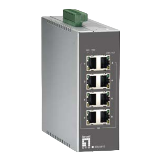
Page 6: Front Panel Display
Eight 10/100Base-TX ports Eight 10/100Base-TX ports + one 100Base-FX port Six 10/100Base-TX ports + two 100Base-FX ports Four 10/100Base-TX ports + four 100Base-FX ports Connectivity RJ-45 connector SC or ST connector on 100Base-FX fiber port IES-0810 User Manual Page 6... -
Page 7: Installation
· Surrounding electrical devices should not exceed the electromagnetic field (RFC) standards. · Make sure that the switch receives adequate ventilation. Do not block the ventilation holes on each side of the switch · The power outlet should be within 1.8 meters of the switch. IES-0810 User Manual Page 7... -
Page 8: Din Rail Mounting
Installation: Place the switch on the DIN rail from above using the slot. Push the front of the switch toward the mounting surface until it audibly snaps into place. Removal: Pull out the lower edge and then remove the switch from the DIN rail. IES-0810 User Manual Page 8... -
Page 9: Connecting To Power
Step 1: Connect the supplied AC to DC power adapter to the receptacle on the topside of the switch. Step 2: Connect the power cord to the AC to DC power adapter and attach the plug into a standard AC outlet with the appropriate AC voltage. IES-0810 User Manual Page 9... -
Page 10: Alarms For Power Failure
Special note: The relay output is normal open position when there is no power to the switch. Please do not connect any power source to this terminal to prevent the shortage to your power supply. IES-0810 User Manual Page 10... -
Page 11: Connecting To Your Network
Connect one end of the cable to the switch and the other end to a desired device. Step 5: Once the connections between two end devices are made successfully, turn on the power and the switch is operational. IES-0810 User Manual Page 11... -
Page 12: Specifications
EN61000-4-3 (Radiated RFI Standards) EN61000-4-4 (Burst Standards) EN61000-4-5 (Surge Standards) EN61000-4-6 (Induced RFI Standards) EN61000-4-8 (Magnetic Field Standards) EN61000-4-11 (Voltage Dips Standards) Environmental Test IEC60068-2-6 Fc (Vibration Resistance) Compliance IEC60068-2-27 Ea (Shock) IEC60068-2-32 Ed (Free Fall) IES-0810 User Manual Page 12... -
Page 13: Appendix A - Connector Pinouts
Standard Port Uplink Port Output Transmit Data + Input Receive Data + Output Transmit Data - Input Receive Data - Input Receive Data + Output Transmit Data + Input Receive Data - Output Transmit Data - IES-0810 User Manual Page 13...
Need help?
Do you have a question about the IES-0810 and is the answer not in the manual?
Questions and answers