Ferroli Pegasus F2 51 Installation And Maintenance Instructions Manual
Gas-fired cast-iron boilers with electronic ignition and flame rectification monitoring
Hide thumbs
Also See for Pegasus F2 51:

Related Manuals for Ferroli Pegasus F2 51


Summary of Contents for Ferroli Pegasus F2 51
- Page 1 INSTALLATION AND MAINTENANCE INSTRUCTIONS PEGASUS F2 GAS-FIRED CAST-IRON BOILERS WITH ELECTRONIC IGNITION AND FLAME RECTIFICATION MONITORING Models 51 - 68 - 85 - 102...
- Page 2 Pegasus F2...
-
Page 3: Table Of Contents
Contents 1. General technical data 2. Dimensions and technical data 3. Installation 4. Wiring diagrams 5. Startup and shutdown 6. Gas regulation 7. Conversion 8. Maintenance and cleaning 9. Fault finding Pegasus F2... -
Page 4: General Technical Data
1. GENERAL TECHNICAL DATA 1.01 Introduction The Pegasus F2, with CE approval, is designed for use with natural gas (G20) or LPG (G31) for indirect central heating and hot water. 1.02 Installation requirements Only CORGI registered installers should fit the Pegasus boilers. The boiler installation should comply with relevant British Standards Specifications, codes of practice, and Current Building Regulations, together with any special Regional Requirements of the Local Authorities, gas supplier and Insurance Companies. -
Page 5: Technical Data
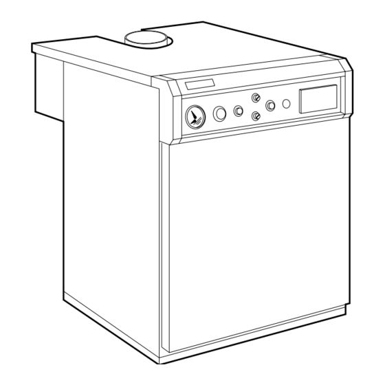
The boiler is designed to operate with a flow temperature of 82°C and a maximum ∆t of 20°C. HEAT HEAT INPUT HEAT INPUT NUMBER OF MODEL OUTPUT (NETT) (GROSS) SECTIONS Pegasus F2 51 62,2 Pegasus F2 68 74,8 Pegasus F2 85 93,5 103,8 Pegasus F2 102 124,3 WEIGHT... - Page 6 2.03 Main components Front view of the boiler without front casing Fig. 2a Control panel Fig. 2b Control panel Temperature-pressure gauge 10. Gas valve Boiler control thermostat 11. Pilot burner assembly Ignition lockout re-set botton 12. Gas burner manifold Boiler on/off switch 13.
- Page 7 ∆P mbar 2.04 Characteristic pressure drop curve Water pressure drop in all models is shown in fig. 3. The following diagram shows the pressure drop in the boiler as a function of the water flow rate. Fig. 3 6 7 8 9 10 Flow rate 2.05 Safe discharge of combustion products...
- Page 8 3. BOILER INSTALLATION (To be performed by qualified personnel only) 3.01 General warnings The boiler should be installed according to current regulations (see para 1.02). We suggest fitting isolating valves between the boiler and the heating system to isolate the boiler from the system if necessary.
- Page 9 4. WIRING AND CONNECTION DIAGRAMS 4.01 Electrical connections - Electrical connections should be performed according to the diagrams shown here. - Connect the boiler to a single-phase, phase neutral, 230 V ~ 50 Hz power supply through a standard terminal block or outlet with 2A max. fuses connected between the boiler and the power support. Remember that the boiler should always be provided with good earthing.
- Page 10 Electrical connections diagram for mod. 51-68 S 4561 B HONEYWELL 5 6 7 1 2 3 230V 50Hz Fig. 5b 24 Spark electrode 98 Boiler on/off switch 25 Pilot burner 114 Water pressure switch (not supplied) 32 Pump (not supplied) 116 Gas pressure switch 49 Limit thermostat (manual reset) 117 Main gas valve...
- Page 11 General wiring diagram for mod. 85-102 230V 50Hz S 4561 B HONEYWELL Fig. 5c 24 Spark electrode 98 Boiler on/off switch 25 Pilot burner 114 Water flow pressure switch (not supplied) 32 Pump (not supplied) 116 Gas pressure switch 49 Limit thermostat (manual reset) 117 Main gas valve 63 Boiler control thermostat 118 Pilot light gas valve...
- Page 12 Electrical connections diagram for mod. 85-102 S 4561 B HONEYWELL 5 6 7 14 16 230V 50Hz Fig. 5d 24 Spark electrode 98 Boiler on/off switch 25 Pilot burner 114 Water pressure switch (not supplied) 32 Pump (not supplied) 116 Gas pressure switch 49 Limit thermostat (manual reset) 117 Main gas valve 63 Boiler control thermostat...
- Page 13 4.02 Access to the control panel internal components For access to the terminal block and the internal components of the control panel, proceed as follows: a - Shut off the power supply to the boiler. b - Lift off the boiler cover (held in place by slot pins). c - Unscrew the two screws that hold the plastic panel against the side of the boiler .
-
Page 14: Startup And Shutdown
5. STARTUP AND SHUTDOWN 5.01 Checks to be carried out at first startup It is good practice to check the following at first startup: that the cutoff valves between the boiler and heating system are open; that all is well pressurized and vented; that there are no gas or water leaks from the water system or boiler;... - Page 15 - Check the efficiency of the flue while the boiler is working. - Check that there are no leaks from the points where the boiler/flue connects to the boiler and the flue. - Check that gas consumption, measured by the gas meter, matches the figure indicated in the technical data table.
- Page 16 6.02 Gas pressure adjustment with the “BM 762-014” valve in models 54 - 68 Adjust the supply pressure at the main burners by turning the stabilizer screw 7 (fig. 7). To increase the pressure, turn the screw clockwise. To decrease the pressure, turn the screw anticlockwise.
- Page 17 6.03 Gas pressure adjustment with the “DUNGS MBDLE 407 BO1” valve in model 85 - 102 Fig. 8 Key: 1. Inlet gas pressure test point (Burner pressure is measured at test point on burner manifold) 2. Pilot burner supply 3. Integral gas pressure switch 4.
- Page 18 Gas pressure adjustment: - Move the protective cover by turning it on its hinges. - Using a small screwdriver (no. 3), turn the regulating screw to set the required pressure. Note: The pilot light requires no adjustments. Fig. 8a Main gas flow rate adjustment (valve V2) - Loosen the securing screw using a screwdriver.
- Page 19 6.04 Pilot burner unit (fig. 9) 3 ÷ 4 mm Combustion chamber cover plate Inspection window Fig. 9 Pilot burner Ignition electrode Flame rectification probe Pilot injector Ht lead Pilot gas supply FUEL CONVERSION (from natural to L.P.G. Gas) 7.01 Replacing the main and pilot burner injectors To replace the main and pilot injectors proceed as follows: - Turn off the gas and switch off the power supply to the boiler.
-
Page 20: Maintenance And Cleaning
8. MAINTENANCE AND CLEANING The following operations are to be performed by qualified personnel only. 8.01 Seasonal inspection of the boiler and flue Before the beginning of winter you should perform a general inspection of the boiler, heating system and flue. The inspection should verify: That the boiler flueways, burner and flue are clean. -
Page 21: Fault Finding
9. FAULT FINDING Fault Cause and Corrective Action The pilot burner is clogged or dirty. After a few startup attempts, the electronic control unit fails to ignite the boiler Check that the gas flow to the boiler is normal and that air in the pipes has been removed. - Page 22 Check that the boiler is perfectly clean. Check that the boiler rating is in proportion to the system. System water temperature is Check the functioning of the regulating thermostat. too high or too low Check the pump is not blocked. Make sure the pump characteristics are in proportion to the size of the system.
- Page 23 Pegasus F2...
- Page 24 ALL SPECIFICATIONS SUBJECT TO CHANGE Stockton Close, Minworth Industrial Park, Minworth, Sutton Coldfield, West Midlands B76 IDH Sales: 0121/3133030 Service: 0121/3131030 Fax 0121/3132319...
Need help?
Do you have a question about the Pegasus F2 51 and is the answer not in the manual?
Questions and answers