Carrier HDB Installation Manual
Room controller 2
Hide thumbs
Also See for HDB:
- Owner's manual (36 pages) ,
- Installation manual (63 pages) ,
- Installation manual (63 pages)
Table of Contents
Advertisement
Available languages
Available languages
Advertisement
Chapters
Table of Contents

Related Manuals for Carrier HDB


Summary of Contents for Carrier HDB
- Page 1 Carrier Room Controller 2 2 WAY InstAllAtIon MAnuAl MontAGE-InstRuCtIEs MAnuAlE DI InstAllAzIonE O K MAnuEl D’InstAllAtIon MAnuAl DE InstAlAção InstAllAtIonsAnWEIsunG InstAllAtIonsMAnuAl MAnuAl DE InstAlACIÓn AsEnnusoHJE...
- Page 2 HDB - Carrier Room Controller 2 EnGlIsH Installation Manual ItAlIAno Manuale di installazione FRAnçAIs Manuel d’installation DEutsCH Installationsanweisung EsPAÑol Manual de instalación nEDERlAnDs Montage-instructies K O K PoRtuGuÊs Manual de instalação sVEnsKA Installationsmanual suoMI Asennusohje...
-
Page 3: Table Of Contents
HDB - Carrier Room Controller 2 Installation manual This control system only operates with all hydronic indoor units. Contents Page Aspect and display ....................General information ....................Choosing the installation site ..................Installation ......................... Electrical connections ....................Room controller 2 configuration ................. -
Page 4: Aspect And Display
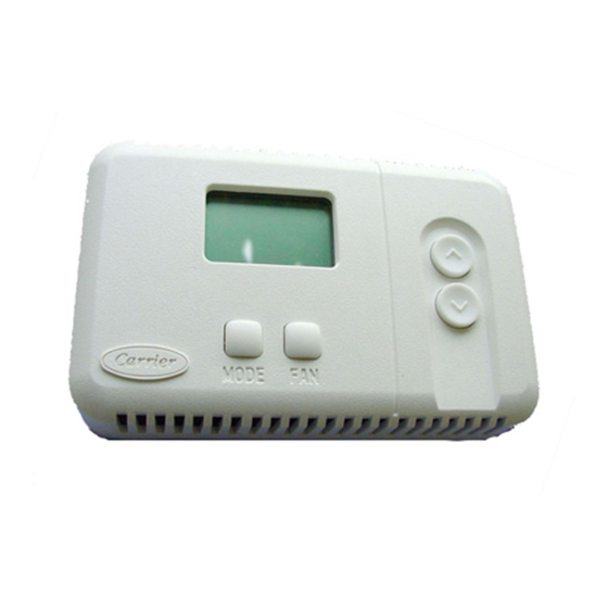
HDB - Carrier Room Controller 2 aspect and display a = Display C = Key for selecting the operating mode D = Key for increasing temperature/changing louver setting E = Button for selecting the fan speed/ louver mode selection F = Key for decreasing temperature/changing louver setting... -
Page 5: General Information
HDB - Carrier Room Controller 2 General information E N G L I S H Power IMPoRTaNT: Read the entire instruction manual before starting the Note that the Room Controller 2 requires no batteries and is not installation. “power stealing”. It requires 12 VDC to be connected for proper operation, which is easily obtained from the Unit connected to it. -
Page 6: Installation
HDB - Carrier Room Controller 2 Installation Mounting • Match and connect equipment wires to proper terminals in the connector block. Both power and communication wires must be connected waRNING: correctly for proper Room Controller operation. Before installing the Room Controller 2, turn off all power to the Unit that will supply power to the Room Controller 2. -
Page 7: Electrical Connections
HDB - Carrier Room Controller 2 Electrical connections and Room Controller 2 configuration E N G L I S H Connection of Room Controller 2 to HDB control panel box waRNING: Before connecting any wiring to the Room Controller 2, turn off all power to the unit that will supply power to the Room Controller, 2. -
Page 8: Room Controller 2 Configuration
HDB - Carrier Room Controller 2 Room Controller 2 configuration, troubleshooting The units are configured at the factory. In the case of check or . Press FAN button to send the unit the new configuration; change, the installer should follow the instructions below: reception of the new vales will be confirmed by the unit. - Page 9 HDB - Carrier Room Controller 2 Manuale di installazione Questo sistema di controllo funziona con tutte le unità interne idroniche. Indice Pagina Aspetto e display ....................... Informazioni generali ....................Scelta del luogo di installazione ................. Installazione ......................Collegamenti elettrici ....................
-
Page 10: Aspetto E Display
HDB - Carrier Room Controller 2 Aspetto e display A = Display C = Selezione della modalità di funzionamento D = Incrementare la temperatura/modifica impostazioni louver e = Selezione velocità ventilatore/selezione modalità louver F = Decrementare la temperatura/ modifica impostazione... -
Page 11: Informazioni Generali
HDB - Carrier Room Controller 2 Informazioni generali I T A L I A N O Alimentazione IMPORTANTe: Leggere attentamente questo manuale prima di iniziare Il Room Controller 2 non necessita di batterie per il funzionamento l’installazione. corretto esso ha bisogno di 12 VDC e cioè facilmente ottenibile da qualsiasi unità... -
Page 12: Installazione
HDB - Carrier Room Controller 2 Installazione Montaggio • Collegare i cavi ai relativi terminali sulla morsettiera. I cavi di alimentazione e quelli di comunicazione devono essere collegati correttamente per un buon funzionamento del ATTeNzIONe: Room Controller 2. Prima di installare il Room Controller 2, togliere l'alimentazione elettrica verso l'unità... -
Page 13: Collegamenti Elettrici
• Per confermare la modifica eseguita su un valore, premere • I valori configurabili sono riportati in tabella. Tutti I valori impostati sempre il pulsante MODE, altrimenti il cambiamento verrà perso. da fabbrica, sono sottolineati all’interno della colonna “Valori”. Tabella di configurazione per le unità HDB Item Valore Descrizione... -
Page 14: Problemi E Soluzioni
HDB - Carrier Room Controller 2 Configurazione Room Controller 2, problemi e soluzioni Le unità vengono pre-configurate in fabbrica. • Premere il pulsante FAN per trasmettere all’unità la nuova Nel caso di verifica o modifica da parte dell’installatore, seguire le configurazione, l’unità... - Page 15 HDB - Carrier Room Controller 2 Manuel d'installation Ce dispositif de contrôle fonctionne uniquement avec toutes les unités intérieures hydrauliques. Table des Matières Page Aspect et affichage ....................Informations générales ..................... Choix du site d’installation ..................Installation ......................... Les branchements électriques ..................
- Page 16 HDB - Carrier Room Controller 2 Aspect et affichage A = Affichage C = Touche pour la sélection de la modalité de fonctionnement D = Augmenter la température / modifier paramétrage louver e = Touche pour la sélection de la vitesse de ventilation / sélection mode ailette (louver)
- Page 17 HDB - Carrier Room Controller 2 Informations générales FRANÇAIS Alimentation électrique IMpoRTANT: Le Room Controller 2 n’a pas besoin de batteries et ne demande lire attentivement ce manuel d’instructions pas un apport d’énergie important. avant de commencer la mise en place de l’appareil.
- Page 18 HDB - Carrier Room Controller 2 Installation Montage • Connecter les câbles avec la borne correspondante sur la barrette de raccordement et les connecter. Il est nécessaire que les câbles d’alimentation et de communication soient AVeRTISSeMeNT: Avant d’installer le Room Controller 2, déconnecter toutes branchés correctement pour que le Room Controller 2...
- Page 19 • Valider le changement de valeur en appuyant sur le bouton Les valeurs programmées à l’usine sont celles soulignées dans MODE, autrement la valeur ne sera pas mémorisée. la colonne « Valeurs ». Tableau de configuration pour les unités HDB Article Valeur Description Chauffage/Rafraîchissement à...
- Page 20 HDB - Carrier Room Controller 2 Configuration du Room Controller 2, dépistage des problèmes de fonctionnement Les unités sont configurées à l’usine. En cas de contrôle ou de • Appuyer sur le bouton FAN pour communiquer à l’unité la changement par l’installateur, suivre les instructions : nouvelle configuration ;...
- Page 21 HDB - Carrier Room Controller 2 Installationshandbuch Diese Kontrolleinheit funktioniert mit allen Hydronischen Innengeräten. Inhalt Seite Aussehen und Display ....................Allgemeine Informationen ..................Wahl des Installationsorts ..................Installation ......................... Elektroanschlüsse ..................... Room Controller 2-Konfiguration ................Störungsermittlung ....................InSTAllATIonSDIAgRAmm Handbuch lesen...
-
Page 22: Aussehen Und Display
HDB - Carrier Room Controller 2 Aussehen und Display A = Display C = Taste zur Wahl der Betriebsweise D = Temperaturerhöhung/Änderung der Einstellung der Luftklappen E = Taste zur Wahl der Belüftungsgeschwindigkeit / Selektion Luftklappen-Modus F = Temperaturreduzierung/ Änderung der Einstellung... -
Page 23: Allgemeine Informationen
HDB - Carrier Room Controller 2 Allgemeine Informationen DEUTSCH Versorgung WICHTIg: lesen Sie dieses Handbuch sorgfältig durch, bevor Sie das Der Room Controller 2 braucht keine Batterie und ist gerät einschalten. energiesparend. Für korrekten Betrieb braucht er 12 VDC Gleichstrom, der leicht vom Gerät geliefert werden kann, an das er angeschlossen ist. -
Page 24: Installation
HDB - Carrier Room Controller 2 Installation montage • Die zusammengehörigen Gerätekabel an die korrekten Klemmen auf dem Klemmblock anschließen. Für korrekten Betrieb des Room Controllers 2 müssen sowohl Versorgungs- ACHTUng: als auch Kommunikationskabel korrekt angeschlossen werden. Vor der Installation des Room Controllers 2 das gerät, das den Room Controller 2 versorgt, ausschalten. -
Page 25: Elektroanschlüsse
HDB - Carrier Room Controller 2 Elektroanschlüsse und Room Controller 2 Konfiguration DEUTSCH Verbindung des Room Controllers 2 an das HDB Schaltbrett WARnUng: Ehe der Room Controller 2 angeschlossen wird, den Strom zu dem gerät, das den Room Controller 2 versorgt, ausschalten. Elektrische Schläge können zu Verletzungen oder sogar zum Tod führen. -
Page 26: Room Controller 2-Konfiguration
HDB - Carrier Room Controller 2 Room Controller 2 Konfiguration, Störungsermittlung Die Geräte werden im Werk konfiguriert. Im Falle von Kontrolle . Die FAN Taste drücken, um die neue Konfiguration auf das Gerät oder Änderung sollte der Installateur die folgenden Anweisungen zu übertragen;... - Page 27 HDB - Carrier Room Controller 2 Manual de instalación Este dispositivo de control funciona con todos las unidades internas hidrónicas. Índice Página Aspecto y display ....................... Informaciones generales ................... Elección del lugar de instalación ................Instalación ......................... Conexiones eléctricas ....................
- Page 28 HDB - Carrier Room Controller 2 Aspecto y display A = Display C = Selección de la modalidad de funcionamiento D = Aumentar la temperatura/modificación configuración louver E = Selección velocidad del ventilador/Selección modalidad louver F = Disminuir la temperatura/modificación configuración louver S = Sensor de temperatura ambiente V = Tornillos de sujeción panel trasero...
- Page 29 HDB - Carrier Room Controller 2 informaciones generales ESPAÑOL Suministro eléctrico iMPORtAntE: Leer atentamente este manual de instruc ciones antes de El Room Controller 2 no precisa baterías y gasta poca energía. iniciar la instalación del aparato. Para funcionar correctamente, se debe alimentar a 12 VDC; esta tensión se puede tomar fácilmente de una de las unidades.
- Page 30 HDB - Carrier Room Controller 2 instalación Montaje • Acoplar los cables con el borne correspondiente del bloque terminal y conectarlo. Para que el Room Controller funcione, es necesario que los cables de suministro y de comunicación ADVERtEnCiA: estén conectados correctamente.
- Page 31 • Para convalidar el cambio realizado de un valor, apretar Todos los valores programados de fábrica aparecen subrayados siempre el pulsador MODE; de lo contrario el cambio se dentro de la columna “Valores”. perderá. tabla de configuración para las unidades HDB item Valor Descripción calentamiento/refrigeración remotos...
- Page 32 HDB - Carrier Room Controller 2 Configuración del Room Controller 2, localización de averías Las unidades son preconfiguradas en fábrica. En caso de • Activar el pulsador FAN para transmitir a la unidad la nueva verificación o modificación por parte del instalador, seguir las configuración, la unidad confirmará...
- Page 33 HDB - Carrier Room Controller 2 Montage-instructies Dit regelsysteem werkt alleen met alle interne hydronische eenheden. Inhoud Blz. Aspect en display ....................Algemene informatie ....................Plaats van opstelling ....................Montage ........................Elektrische aansluitingen ..................Configuratie van de Room Controller 2 ..............
-
Page 34: Aspect En Display
HDB - Carrier Room Controller 2 aspect en display a = Display C = Werkingsmodaliteit D = Toename van de temperatuur/wijziging instellingen louvre e = Keuze ventilatorsnelheid / selectie louvremodus F = Afname van de temperatuur/wijziging instellingen louver s = Sensor ruimteluchttemperatuur V = Fixatieschroeven achterpaneel ... -
Page 35: Algemene Informatie
• Wanneer men zich niet houdt aan de montage-instructies dan vervalt de garantie. • Controleer de zending bij aankomst op transportschade. Meld eventuele zichtbare schade onmiddellijk telefo nisch aan Carrier BV en laat de vervoerder een aante kening maken op de vrachtbrief. Installeer of gebruik geen bescha digde apparatuur. -
Page 36: Montage
HDB - Carrier Room Controller 2 Montage • Sluit de bedrading van de unit aan op de juiste klemmen op Montage de klemmenstrook. Zowel voedings- als communicatiekabels moeten correct worden aangesloten voor een goede werking WaaRsCHUWIng: van de Room Controller 2. - Page 37 HDB - Carrier Room Controller 2 electrische aansluitingen en configuratie van de Room Controller 2 neDeRlanDs aansluiting van de Room Controller 2 op de HDB- schakelkast WaaRsCHUWIng: Voordat u de Room Controller 2 gaat monteren moet de hoofdstroom worden uitgeschakeld. elektrische schokken kunnen persoonlijk letsel en zelfs de dood veroorzaken.
-
Page 38: Elektrische Aansluitingen
HDB - Carrier Room Controller 2 Configuratie van de Room Controller 2, storingzoeken De units zijn in de fabriek geconfigureerd. Bij controles of . Druk op de VENTILATOR-toets om de nieuwe configuratie naar veranderingen moet de installateur de onderstaande instructies de unit te sturen;... - Page 39 HDB - Carrier Room Controller 2 . .................... ..................... ................ ...................... .................. 2 ( 2 ) ..........
- Page 40 HDB - Carrier Room Controller 2 A = C = D = / E = / Επιλογή τρόπου λειτουργίας περσίδας F = / ...
- Page 41 HDB - Carrier Room Controller 2 E : , 2 . . 12 VDC ...
- Page 42 HDB - Carrier Room Controller 2 • . : 6 mm . ( 2, ...
- Page 43 HDB - Carrier Room Controller 2 Room Controller2 E 2 HDB : 2, 2. ...
- Page 44 HDB - Carrier Room Controller 2 Room Controller 2, Οι μονάδες διαμορφώνονται στο εργοστάσιο. Σε • Πατήστε το κουμπί επιλογής τρόπου λειτουργίας για περίπτωση ελέγχου ή αλλαγής, ο εγκαταστάτης πρέπει να να ελέγξετε ή να αλλάξετε την προκαθορισμένη τιμή, ακολουθήσει τις παρακάτω οδηγίες: χρησιμοποιώντας τα πλήκτρα ΠΑΝΩ (UP) και ΚΑΤΩ • Έλεγχος όλων των ηλεκτρικών συνδέσεων (οδηγίες και (DOWN) ηλεκτρικά σχεδιαγράμματα) • Σβήσιμο του χειριστηρίου CRC και ταυτόχρονο πάτημα Σημείωση: Αφού περάσουν 30 δευτερόλεπτα χωρίς των κουμπιών ΠΑΝΩ (UP) και ΚΑΤΩ (DOWN) για να πατήσετε κανένα κουμπί, το σύστημα ελέγχου θα...
- Page 45 HDB - Carrier Room Controller 2 Manual de instalação Este sistema de controlo funciona com todas as unidades internas hidrónicas. Índice Página Aspecto e ecrã ......................2 Informações gerais ....................3 Escolha do lugar da instalação .................. 3 Instalação ......................... 4 Ligações eléctricas ....................
- Page 46 HDB - Carrier Room Controller 2 Aspecto e Ecrã A = Ecrã C = Selecção da modalidade de funcionamento D = Incrementar a temperatura/alteração configuração grelhas de alimentação (louver) E = Selecção da velocidade ventilador / selecção do modo deflector F = Decrementar a temperatura/alteração configuração...
- Page 47 HDB - Carrier Room Controller 2 Informações gerais PORTUGUÊS Alimentação IMPORTANTE: Antes de iniciar a instalação este manual deve ser lido com O Room Controller 2 não necessita de pilhas para o funcionamento atenção. correcto, o mesmo necessita de 12 VDC, e isto é facilmente obtido por qualquer unidade ligada ao mesmo.
- Page 48 HDB - Carrier Room Controller 2 Instalação Instalação • Ligue os fios aos relativos terminais na régua de bornes. Os fios de alimentação e aqueles de comunicação devem ser ligados correctamente para um bom funcionamento do Room ATENÇÃO: Controller 2.
- Page 49 • Para confirmar a alteração executada sobre um valor, res configurados na fábrica, são marcados na coluna “Valores”. carregue sempre o botão MODE, senão a alteração será perdida. Tabela de configuração para as unidades HDB Item Valor Descrição Resfriamento/Aquecimento remoto Somente resfriamento remoto Activação manual Termistor do Ambiente...
- Page 50 HDB - Carrier Room Controller 2 Configuração do Room Controller 2, problemas e soluções As unidades são configuradas na fábrica. No caso de controlo ou . Carregue o botão FAN para enviar a nova configuração à alteração, o instalador deverá seguir as instruções abaixo: unidade;...
- Page 51 HDB - Carrier Room Controller 2 Installationsmanual Detta kontrollsystem fungerar endast med de interna hydroniska enheterna. Innehållsförteckning Sida Utseende och display ......................2 Allmän information ......................... 3 Val av installationsplats ......................3 Installation ..........................4 Elanslutningar ........................5 Konfigurering av Room Controller 2 ..................5/6 Problem och lösningar..
-
Page 52: Utseende Och Display
HDB - Carrier Room Controller 2 Utseende och display A = Display C = Val av funktionssätt D = Höj temperaturen/ändra inställning av ventilationsgaller E = Val av fläkthastighet / val av luftgallerfunktion F = Sänk temperaturen/ändra inställning av ventilationsgaller S = Temperatursensor för omgivning... -
Page 53: Allmän Information
HDB - Carrier Room Controller 2 Allmän information S V E N S K A Strömförsörjning VIKTIGT! Läs denna manual noggrant innan installationen påbörjas. Room Controller 2 drivs inte med batterier utan behöver 12 V DC för att fungera korrekt. Denna strömförsörjning kan enkelt fås från vilken enhet som helst som Room Controller 2 är ansluten till. -
Page 54: Installation
HDB - Carrier Room Controller 2 Installation Montering • Anslut kablarna till respektive kabelfästen på kopplingsplinten. Matnings- och kommunikationskablarna ska anslutas på ett korrekt sätt för att Room Controller 2 ska fungera på ett bra sätt. OBSERVERA! Innan Room Controller 2 installeras ska elmatningen till enhe- ten som strömförsörjer Room Controller 2 kopplas från. -
Page 55: Elanslutningar
HDB - Carrier Room Controller 2 Elanslutningar och konfigurering av Room Controller 2 S V E N S K A Anslutning av Room Controller 2 till elskåp HDB OBSERVERA! Innan någon typ av anslutning görs ska elmatningen till enheten som strömförsörjer Room Controller kopplas från. -
Page 56: Konfigurering Av Room Controller 2
HDB - Carrier Room Controller 2 Konfigurering av Room Controller 2, problem och lösningar Enheterna är konfigurerade på fabriken. I händelse av kontroll eller . Tryck på FAN-knappen för att skicka den nya konfigureringen till ändring ska installatören följa anvisningarna nedan: enheten. - Page 57 HDB - Carrier Room Controller 2 Asennusohje Tämä ohjausjärjestelmä toimii ainoastaan kaikkien sisäyksiköiden kanssa. Sisältö Sivu Ulkomuoto ja näyttö ......................2 Yleistiedot ..........................3 Asennuspaikan valinta ......................3 Asennus..........................4 Sähkökytkennät ........................5 Room Controller 2:n asetukset ................... 5/6 Ongelmat ja ratkaisut..
- Page 58 HDB - Carrier Room Controller 2 Ulkomuoto ja näyttö A = Näyttö C = Toimintatilan valinta D = Lämpötilan lisääminen / säleikön asetusten muuttaminen E = Puhaltimen nopeuden valinta/ säleikön moodin muuttaminen F = Lämpötilan pienentäminen / säleikön asetusten muuttaminen S = Ympäristön lämpötila-anturi...
- Page 59 HDB - Carrier Room Controller 2 Yleistiedot ja asennuspaikan valinta S U O M I Virtalähde TÄRKEÄÄ: Lue tämä opas huolellisesti ennen asennuksen aloittamista. Room Controller 2 ei tarvitse virtalähteeksi akkua. Laite toimii 12 VDC tasavirralla, jonka se saa helposti siihen kytketystä...
- Page 60 HDB - Carrier Room Controller 2 Asennus Asennus • Liitä johdot kytkentäriman vastaaviin liittimiin. Syöttöjohdot ja yhteysjohdot on liitettävä oikein, jotta Room Con- troller 2 toimii hyvin. HUOM: Ennen Room Controller 2:n asentamista on katkaistava virran- syöttö yksikköön, josta Room Controller 2 saa virran.
- Page 61 HDB - Carrier Room Controller 2 Room Controller 2:n sähkökytkennät ja asetukset S U O M I Room Controller 2:n kytkeminen HDB-sähkötauluun HUOM.: Ennen minkään kytkennän tekemistä on katkaistava virran- syöttö yksikköön, josta Room Controller saa virran. Sähköiskut voivat aiheuttaa erittäin vakavan tapaturman.
- Page 62 HDB - Carrier Room Controller 2 Room Controller 2:n asetukset, ongelmat ja ratkaisut Yksiköt konfiguroidaan tehtaalla. Tarkastuksia tai muutoksia yksikköön; yksikkö vahvistaa uusien arvojen vastaanoton. tehtäessä asentajan tulee seurata alla olevia ohjeita: . Paina MODE-painiketta selataksesi kaikki alla olevassa . Tarkista kaikki sähkökytkennät (ohjeet ja kaapelointikaaviot).
- Page 63 L010127H86 - 0308 Via R. sanzio, 9 - 20058 Villasanta (MI) Italy - tel. 039/3636.1 The manufacturer reserves the right to change any product specifications without notice. La cura costante per il miglioramento del prodotto può comportare senza preavviso, cambiamenti o modifiche a quanto descritto. La recherche permanente de perfectionnement du produit peut nécessiter des modifications ou changements, sans préavis.
Need help?
Do you have a question about the HDB and is the answer not in the manual?
Questions and answers