Viking RDSCD230-5B Service Manual
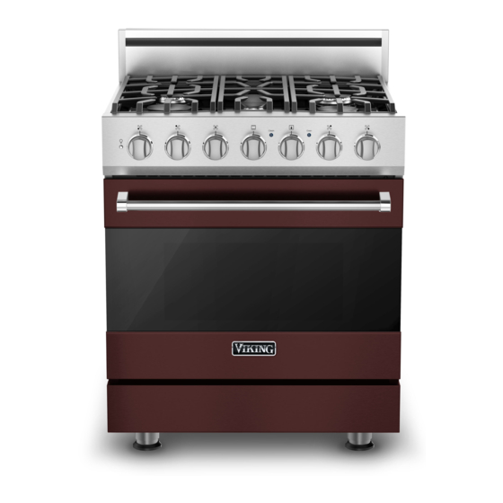
30 inch dual fuel range
Hide thumbs
Also See for RDSCD230-5B:
- Specifications (2 pages) ,
- Manual (36 pages) ,
- Installation manual (14 pages)
Table of Contents
Advertisement
Quick Links
Service
®
Preferred Service
Manual
This manual is to be used by qualified appliance technicians only. Viking
does not assume any responsibility for property damage or personal
injury for improper service procedures done by an unqualified person.
30 Inch Dual
This Base Manual covers general and
specific information including, but not
Fuel Range
limited to the following models:
RDSCD230-5B
SMC-0028
June 2012
Advertisement
Table of Contents
Troubleshooting

Related Manuals for Viking RDSCD230-5B


Summary of Contents for Viking RDSCD230-5B
- Page 1 Service ® Preferred Service Manual This manual is to be used by qualified appliance technicians only. Viking does not assume any responsibility for property damage or personal injury for improper service procedures done by an unqualified person. 30 Inch Dual...
-
Page 2: Table Of Contents
Selector and Thermostat Characteristics ....23 Disassembly ..............24 Access Control Board Assembly ......24 Control and Power Board Removal ....... 24 Motor Capacitor Removal ........25 Door Assembly Removal ........25 Door Gasket Removal ..........25 ©2012 Viking Preferred Service... -
Page 3: Important Information
All safety messages will be preceded by the safety alert symbol and the word “DANGER”, “WARNING”, or “CAUTION”. These words mean: VIKING will not be responsible for any injury or property damage from improper service procedures. If performing service on your own product, you must... -
Page 4: General Information
13. One 12,000 BTU burner 14. One 18,000 BTU burner 15. One 17,000 BTU burner 16. One 8,000 BTU burner 17. Identification plate 18. Three full extension glide racks/Six rack positions 19. Broiler pan (located inside oven) ©2012 Viking Preferred Service... -
Page 5: Warnings
To avoid risk of property damage, personal injury or death; follow information in this manual exactly to prevent a fire or explosion. ©2012 Viking Preferred Service... -
Page 6: Cleaning Safety
BURN OR ELECTRICAL SHOCK HAZARD. Make may be equally harmful. sure all controls are OFF and oven is COOL before cleaning. Failure to do so can result in burns or electrical shock. ©2012 Viking Preferred Service... -
Page 7: Before Using Range
• This appliance is certified by Star-K to meet strict regulations in conjunction with specific instructions self-cleaning cycles, you may sense an odor characteristic of high temperatures. found on www.star-k.org. KEEP THE KITCHEN WELL-VENTED DURING THE SELF-CLEAN CYCLE. ©2012 Viking Preferred Service... -
Page 8: Troubleshooting
Troubleshooting Oven Control Board Connections ©2012 Viking Preferred Service... -
Page 9: Control Board Test Points
P15 brown - grey (Door Open) (**disconnected from board) Oven Door Switch 0 VDC P15 brown - grey (Door Closed) * Resistance checks made with power off. ** Disconnect connector from board for resistance test only. ©2012 Viking Preferred Service... -
Page 10: Control Board Diagnosis
Reconnect power and using your ohmeter to check for continuity between the two relay contacts when the relay is energized. If you read infinite ohms (∞), this indicates a faulty relay and you will need to replace the control board. ©2012 Viking Preferred Service... -
Page 11: Bake Relay (Inner And Outer)
If you read infinite ohms (∞) when the relay is energized, this indicates a faulty relay and you will need to replace the control board. If you read 0 ohms, the relay contact is closing. ©2012 Viking Preferred Service... -
Page 12: Broil Relay (Inner And Outer)
If you read infinite ohms (∞) when the relay is energized, this indicates a faulty relay and you will need to replace the control board. If you read 0 ohms, the relay contact is closing. ©2012 Viking Preferred Service... -
Page 13: Convection Relay
P1 white wire on the power supply board. The resistance should be approximately 18 ohms. If no resistance is read, remove fan to repair/replace (Follow the cooling fan disassembly procedure). ©2012 Viking Preferred Service... -
Page 14: Convection Fan
K6. When it is not energized (as shown above), power flows through the C terminal, to the N.C. (normally closed) contact and out the FWD contact on the board. Counterclockwise (REV)–High Speed To check the individual direction and speeds, perform the following checks: ©2012 Viking Preferred Service... -
Page 15: Testing Control Board
240 VAC and the red LED in front of the relay will be illuminated. If voltage is not present, this indicates a faulty relay and the oven control board will need to be replaced. Also check wiring to the main power supply and repair/ replace as needed. ©2012 Viking Preferred Service... -
Page 16: Door Lock Assembly
If your readings are incorrect or reversed, remove When the door is fully opened, S1 is closed by the motor the latch and inspect, repair/replace (follow latch motor cam. This will signal the board that the door is unlocked. disassembly procedure). ©2012 Viking Preferred Service... -
Page 17: Checking The Door Lock Position Switches
0 ohms. The S2 switch is N.O. and when the door is locked. will read infinite ohms (∞) when the door is unlocked. Shown below is the closed circuit in red. Shown below is the closed circuit in red. ©2012 Viking Preferred Service... -
Page 18: Rtd Sensor
If the RTD resistance is within the specifications given, it is not necessary to replace the RTD. If the RTD test resistance is within specifications and the consumer is having erratic oven temperatures, please call Viking Technical support (1-800-914-4799) for assistance. ©2012 Viking Preferred Service... -
Page 19: Spark Module Test
(If open, replace wire.) replace wire.) 10. If 120 VAC is present in step 5 and the black igniter 11. If 0 ohms present in step 10, replace the spark wire has continuity, replace the spark module. module. ©2012 Viking Preferred Service... -
Page 20: Troubleshooting Guide
Replace thermostat. Open relay K5, K6, K7, K12, K13, Replace oven control board. K14, or K17. Open oven control board. Replace oven control board. Defective oven wiring (shorted, Repair or replace defective wiring. open, or burned). ©2012 Viking Preferred Service... - Page 21 Repair or replace defective wiring. open, or burned). Oven lights inoperable (bulbs OK). Open light switch. Replace light switch. Open oven control board. Replace oven control board. Defective oven wiring (shorted, Repair or replace defective wiring. open, or burned). ©2012 Viking Preferred Service...
-
Page 22: Led Error Codes
Latch 1 flash 1 flash (Oven Probe) Model 2 flashes (The model header failure only occurs at power up of unit. Install correct header and restart power up.) Cooling Fan 3 flashes High limit 4 flashes ©2012 Viking Preferred Service... -
Page 23: Selector And Thermostat Characteristics
9.34 kW 4.63 VDC Resistance checks are made on the thermostat wire harness with the thermostat wire harness disconnected from the board at location P14 and selector disconnected. The harness is connected to P14 for voltage checks. ©2012 Viking Preferred Service... -
Page 24: Disassembly
4. Remove screws and control board from lower mounting plate. Note: During installation, make sure the tabs on the control panel are aligned with the slots on the range. 4. Reverse procedure for installation. 5. Reverse procedure for installation. ©2012 Viking Preferred Service... -
Page 25: Motor Capacitor Removal
2. Remove screws and hinge trim from range. upward. 3. Gently close door until pins stop door. 2. Remove the door gasket from two holes in the bottom of the door liner. 3. Reverse procedure for installation. ©2012 Viking Preferred Service... -
Page 26: Outer Door Panel Assembly Removal
4. Reverse procedure for installation. Note: Use care with insulation, make sure to replace any damaged or missing insulation. Keep vent on inner door panel clear of insulation. 6. Reverse procedure for installation. ©2012 Viking Preferred Service... -
Page 27: Door Hinge Removal
8. Remove bake element from range. to insert a small screwdriver or awl into the connector to guide the wiring and connector thru the oven cavity. 9. Reverse procedure for installation. 4. Reverse procedure for installation. ©2012 Viking Preferred Service... -
Page 28: Rack Support Removal
2. Remove screws that hold the smoke eliminator to the 4. Reverse procedure for installation. top, left, rear corner of the oven liner. 3. Pull down to remove smoke eliminator from oven. 4. Reverse procedure for installation. ©2012 Viking Preferred Service... -
Page 29: Convection Bake Element Removal
Components Accessed). 2. Mark and disconnect all connectors to remove control panel from range. Note: During installation, make sure broil connectors 3. Reverse procedure for installation. go back through the oven liner. 7. Reverse procedure for installation. ©2012 Viking Preferred Service... -
Page 30: Oven Function Selector Removal
Door Switch Removal 1. Access control components (see Control Components Accessed). 2. Remove screws and door switch from range. 3. Mark and disconnect connectors from door switch. 4. Reverse procedure for installation. 4. Reverse procedure for installation. ©2012 Viking Preferred Service... -
Page 31: Oven Light Bulb Removal
Components Accessed). 2. Remove screws and door lock assembly from range. 3. Mark and disconnect connectors from door lock assembly. 4. Remove door lock assembly and door latch insulation from range. 5. Reverse procedure for installation. ©2012 Viking Preferred Service... -
Page 32: Iris Module Removal
5. Remove screw and burner valve from manifold assembly. 6. For the stack burner valve, pull to remove the valve switch from the valve. 3. Reverse procedure for installation. 7. Reverse procedure for installation. 8. Perform gas leak test. ©2012 Viking Preferred Service... -
Page 33: Stack Valve Burner Switch Removal
3. Remove screws and module from range. 6. Lift main top from range. 4. Reverse procedure for installation. Note: Make sure to return insulation to original position under each side trim. 7. Reverse procedure for installation. ©2012 Viking Preferred Service... -
Page 34: Jet Holder Removal
8. Perform gas leak test. 7. Reverse procedure for installation. 8. Perform gas leak test. When removing or installing the gas regulator make sure that you have a wrench on manifold to prevent twisting and damaging the manifold. ©2012 Viking Preferred Service... -
Page 35: Side Trim And Side Panel Removal (Right Side Shown)
7. Remove screws, main top support, and side panel from range. 5. Reverse procedure for installation. Back Panel Removal 1. Remove backguard assembly (see Backguard Assembly Removal). 2. Remove screws and access door from back cover. 8. Reverse procedure for installation. ©2012 Viking Preferred Service... -
Page 36: Cooling Blower Motor Removal
3. Remove four screws and blower mount from range. burner base assembly. 4. Mark and disconnect three connectors and remove 2. Remove orifice from jet holder. blower motor. 3. Reverse procedure for installation. 5. Reverse procedure for installation. ©2012 Viking Preferred Service... -
Page 37: Wiring Diagrams
Wiring Diagrams Wiring Diagram RIBBON CABLE DSCD230 Dual Fuel Range ©2012 Viking Preferred Service...
Need help?
Do you have a question about the RDSCD230-5B and is the answer not in the manual?
Questions and answers