Table of Contents
Advertisement
Quick Links
Download this manual
See also:
Operator's Manual
Advertisement
Table of Contents

Related Manuals for Toro 30069


Summary of Contents for Toro 30069
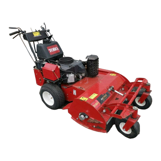
- Page 1 Form No. 3390-262 Rev B Commercial Walk-Behind Traction Unit 18HP Pistol-Grip Hydro Drive Model No. 30069—Serial No. 315000001 and Up *3390-262* B Register at www.Toro.com. Original Instructions (EN)
- Page 2 (Figure safely. which signals a hazard that may cause serious injury or death You may contact Toro directly for product and accessory if you do not follow the recommended precautions. information, help finding a dealer, or to register your product at Toro Commercial Products Service Department Spellbrook, Bishops Stortford, CM23 4BU, England, +44(0)1279 603019, Email: uk.service@toro.com.
-
Page 3: Table Of Contents
Contents Checking the Tire Pressure ........33 Cooling System Maintenance ........33 Cleaning the Air Intake Screen........33 Safety ................4 Brake Maintenance ............34 General Lawn Mower Safety ........4 Servicing the Brake ..........34 Sound Pressure for the 32 RD, 36 RD and 48 Belt Maintenance ............35 RD .............. -
Page 4: Safety
• Before using, always visually inspect to see that guards, Toro designed and tested this mower for reasonably safe and safety devices, such as deflectors are in place and service; however, failure to comply with the following working correctly. -
Page 5: Maintenance And Storage
• To ensure the best performance and safety, – before checking, cleaning or working on the lawn purchase only genuine Toro replacement parts and mower. accessories. Do not use will fit parts and accessories; – after striking a foreign object, inspect the lawn mower they may cause a safety hazard. -
Page 6: Sound Pressure For The 32 Rd, 36 Rd And 48 Rd
Sound Pressure for the 32 RD, Vibration Level for the 48 RD 36 RD and 48 RD Hand-Arm The 32 RD has a sound pressure level at the operator’s ear of Measured vibration level for right hand = 2.5 m/s 87 dBA, which includes an Uncertainty Value (K) of 2 dBA. -
Page 7: Slope Indicator
Slope Indicator G011841 Figure 4 This page may be copied for personal use. 1. The maximum slope you can safely operate the machine on is 20 degrees. Use the slope chart to determine the degree of slope of hills before operating. Do not operate this machine on a slope greater than 20 degrees. Fold along the appropriate line to match the recommended slope. -
Page 8: Safety And Instructional Decals
Safety and Instructional Decals Safety decals and instructions are easily visible to the operator and are located near any area of potential danger. Keep safety signs clear and visible, replace any decal that is damaged or lost. 320006 1. Height of cut 106-2733 40-13–010 1. - Page 9 115-1039 115-4212 1. Parking 2. Parking brake—engaged 1. Hydraulic oil level 3. Warning—do not touch the brake—disengaged hot surface. 2. Read the Operator's Manual. 119-6672 1. Forward 10. Warning—read the Operator's Manual. 2. Neutral 11. Warning—do not operate this machine unless you are trained. 3.
-
Page 10: Setup
Setup Loose Parts Use the chart below to verify that all parts have been shipped. Procedure Description Qty. – No parts required Check the fluids and tire pressure. Operator's Manual Read the Operator's Manual and watch Engine operator's manual the operator training material before Operator training material operating the machine. -
Page 11: Product Overview
Product Overview G016076 Figure 5 G016079 1. Mower deck 4. Controls 2. Brake 5. Handle Figure 6 3. Gas tank 6. Caster wheel 1. Throttle control 6. Operator Presence Control levers (OPC) 7. Handle 2. Speed control lever Controls 3. Ignition switch 8. -
Page 12: Specifications
• Store gasoline in an approved container and A selection of Toro approved attachments and accessories are available for use with the machine to enhance and expand keep it out of the reach of children. Never buy its capabilities. -
Page 13: Think Safety First
of varnish deposits in the fuel system, use fuel stabilizer DANGER at all times. In certain conditions during fueling, static electricity can be released causing a spark which Filling the Fuel Tank can ignite the gasoline vapors. A fire or explosion 1. -
Page 14: Starting And Stopping The Engine
Setting the Parking Brake Stopping the Engine Pull the parking brake lever rearward (Figure Important: In an emergency, you can stop the engine immediately by turning the ignition key to the off position. 1. Move the drive levers to neutral and set the neutral locks. -
Page 15: Operating The Blade Control Knob (Pto)
Engaging the Mower Blades (PTO) 2. Place thumbs on the upper part of the locks and move them back until the pins are in the neutral position 1. To engage blades, squeeze the Operator Presence (Figure 10). Control (OPC) levers against handle grips (Figure 12). -
Page 16: Driving The Machine Forward And Backward
Understanding the Safety Interlock Driving the Machine Forward System and Backward The safety interlock system is designed to prevent the mower The throttle control regulates the engine speed as measured from starting unless: in RPM (revolutions per minute). Place the throttle control in •... -
Page 17: Stopping The Machine
Stopping the Machine 1. To stop the machine, squeeze the drive levers to neutral position and engage neutral locks. 2. Move speed control lever into neutral. 3. Stop the engine; refer to Stopping the Engine. 4. Wait for all moving parts to stop before leaving the operating position. -
Page 18: Adjusting The Caster Position
Figure 16 1. Top axle bolt 2. Lower axle bolt 7. Raise or lower the mounting bracket, so that you can install the 2 axle adjustment bolts in the desired hole location (Figure 16). A tapered punch can be used to help align the holes. -
Page 19: Adjusting The Handle Height
Adjusting the Handle Height The handle position can be adjusted to match the operator's height preference. 1. Remove the hairpin cotter pins and clevis pins from the drive levers and neutral locks (Figure 18). Figure 19 1. Control rod fitting 6. -
Page 20: Height Of Cut Chart
Height of Cut Chart Number of spacers Number of 6 mm (1/4 inch) blade spacers below spindle below caster 13mm (1/2 5mm (3/16 Axle inch) inch) Position 32 mm 38 mm 45 mm 26 mm (1 51 mm (2 (1–1/4 (1–1/2 (1–3/4 inch) - Page 21 79 mm 86 mm 92 mm 98 mm 105 mm (3–1/8 (3–3/8 (3–5/8 inch (3–7/8 (4–1/8 inch) inch) inch) inch) 83 mm 89 mm 95 mm 108 mm 102 mm (4 (3–1/4 (3–1/2 (3–3/4 (4–1/4 inch) inch) inch) inch) inch)
-
Page 22: Maintenance
Maintenance Note: Determine the left and right sides of the machine from the normal operating position. Recommended Maintenance Schedule(s) Maintenance Service Maintenance Procedure Interval • Check the mower belt tension. • Check the hydraulic fluid level. After the first 8 hours •... -
Page 23: Lubrication
Lubrication Figure 20 for locating the grease points on the machine. Grease with No. 2 general-purpose, lithium-based or molybdenum-based grease. 1. Disengage the PTO and set the parking brake. 2. Stop the engine, remove the key, and wait for all moving parts to stop before leaving the operating position. -
Page 24: Engine Maintenance
Engine Maintenance Cleaning the Foam Air Cleaner Element 1. Wash the foam element in liquid soap and warm water. When the element is clean, rinse it thoroughly. Servicing the Air Cleaner 2. Dry the element by squeezing it in a clean cloth. Important: Replace the foam element if it is torn Service Interval/Specification or worn. -
Page 25: Servicing The Engine Oil
Servicing the Engine Oil Checking the Engine-Oil Level 1. Park the machine on a level surface. 2. Disengage the PTO and set the parking brake. 3. Stop the engine, remove the key, and wait for all moving parts to stop before leaving the operating position. 4. -
Page 26: Servicing The Spark Plugs
Changing the Oil Filter 3. Disconnect the wires from the spark plugs (Figure 25). Note: Change the oil filter more frequently when the operating conditions are extremely dusty or sandy. 1. Drain the oil from the engine; refer to Changing the Engine Oil. -
Page 27: Fuel System Maintenance
Installing the Spark Plugs Fuel System 1. Install the spark plugs and the metal washer. Ensure Maintenance that the air gap is set correctly. 2. Tighten the spark plugs to 16 ft-lb (22 N-m). Servicing the Fuel Tank 3. Connect the wires to the spark plugs (Figure 26). -
Page 28: Servicing The Fuel Filter
Servicing the Fuel Filter Drive System Maintenance Replacing the Fuel Filter Perform the following linkage adjustments when the machine Service Interval: Every 200 hours/Yearly (whichever comes needs maintenance. Perform steps Adjust the Speed Control first) Linkage through Adjusting the Tracking. If any adjustment is needed , do them in the order that they are listed. -
Page 29: Adjusting The Neutral Control Linkages
4. Disengage the parking brake. 5. Start the engine and move the throttle ahead to the full throttle position. 6. Place the neutral locks in the full forward position and move the speed control lever to the medium speed position. 7. -
Page 30: Adjusting The Hydro Control Linkages
6. Place the left drive lever in the full forward position. 7. Place the speed control lever in the neutral position. WARNING Electrical system will not perform proper safety shut off with Operator Presence Control (OPC) levers held in place. •... -
Page 31: Adjusting The Control Rod
13. Hold the OPC levers down. 3. Adjust the right side linkage by turning the quick track knob counterclockwise until the tire begins to rotate Note: Hold the OPC levers down whenever the speed forward (Figure 35). control lever is out of the neutral position or the engine 4. -
Page 32: Adjusting The Tracking
Adjusting the Control Rod 1. Adjust the rod length by releasing the drive lever and removing the hairpin cotter pin and clevis pin. Rotate the rod in the rod fitting (Figure 36). 2. Lengthen the control rod if the tire is turning in reverse and shorten the rod if the tire is turning forward. -
Page 33: Checking The Tire Pressure
Cooling System 3. For a heavier drive setting, relocate the spring anchor links to either the medium or heavy duty positions Maintenance (Figure 39). The spring anchor links are attached to the upper rear corner of the hydro drive shields on the left and right sides of the machine. -
Page 34: Brake Maintenance
Brake Maintenance Note: With the parking brake in the released position, the clearance between the tire and the flat bar is approximately 6 mm (1/4 inch) (Figure 41). Servicing the Brake 5. Secure the lower link to the lower brake lever with the hair pin cotter and the clevis pin (Figure 41). -
Page 35: Belt Maintenance
Belt Maintenance Adjusting the Mower Belt Tension Checking the Belts Adjusting the Tension Service Interval: Every 50 hours/Monthly (whichever Service Interval: After the first 8 hours comes first) After the first 25 hours Check the belts for squealing when the belt is rotating, blades slipping when cutting grass, frayed belt edges, burn marks and Every 50 hours cracks are signs of a worn mower belt. - Page 36 Adjusting the PTO Engagement 6. If there is no adjustment left in the turnbuckle and the belt is still loose, position the rear idler pulley in the Linkage middle or front hole (Figure 44). Use the hole that will The PTO engagement linkage adjustment is located beneath give the correct adjustment.
- Page 37 Figure 47 Figure 48 1. Assist arm 5. Assist arm link 2. Front assist arm stop 6. Yoke 1. Bellcrank 3. Switch mounting bracket 3. Rear assist arm stop 7. Hairpin cotter pin 2. Bolts and nuts 4. Switch body 4.
-
Page 38: Hydraulic System Maintenance
Hydraulic System 8. Recheck the fluid level while the fluid is warm. If required, add fluid to the reservoir until it reaches the Maintenance hot level of the baffle. Note: When the fluid is warm, the fluid level is at the top of the hot level of the baffle (Figure 49). -
Page 39: Bleeding The Hydraulic System
2. Stop the engine and wait for all moving parts to stop before leaving the operating position. 3. Raise the rear of the machine up onto jack stands high enough to raise the drive wheels off the ground. 4. Check the hydraulic fluid level. 5. -
Page 40: Mower Deck Maintenance
Checking the Hydraulic Lines Mower Deck Service Interval: Every 100 hours Maintenance Check the hydraulic lines and hoses for leaks, loose fittings, kinked lines, loose mounting supports, wear, weather and Servicing the Cutting Blades chemical deterioration. Make necessary repairs before operating. -
Page 41: Removing The Blades
53). out of balance or bent. To ensure optimum performance and continued safety conformance of the machine, use genuine Toro replacement blades. Replacement blades made by other manufacturers may result in non-conformance with safety standards. 1. Hold the blade bolt with a wrench. -
Page 42: Adjusting The Blade Brake
Sharpening the Blades 5. Engage the blades. Ensure the blade brake pad no longer contacts the pulley groove. 1. Use a file to sharpen the cutting edge at both ends of the blade (Figure 56). Maintain the original angle. The blade retains its balance if the same amount of material is removed from both cutting edges. -
Page 43: Storage
Storage 1. Disengage the power take off (PTO), set the parking brake, and turn the ignition key to off. Remove the key. 2. Remove grass clippings, dirt, and grime from the external parts of the entire machine, especially the engine. Clean dirt and chaff from the outside of the engine's cylinder head fins and blower housing. -
Page 44: Troubleshooting
Troubleshooting Problem Possible Cause Corrective Action The engine will not start, starts hard, or 1. The fuel tank is empty. 1. Fill the fuel tank with gasoline. fails to keep running. 2. The fuel shutoff valve is closed. 2. Open the fuel shutoff valve. 3. - Page 45 Problem Possible Cause Corrective Action The blades do not rotate. 1. The mower deck belt is worn or loose. 1. Check the belt tension. 2. The mower deck belt is broken. 2. Install a new deck belt. 3. The mower deck belt is off a pulley. 3.
-
Page 46: Schematics
Schematics G0161 Electrical Schematic (Rev. A) Hydraulic Schematic (Rev. A) - Page 47 The Way Toro Uses Information Toro may use your personal information to process warranty claims, to contact you in the event of a product recall and for any other purpose which we tell you about. Toro may share your information with Toro's affiliates, dealers or other business partners in connection with any of these activities. We will not sell your personal information to any other company.
- Page 48 Instructions for Obtaining Warranty Service The Toro Company and its affiliate, Toro Warranty Company, pursuant to an If you think that your Toro Product contains a defect in materials or agreement between them, jointly promise to the original purchaser to repair workmanship, follow this procedure: the Toro Products listed below if defective in materials or workmanship.
Need help?
Do you have a question about the 30069 and is the answer not in the manual?
Questions and answers