Table of Contents

Related Manuals for Toro Master Commercial 3000 Series


Summary of Contents for Toro Master Commercial 3000 Series
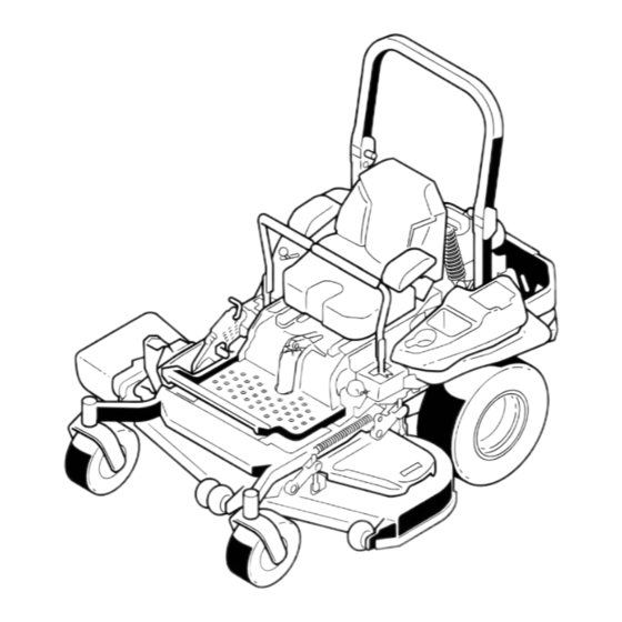
- Page 1 Form No. 3400-682 Rev C Z Master ® Commercial 3000 Series Riding Mower with 52in TURBO FORCE ® Side Discharge Mower Model No. 74994—Serial No. 316000001 and Up *3400-682* C Register at www.Toro.com. Original Instructions (EN)
- Page 2 Authorized Service arrester, as defined in Section 4442, maintained in Dealer or Toro Customer Service and have the model effective working order or the engine is constructed, and serial numbers of your product ready.
-
Page 3: Table Of Contents
Checking the Seat Belt ........51 Safety ............... 4 Checking the Rollover-Protection-System Safe Operating Practices........4 (ROPS) Knobs ..........51 Toro Mower Safety..........6 Adjusting the Tracking ........52 Slope Indicator ........... 7 Checking the Tire Pressure....... 52 Safety and Instructional Decals ......8 Checking the Wheel Lug Nuts...... -
Page 4: Safety
Preparation Safety • Evaluate the terrain to determine what accessories and attachments are needed to properly and Improper use or maintenance can result in injury. safely perform the job. Only use accessories and To reduce the potential for injury, comply with these attachments approved by the manufacturer. - Page 5 Maintenance and Storage Make the necessary repairs before resuming operation. • Disengage drives, set the parking brake, shut off • Keep your hands and feet away from the cutting the engine, and remove the key or disconnect unit. spark-plug wire. Wait for all movement to stop before adjusting, cleaning, or repairing the •...
-
Page 6: Toro Mower Safety
Do not store the machine or a fuel container inside The following list contains safety information specific where there is an open flame, such as near a to Toro products and other safety information that you water heater or furnace. must know. -
Page 7: Slope Indicator
Slope Indicator g011841 Figure 3 This page may be copied for personal use. 1. The maximum slope you can safely operate the machine on is 15 degrees. Use the slope chart to determine the degree of slope of hills before operating. Do not operate this machine on a slope greater than 15 degrees. Fold along the appropriate line to match the recommended slope. -
Page 8: Safety And Instructional Decals
Safety and Instructional Decals Safety decals and instructions are easily visible to the operator and are located near any area of potential danger. Replace any decal that is damaged or lost. decal58-6520 58-6520 decal106-2655 1. Grease 106-2655 1. Warning-do not touch or approach moving belts; remove the ignition key and read the instructions before servicing or performing maintenance. - Page 9 decal110-2068 110-2068 1. Read the Operator's Manual. decal112-9028 112-9028 1. Warning—stay away from moving parts; keep all guards in place. decal107-3069 107-3069 1. Warning–there is no rollover protection when the roll bar is down. decal114-4466 2. To avoid injury or death from a rollover accident, keep the 114-4466 roll bar in the raised and locked position and wear the seat belt.
- Page 10 decal115-9625 115-9625 decal117-3848 1. Parking 2. Parking brake—engaged 117-3848 brake—disengaged 1. Thrown object hazard—keep bystanders a safe distance from the machine 2. Thrown object hazard, mower-do not operate the machine without the deflector, discharge cover, or grass collection system in place. 3.
- Page 11 decal126-4398 126-4398 1. Read the Operator’s 3. Unlock Manual 2. Lock decal121-7551 121-7551 1. Power takeoff (PTO) 4. Continuous variable setting 2. Choke 5. Slow 3. Fast decal127-0326 127-0326 1. Read the Operator's 3. Remove the key from Manual. the ignition and read the Operator's Manual before decal126-2055 performing maintenance...
- Page 12 decalbatterysymbols Battery Symbols Some or all of these symbols are on your battery. 1. Explosion hazard 6. Keep bystanders a safe distance from the battery. 2. No fire, open flame, or 7. Wear eye protection; smoking explosive gases can cause blindness and other injuries.
- Page 13 decal125-9383 125–9383 1. Check hydraulic fluid every 50 operating hours. 3. Check the tire pressure every 50 operating hours. 2. Read the Operator’s Manual for information on lubricating 4. Read the Operator’s Manual before servicing or performing the machine. maintenance.
- Page 14 decal132-0871 132-0871 Note: This machine complies with the industry standard stability test in the static lateral and longitudinal tests with the maximum recommended slope indicated on the decal. Review the instructions for operating the machine on slopes in the Operator’s Manual as well as the conditions in which you would operate the machine to determine whether you can operate the machine in those conditions on that day and at that site.
-
Page 15: Product Overview
Hour Meter Product Overview The hour meter records the number of hours the engine has operated. It operates when the engine is running. Use these times for scheduling regular maintenance (Figure g029631 g008950 Figure 4 Figure 6 8. Rear-shock assembly 1. -
Page 16: Specifications
A selection of Toro approved attachments and accessories is available for use with the machine to enhance and expand its capabilities. Contact your Authorized Service Dealer or Distributor or go to www.Toro.com for a list of all approved attachments and accessories. -
Page 17: Operation
Operation DANGER In certain conditions during fueling, static Note: Determine the left and right sides of the electricity can be released, causing a spark machine from the normal operating position. that can ignite the gasoline vapors. A fire or explosion from gasoline can burn you and Adding Fuel others and can damage property. -
Page 18: Checking The Engine-Oil Level
chance of varnish deposits in the fuel system, use fuel stabilizer at all times. Filling the Fuel Tank Note: Do not fill the fuel tank completely full. Fill the fuel tank to the bottom of the filler neck. The empty space in the tank allows the gasoline to expand. -
Page 19: Using The Rollover-Protection System
40 to 50 hours of break-in time for new machines to develop full power and best performance. Using the Rollover-Protection System (ROPS) WARNING To avoid injury or death from rollover: keep the roll bar in the fully raised, locked position and use the seat belt. -
Page 20: Entering The User Position
Entering the User Position Use the mower deck as a step to get into the user position (Figure g000963 Figure 10 1. Safe Zone—use the 3. Water machine here on slopes less than 15 degrees or g029797 Figure 9 flat areas. 2. -
Page 21: Operating The Parking Brake
Operating the Parking Operating the Mower Brake Blade-Control Switch (PTO) Always set the parking brake when you stop the The blade-control switch (PTO) starts and stops the machine or leave it unattended. mower blades and any powered attachments. Setting the Parking Brake Engaging the Blade-Control Switch (PTO) WARNING... -
Page 22: Operating The Ignition Switch
Operating the Ignition Switch Turn the ignition key to the S position TART (Figure 17). Note: When the engine starts, release the key. Important: Do not engage the starter for g008946 Figure 16 more than 5 seconds at a time. If the engine fails to start, wait 15 seconds between attempts. -
Page 23: Using The Fuel-Shutoff Valve
Using the Fuel-Shutoff Valve The fuel-shutoff valve is located under the seat. Move the seat forward to access it. Close the fuel-shutoff valve for transport, maintenance, and storage. Ensure that the fuel-shutoff valve is open when starting the engine. g008948 Figure 18 1. -
Page 24: Starting And Shutting Off The Engine
Starting and Shutting Off first time after the fuel system has been without fuel completely. the Engine Starting the Engine Raise the ROPS up, lock it into place, sit on the seat, and fasten the seat belt. Move the motion-control levers to the position. -
Page 25: Using The Safety-Interlock System
Understanding the Safety-Interlock System The safety-interlock system is designed to prevent the engine from starting unless: • The parking brake is engaged. • The blade-control switch (PTO) is disengaged. • The motion-control levers are in the N EUTRAL LOCK position. The safety-interlock system also is designed to shut off the engine when you move the traction controls from the locked position with the parking brake engaged or... -
Page 26: Driving Forward Or Backward
Testing the Safety-Interlock CAUTION System Machine can spin very rapidly. You may lose control of machine and injure yourself or Service Interval: Before each use or daily damage the machine. Test the safety-interlock system before you use the • Use caution when making turns. machine each time. -
Page 27: Shutting Off The Machine
Driving Forward Driving Backward Move the levers to the center, unlocked position. Note: The engine shuts off if you move the traction-control levers with the parking brake engaged. To go backward, slowly pull the motion-control levers rearward (Figure 25). To stop, pull the motion-control levers to the N EUTRAL position. - Page 28 an U position for the transport position of the NLOCK mower deck (Figure 26).
- Page 29 Adjusting the Height-of-Cut Pin The height-of-cut is adjusted from 25 to 140 mm (1 to 5-1/2 inches) in 6 mm (1/4 inch) increments by relocating the clevis pin into different hole locations. Move the transport lock to the L position. Push on the deck-lift pedal with your foot and raise the mower deck to the transport position (also the 140 mm (5-1/2 inch) cutting-height...
-
Page 30: Adjusting The Anti-Scalp Rollers
Adjusting the Anti-Scalp Rollers Whenever you change the height-of-cut, adjust the height of the anti-scalp rollers. Disengage the blade-control switch (PTO), move the motion-control levers to the N EUTRAL LOCK position, and set the parking brake. Shut off the engine, remove the key, and wait for all moving parts to stop before leaving the operating position. -
Page 31: Adjusting The Flow-Baffle-Cam Locks
Adjusting the Flow-Baffle-Cam Locks You can adjust the mower-discharge flow for different types of mowing conditions. Position the cam locks and baffle to achieve the best quality of cut. Note: Certain models have nuts and bolts in place of the flow baffle locks. Disengage the blade-control switch (PTO), move the motion-control levers to the N EUTRAL... -
Page 32: Positioning The Flow Baffle
Positioning the Flow Baffle Position C This is the fully open position. Use this position for The following figures are only recommendations the following: for use. Adjustments vary by grass type, moisture content, and height of grass. • Tall, dense grass mowing conditions. Note: If the engine power draws down and the •... -
Page 33: Unlatching The Seat
Unlatching the Seat Adjusting the MyRide™ Suspension System The MyRide™ suspension system adjusts to provide a smooth and comfortable ride. Adjusting the rear 2-shock assemblies is the easiest and quickest adjustment for changing the suspension system. Position the suspension system where you are most comfortable. -
Page 34: Using The Drive-Wheel Release Valves
The front-shock assembly is set at the middle position and is normally not adjusted. To adjust the front-shock assembly, open the floor pan and adjust it by using a spanner wrench (Toro Part No. 132-5069) or a slip-joint pliers (Figure 38). -
Page 35: Using The Side Discharge
Note: Make sure that the release valves are in the DANGER fully horizontal position when operating the machine, Without a grass deflector, discharge cover, or or severe damage to the hydraulic system could occur. complete grass catcher assembly mounted in Disengage the blade-control switch (PTO) and place, you and others are exposed to blade turn the ignition key to off. -
Page 36: Transporting The Machine
Transporting the Machine Back the machine up the ramp and drive it forward down the ramp (Figure 41). Use a heavy-duty trailer or truck to transport the machine. Ensure that the trailer or truck has all necessary brakes, lighting, and marking as required by law. - Page 37 WARNING Loading a machine onto a trailer or truck increases the possibility of a tip-over and could cause serious injury or death. • Use extreme caution when operating a machine on a ramp. • Ensure that the ROPS is in the up position and use the seat belt when loading or unloading the machine.
-
Page 38: Operating Tips
Alternate the mowing direction to keep the grass as necessary. If a blade is damaged or worn, replace standing straight. This also helps disperse clippings, it immediately with a genuine Toro replacement blade. which enhances decomposition and fertilization. Mowing at Correct Intervals Normally, mow every 4 days. -
Page 39: Maintenance
• Adjust the caster-pivot bearing. Every 500 hours • Check the parking-brake adjustment. • Change the hydraulic filters and hydraulic fluid when using Toro® HYPR-OIL™ 500 hydraulic fluid (more often in dirty or dusty conditions). • Replace the inner air filter. -
Page 40: Lubrication
CAUTION If you leave the key in the ignition switch, someone could accidently start the engine and seriously injure you or other bystanders. Remove the key from the ignition before you do any maintenance. Lubrication Greasing the Mower Grease more frequently when operating conditions Service Interval: Every 50 hours—Grease the mower are extremely dusty or sandy. -
Page 41: Lubricating The Caster-Wheel Hubs
Lubricating the Caster-Wheel Hubs Service Interval: Yearly Shut off the engine, wait for all moving parts to stop, and remove the key. Engage the parking brake. g009030 Figure 45 g006115 Figure 47 Remove the dust cap and adjust the caster pivots. -
Page 42: Engine Maintenance
Engine Maintenance With the open end of the wheel facing up, fill the area inside the wheel around the axle full of general-purpose grease. Servicing the Air Cleaner Insert the second bearing and new seal into the wheel. Service Interval: Every 150 hours—Inspect the Apply a thread locking adhesive to the second primary filter and the air-inlet spacer nut and thread it onto the axle with the... -
Page 43: Servicing The Engine Oil
Servicing the Safety Filter Gently slide the primary filter out of the air-cleaner body (Figure 49). Replace the safety filter, never clean it. Note: Avoid knocking the filter into the side of Important: Never attempt to clean the safety the body. filter. - Page 44 Checking the Engine-Oil Level Service Interval: Before each use or daily Note: Check the oil when the engine is cold. WARNING g029644 Contact with hot surfaces may cause personal injury. Keep hands, feet, face, clothing, and other body parts away from the muffler and other hot surfaces.
- Page 45 Changing the Engine Oil Slowly pour approximately 80% of the specified oil into the filler tube and slowly add the Service Interval: After the first 8 hours additional oil to bring it to the Full mark (Figure Every 100 hours (more often in dirty or dusty 53).
-
Page 46: Servicing The Spark Plug
Changing the Engine-Oil Filter Servicing the Spark Plug Service Interval: Every 200 hours Service Interval: Every 200 hours—Check, clean and regap the spark plug. Note: Change the engine-oil filter more frequently when operating conditions are extremely dusty or Make sure that the air gap between the center and sandy. - Page 47 Checking the Spark Plug Important: Replace the spark plug(s) when it has: a black coating, worn electrodes, an oily film, cracks or reuse is questionable. If you see light brown or gray on the insulator, the engine is operating properly. A black coating on the g029645 insulator usually means the air cleaner is dirty.
-
Page 48: Checking The Spark Arrester (If Equipped)
Installing the Spark Plug Fuel System Tighten the spark plug(s) to 24.4 to 29.8 N∙m (18 to Maintenance 22 ft-lb). Replacing the Fuel Filter Service Interval: Every 200 hours The fuel filter is located near the engine on the front or rear side of the engine. -
Page 49: Servicing The Fuel Tank
Electrical System installed at the factory to keep the fuel line away from components that can cause fuel line damage. Maintenance Servicing the Fuel Tank Servicing the Battery Do not attempt to drain the fuel tank. Ensure that an Authorized Service Dealer drains the fuel tank and Service Interval: Monthly services any components of the fuel system. -
Page 50: Servicing The Fuses
important to prevent battery damage when the temperature is below 0°C (32°F). Charge battery for 10 to 15 minutes at 25 to 30 amps or 30 minutes at 10 A. When the battery is fully charged, unplug the charger from the electrical outlet, then disconnect the charger leads from the battery posts (Figure... -
Page 51: Drive System Maintenance
Drive System Maintenance Checking the Seat Belt Service Interval: Before each use or daily Inspect the seat belt for wear, cuts, and proper operation of the retractor and buckle. Replace the seat belt if it is damaged. Checking the Rollover-Protection-System g008966 Figure 63 (ROPS) Knobs... -
Page 52: Adjusting The Tracking
If the machine tracks to the left, loosen the bolts and adjust the right stop plate rearward on the right T-slot until the machine tracks straight (Figure 65). Tighten the stop plate (Figure 65). g029647 Figure 65 Left control lever shown 1. -
Page 53: Checking The Wheel Lug Nuts
Checking the Wheel Lug Important: Make sure that the spring washers are installed correctly as shown in Nuts Figure Install the dust cap (Figure 68). Check and torque the wheel lug nuts to 122 to 129 N∙m (90 to 95 ft-lb). Checking the Wheel Hub Slotted Nut Service Interval: After the first 100 hours... - Page 54 Removing the Clutch Shim Using needle-nose pliers, or by hand, remove the shim. Shut off the engine, wait for all moving parts to stop, and remove the key. Note: Do not discard the shim until you confirm that the clutch functions properly. Engage the parking brake and wait for machine to cool completely.
-
Page 55: Cooling System Maintenance
Cooling System Maintenance Cleaning the Engine Screen and Engine-Oil Cooler Service Interval: Before each use or daily g010873 Figure 74 Remove any buildup of grass, dirt, or other debris from the oil cooler (Figure 75). This helps ensure 1. Feeler gauge adequate cooling, correct engine speed, and reduces the possibility of overheating and mechanical damage to the engine. -
Page 56: Cleaning The Hydraulic Units
Cleaning the Hydraulic Units Service Interval: Before each use or daily Disengage the blade-control switch (PTO) and set the parking brake. Shut off the engine, remove the key, and wait for all moving parts to stop before leaving the operating position. Move the seat forward. -
Page 57: Brake Maintenance
Brake Maintenance Adjusting the Parking Brake Service Interval: After the first 100 hours Every 500 hours thereafter Drive the machine onto a level surface. Disengage the blade-control switch (PTO), move the motion-control levers to the N EUTRAL LOCK position, and engage the parking brake. Shut off the engine, wait for all moving parts to g026961 Figure 78... -
Page 58: Belt Maintenance
Belt Maintenance Inspecting the Belts Service Interval: Every 50 hours Replace the belt if it is worn. The signs of a worn belt include squealing while the belt is rotating; the blades slipping while cutting grass; and frayed edges, burn marks, and cracks on the belt. -
Page 59: Replacing The Hydraulic-Pump-Drive Belt
g027730 Figure 81 g009039 Figure 82 1. Idler pulley 5. Left hydraulic pump pulley Replacing the 2. Clutch pulley 6. Square hole in idler arm 3. Pump-drive belt 7. Idler spring Hydraulic-Pump-Drive 4. Right hydraulic pump pulley Belt Disengage the PTO and set the parking brake. Use a ratchet in the square hole in the idler arm to remove the idler spring (Figure... -
Page 60: Controls System Maintenance
Controls System Maintenance Adjusting the Control-Handle Position There are 2 height positions for the control levers; high and low. Remove the bolts to adjust the height for the operator. Disengage the PTO, move the motion-control levers to the N position, and set the EUTRAL LOCK parking brake. -
Page 61: Adjusting The Motion-Control Damper
Start the engine. Remove the jack stands. Raise the deck and install the height-of-cut pin. Note: To start the engine, engage the brake and move the motion-control levers out. You Check that the machine does not creep in do not have to be in the seat while using the neutral with the park brakes disengaged. -
Page 62: Hydraulic System Maintenance
Hydraulic System Maintenance Servicing the Hydraulic System Hydraulic Fluid Type: Toro ® HYPR-OIL ™ g008621 hydraulic fluid or Mobil ® 1 15W-50. Figure 87 Important: Use the fluid specified. Other fluids 1. Flanged nut 2. Jam nut could damage the hydraulic system. - Page 63 Mobil ® 1 fluid (more often in dirty or dusty conditions). Every 500 hours—Change the hydraulic filters and hydraulic fluid when using Toro ® HYPR-OIL ™ 500 hydraulic fluid (more often in dirty or dusty conditions).
-
Page 64: Mower Deck Maintenance
Mower Deck Maintenance Leveling the Mower Deck Setting Up the Machine Note: Ensure that the mower deck is level before matching the height-of-cut (HOC). Position mower on a flat surface. Disengage the blade-control switch (PTO), move the motion-control levers to the N EUTRAL LOCK position, and set the parking brake. - Page 65 Note: To increase the height, turn the adjuster screw clockwise; to decrease, turn counterclockwise. Note: If the front deck links do not have enough adjustment to achieve accurate cut height, you can use the single-point adjustment to gain more adjustment. g029636 Figure 91 1.
-
Page 66: Servicing The Cutting Blades
1/3 the blades as necessary. If a blade is damaged or the length of the available travel in their slots. worn, replace it immediately with a genuine Toro This regains some up-and-down adjustment on replacement blade. For convenient sharpening and each of the 4 deck links. - Page 67 (Figure 97). use genuine Toro replacement blades. Replacement blades made by other manufacturers may result in Measure from a level surface to the cutting non-conformance with safety standards. edge, position A, of the blades (Figure 97).
-
Page 68: Removing The Mower Deck
Removing the Mower Deck Check the balance of the blade by putting it on a blade balancer (Figure 100). Lock out the spring loaded deck arms before servicing Note: If the blade stays in a horizontal position, or removing the mower deck. the blade is balanced and ready to use. -
Page 69: Replacing The Grass Deflector
Raise the deck struts and secure them in the up position. Slide the deck out to the right side of the machine. Replacing the Grass Deflector WARNING An uncovered discharge opening could allow the lawn mower to throw objects at you or bystanders, resulting in serious injury. -
Page 70: Cleaning
Cleaning Place 1 J-hook end of the spring around the grass deflector (Figure 104). Important: The grass deflector must be able Cleaning under the Mower to rotate. Lift the deflector up to the full open position and ensure that it rotates into the Service Interval: Before each use or daily fully down position. -
Page 71: Storage
Storage Run the engine to distribute conditioned fuel through the fuel system (5 minutes). Shut off the engine, allow it to cool, and Cleaning and Storage drain the fuel tank; refer to Servicing the Fuel Tank (page 49). Disengage the blade-control switch (PTO), set the parking brake, turn the ignition key to the Restart the engine and run it until it stops. -
Page 72: Troubleshooting
Troubleshooting Problem Possible Cause Corrective Action The starter does not crank. 1. The blade-control switch (PTO) is 1. Move the blade-control switch (PTO) engaged. to disengaged. 2. The parking brake is not on. 2. Set the parking brake. 3. The drive levers are not in 3. - Page 73 Problem Possible Cause Corrective Action The machine does not drive. 1. The by pass valves is not closed tight. 1. Tighten the by pass valves. 2. The pump belt is worn, loose or broken. 2. Change the belt. 3. The pump belt is off a pulley. 3.
-
Page 74: Schematics
Schematics g020788 Electrical Schematic (Rev. A) - Page 75 Notes:...
- Page 76 Customers who have purchased Toro products outside the United States or Canada should contact their Toro Distributor (Dealer) to obtain guarantee policies for your country, province, or state. If for any reason you are dissatisfied with your Distributor's service or have difficulty obtaining guarantee information, contact the Toro importer. If all other remedies fail, you may contact us at Toro Warranty Company.
Need help?
Do you have a question about the Master Commercial 3000 Series and is the answer not in the manual?
Questions and answers