Toro 31598 Operator's Manual
Rotary mower
Hide thumbs
Also See for 31598:
- Operator's manual (84 pages) ,
- Quick start manual (3 pages) ,
- Operator's manual (68 pages)
Table of Contents
Advertisement
Quick Links
Download this manual
See also:
Operator's Manual
Register at www.Toro.com.
Original Instructions (EN)
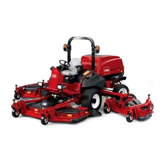
Groundsmaster
Rotary Mower
Model No. 31598—Serial No. 316000001 and Up
Model No. 31598N—Serial No. 316000001 and Up
Model No. 31599—Serial No. 316000001 and Up
Model No. 31599N—Serial No. 316000001 and Up
Form No. 3403-609 Rev A
®
5900 or 5910
*3403-609* A
Advertisement
Table of Contents

Subscribe to Our Youtube Channel
Related Manuals for Toro 31598


Summary of Contents for Toro 31598
- Page 1 Form No. 3403-609 Rev A Groundsmaster ® 5900 or 5910 Rotary Mower Model No. 31598—Serial No. 316000001 and Up Model No. 31598N—Serial No. 316000001 and Up Model No. 31599—Serial No. 316000001 and Up Model No. 31599N—Serial No. 316000001 and Up *3403-609* A Register at www.Toro.com.
- Page 2 You are responsible for operating the product properly and safely. 1. Safety-alert symbol You may contact Toro directly at www.Toro.com for product safety and operation training materials, accessory information, This manual uses 2 words to highlight information. help finding a dealer, or to register your product.
-
Page 3: Table Of Contents
Contents Engine Safety............42 Air-Cleaner Maintenance .........42 Servicing the Engine Oil..........43 Safety ................4 Adjusting the Valve Clearance ........44 General Safety............4 Fuel System Maintenance ...........44 Safety and Instructional Decals ......... 5 Servicing the Fuel System ........44 Setup ................13 Servicing the Water Separator ........45 1 Removing the Side-Deck Shipping Strap and Replacing the Fuel Filter..........45 Brace ..............13... -
Page 4: Safety
Safety Cleaning the Cab ............64 Disposing of Waste..........64 Storage ................64 This machine has been designed in accordance with ANSI Preparing for Seasonal Storage .........64 B71.4-2012. General Safety This product is capable of amputating hands and feet and of throwing objects. Always follow all safety instructions to avoid serious personal injury. -
Page 5: Safety And Instructional Decals
Safety and Instructional Decals Safety decals and instructions are easily visible to the operator and are located near any area of potential danger. Replace any decal that is damaged or lost. 93-6674 1. Crushing hazard, hand—read the instructions before 106-6754 servicing or performing maintenance. - Page 6 114-0135 1. Raise cutting units—left 3. Raise cutting units—right 2. Raise cutting units—center 132-3600 Model with Cab Only 1. Read the Operator's 5. Working light—20 A Manual for more information on fuses. 2. Headlight—25 A 6. Auxiliary power—15 A 3. Condenser fan and A/C 7.
- Page 7 114-0846 1. Read the Operators Manual; to start the engine, move the traction pedal to Neutral, apply the brake, move the throttle switch to low, turn the ignition key to Preheat. When the Wait to Start Advisory clears on the Info Center, turn the ignition key to Start.
- Page 8 114-0865 1. Height-of-cut adjustment 114-0849 114-0922 1. Warning—disengage the PTO then raise the deck. 114-0922 2. No step 1. Belt routing 3. Traction control pedal 4. Forward 5. Reverse 114-0974 114-0864 1. Belt routing 1. Height-of-cut adjustment...
- Page 9 117-4979 1. Entanglement hazard, belt—stay away from moving parts, keep all guards and shields in place. 114-4883 1. Belt routing 114-9600 1. Read the Operator's Manual. 120-6604 1. Thrown object hazard—keep bystanders away from the machine. 2. Cutting/dismemberment hazard of hand, mower blade—stay away from moving parts, keep all guards and shields in place.
- Page 10 Battery Symbols Some or all of these symbols are on your battery 1. Explosion hazard 6. Keep bystanders a safe distance from the battery. 2. No fire, open flame, or 7. Wear eye protection; smoking. explosive gases can cause blindness and other injuries.
- Page 11 114-0975 1. Height of cut 117-2754 1. Warning—read the Operator's Manual. 2. Warning—do not operate this machine unless you are trained. 3. Warning—wear the seat belt when seated in the operator's position. 4. Warning—wear hearing protection. 5. Thrown object hazard—keep bystanders a safe distance from the machine. 6.
- Page 12 121-8378 Model with Cab Only 1. Fan—off 3. Cold air 5. External air 7. Air conditioner—off 2. Fan—on full 4. Hot air 6. Internal air 8. Air conditioner—on 130-2449 1. Read the Operator’s Manual for information on maintenance.
-
Page 13: Setup
Setup Loose Parts Use the chart below to verify that all parts have been shipped. Procedure Description Qty. Remove the side-deck shipping straps – No parts required and brace. Right deck cover Left deck cover Lower the front deck winglets. V-Belt –... -
Page 14: Lowering The Front-Deck Winglets
Lowering the Front-Deck Winglets Parts needed for this procedure: Right deck cover Left deck cover V-Belt Procedure 1. Remove the nuts securing the front and rear stop bolts to the right winglet-deck mounts (Figure Figure 4 1. Winglet 4. Eccentric 2. -
Page 15: Leveling The Front, Center Deck
8. Install the winglet-deck cover and secure it with the rubber latch (Figure Note: Ensure that you slide the cover under the front, center deck-cover tabs before inserting it onto the Leveling the Winglet Decks to mounting hooks and post. the Front, Center Deck 9. -
Page 16: Preparing The Machine
Product Overview Controls Note: Determine the left and right sides of the machine from the normal operating position. Figure 8 1. Eccentric notch 4. Tighten the bolt and nut for this eccentric to 149 N·m (110 ft-lb). 5. Adjust the forward eccentric until it just makes contact with the inner slot surface of the winglet-pivot brackets. -
Page 17: Light Switch
Steering-Lever Tilt Press the lever down to tilt the steering wheel to the desired position. Release the lever to lock the adjustment (Figure Turn-Signal Switch Press the left side of the turn-signal switch to activate the left-turn signal and the right side of the switch to activate the right-turn signal (Figure Note: The center position is off. -
Page 18: Cab Controls
Cruise-Control Switch Windshield-Wiper Switch Use the windshield-wiper switch to turn the windshield The cruise-control switch sets your desired speed of the wipers to the O or O position (Figure 11). machine. Press the switch forward to engage the cruise control and Lights Switch rearward to disengage it (Figure... - Page 19 Seat-Back-Adjusting Lever 1. PTO Engaged 2. Parking Brake Engaged Move the lever to adjust the seat-back angle. 3. Fan Reversing Armrest-Adjusting Knob 4. Cruise Control Engaged Rotate the knob to adjust the angle of the armrest. 5. H/L (High/Low speed range) •...
- Page 20 Engine-Coolant-Temperature Indicator H / L (High/Low Range) Speed-Range Indicator This display indicates the temperature of the engine coolant (Figure 14). This display indicates the selected speed range (Figure 14). Air-Intake-Heater Indicator This display indicates when the system is pre heating (Figure 14).
- Page 21 Note: After you service the machine, reset the indicator. Resetting the Service-Interval Indicator 1. Press and hold the far, right button on the InfoCenter. Note: The Main Menu screen appears. 2. Select Service using the 2 buttons on the left; press the button below the right arrow to continue.
- Page 22 To Set the Cruise Control 2. Disengage the PTO. 3. Move the traction pedal to N Increase the ground speed. EUTRAL 4. Insert the jumper in teach plug. To Float the Deck 5. Engine running. Lower the decks. 6. Operator must be seated or set the parking brake. To Lower the Deck 7.
-
Page 23: Specifications
Contact your Authorized Service Dealer or Distributor or go to www.Toro.com for a list of all approved attachments and accessories. To best protect your investment and maintain optimal performance of your Toro equipment, count on Toro genuine parts. -
Page 24: Checking The Engine-Oil Level
Fuel Safety Checking the Engine-Oil Level Before you start the engine and use the machine, check DANGER the oil level in the engine crankcase; refer to Checking the In certain conditions, fuel is extremely flammable Engine-Oil Level (page 43). and highly explosive. A fire or explosion from fuel Checking the Cooling System can burn you and others and can damage property. -
Page 25: Checking The Tire Pressure
Checking the Tire Pressure • Monitor seals, hoses, and gaskets in contact with fuel as they may degrade over time. Service Interval: Before each use or daily • Fuel-filter plugging may be expected for a time after converting to biodiesel blended. The correct air pressure in the front tires is 345 kPa (50 psi ) and the rear tires is 207 kPa (30 psi) as shown in (Figure... -
Page 26: Adjusting The Height Of Cut
Adjusting the Height of Cut You can adjust the height of cut from 25 to 153 mm (1 to 6 inches) in 13 mm (1/2 inch) increments. To adjust the height of cut, position the castor-wheel axles in the upper or lower holes of the castor forks, add or remove an equal number of spacers from the castor forks, and adjust the rear chain (front deck only) to the desired holes. - Page 27 Note: When mowing at a height of cut below 51 mm Note: To prevent grass buildup between the wheel (2-1/2 inches), move the skids, gage wheels, and rollers and the fork, operate the machine at the 64 mm (2-1/2 to the highest holes. inch) height of cut or higher and install the axle bolt in the bottom caster-fork hole.
-
Page 28: Adjusting The Skids
Adjusting the Skids Adjusting the Mower Deck Anti-Scalp Rollers Mount the skids in the lower position when operating at heights of cut greater than 64 mm (2-1/2 inches) and in the Mount the mower-deck gage wheels and roller in the lower higher position when operating at heights of cut lower than position when operating at heights of cut greater than 64 mm 64 mm (2-1/2 inches). -
Page 29: Checking A Mismatch Between Mower Decks
Adjusting the Gage Wheels Matching the Height of Cut Between Mower Decks 1. Remove the bolt and nut securing the gage wheel to the mower-deck brackets (Figure 29). 1. Position the blade side to side on the outside spindle of both side mower decks. 2. -
Page 30: Adjusting The Mirrors
Adjusting the Mirrors Rear-View Mirror While sitting in the seat, adjust the rear-view mirror to attain the best view out of the rear window. Pull the lever rearward to tilt the mirror to reduce the brightness and glare of light (Figure 33). -
Page 31: Checking The Safety-Interlock Switches
Checking the Safety-Interlock Note: The engine should shut off. If it does not shut off, there is a malfunction in the interlock system that Switches you should correct before resuming operation. 5. Sit on the seat, disengage the PTO, and start the engine. CAUTION 6. -
Page 32: Starting And Stopping The Engine
Do not use the machine as a towing vehicle. to attain the desired engine speed. • Use accessories and attachments approved by The Toro® Company only. Important: Do not run the starter motor more than 30 seconds at a time or premature starter Rollover Protection System (ROPS) failure may result. -
Page 33: Understanding The Operating Characteristics
Understanding the Operating G010392 Characteristics Practice driving the machine, as it has a hydrostatic transmission, and its characteristics may differ from other turf-maintenance machines. To maintain enough power for the traction unit and implement while operating, regulate the traction pedal to keep the engine speed (rpm) high and constant. -
Page 34: After Operation
Transporting the Machine After Operation Use the transport latches when transporting the machine over long distances or rough terrain or when trailering. After Operation Safety General Safety • Clean grass and debris from the cutting units, drives, mufflers, and engine to help prevent fires. Clean up oil or fuel spills. -
Page 35: Identifying The Tie-Down Points
Identifying the Tie-Down Points Front of the machine—under the front of the operator's platform (Figure Figure 40 1. Bypass valve Figure 38 2. Rotate each valve 3 turns counter-clockwise to open 1. Front tie downs and allow oil to bypass internally. Important: Do not open the valves more than Rear of the machine—on the bumper (Figure... -
Page 36: Maintenance
Maintenance Note: Determine the left and right sides of the machine from the normal operating position. Important: Refer to your engine operator's manual for additional maintenance procedures. Recommended Maintenance Schedule(s) Maintenance Service Maintenance Procedure Interval • Torque the wheel-lug nuts. •... -
Page 37: Service Interval Chart
Maintenance Service Maintenance Procedure Interval • Adjust the valve clearance. Every 2,000 hours • Flush the cooling system and replace fluid. Every 2 years • Replace moving hoses. CAUTION If you leave the key in the ignition switch, someone could accidently start the engine and seriously injure you or other bystanders. -
Page 38: Preparing The Machine For Maintenance
If your machine requires major repairs or if you desire assistance, contact an Authorized Toro Distributor. • Use only genuine Toro replacement parts and accessories. Replacement parts and accessories made by other manufacturers could be dangerous, and such use could void the product warranty. -
Page 39: Lubrication
Lubrication Greasing the Bearings and Bushings Service Interval: Before each use or daily—Lubricate the caster-arm bushings. Every 50 hours—Lubricate all grease fittings. The machine has grease fittings that you must lubricate Figure 46 regularly with No. 2 lithium grease. Also, lubricate the 1. - Page 40 Figure 48 Figure 49 Figure 51 Figure 50...
- Page 41 Front Mower Deck Side Mower Decks (Each Side) • • 2 caster-fork-shaft bushings (Figure 4 caster-fork-shaft bushings (Figure • • 5 spindle-shaft bearings (located on the spindle housing) 3 spindle-shaft bearings (located on the spindle housing) as shown in Figure 52 as shown in Figure 54 •...
-
Page 42: Engine Maintenance
Engine Maintenance cleaning process prevents debris from migrating into the intake when you remove the primary filter. 2. Remove the primary filter (Figure 57). Engine Safety Note: Do not clean a used element due to the Shut off the engine before checking the oil or adding oil to possibility of damage to the filter media. -
Page 43: Servicing The Engine Oil
Preferred oil: SAE 15W-40 (above 0°F) • Alternate oil: SAE 10W-30 (below 23°F) Toro Premium Engine Oil is available from your distributor in either 15W-40 or 10W-30 viscosity. See the parts catalog for part numbers. Also, refer to the engine owner’s manual (included with the machine) for further recommendations. -
Page 44: Adjusting The Valve Clearance
Changing the Engine Oil Fuel System Service Interval: Every 250 hours—Change the engine oil Maintenance and filter. 1. Remove the drain plug and let the oil flow into a drain Servicing the Fuel System (Figure 61). Draining the Fuel Tank Service Interval: Every 1,000 hours—Drain and clean the fuel tank. -
Page 45: Servicing The Water Separator
Servicing the Water Separator 8. Apply a coating of clean fuel or engine oil to the new O-ring and element seal. Service Interval: Before each use or daily—Drain the water 9. Spin the bowl onto the new element, then spin them separator. -
Page 46: Electrical System Maintenance
Electrical System Maintenance Electrical System Safety • Disconnect the battery before repairing the machine. Disconnect the negative terminal first and the positive last. Connect the positive terminal first and the negative last. • Battery acid is poisonous and can cause burns. Avoid contact with your skin, eyes, and clothing. -
Page 47: Checking The Battery Condition
Rinse with clear water. Coat the battery posts and cable connectors with Grafo 112X (skin-over) grease (Toro Part No. 505-47) or petroleum jelly to prevent corrosion. -
Page 48: Charging The Battery
3. Look at the battery and identify the positive and pedal. negative battery posts. Contact your local Toro distributor or refer to the Toro Service 4. Connect the positive lead of the battery charger to the positive battery post (Figure 70). -
Page 49: Drive System Maintenance
Drive System Maintenance Adjusting the Traction-Pedal Angle You can adjust the operating angle of the traction pedal for g019500 your comfort. Figure 72 1. Loosen the 2 nuts and bolts securing the left side of the 1. Check/drain plug (3 o'clock position) traction pedal to the bracket (Figure 71). -
Page 50: Checking The Rear-Wheel Toe-In
Checking the Rear-Wheel Toe-in Service Interval: Every 1,000 hours—Check the rear-wheel toe-in. 1. Measure the center-to-center distance (at axle height) at the front and rear of the steering tires (Figure 76). Note: The front measurement cannot be more than 3 mm (0.12 inch) less than the rear measurement. -
Page 51: Cooling System Maintenance
Cooling System DANGER Maintenance The rotating fans and drive belts can cause personal injury. • Do not operate the machine without the covers Cooling System Safety in place. • Keep fingers, hands, and clothing clear of the CAUTION rotating fan and drive belt. Discharge of hot, pressurized coolant or touching a •... -
Page 52: Servicing The Engine-Cooling System
Servicing the Engine-Cooling Brake Maintenance System Adjusting the Service Brakes Service Interval: Every 100 hours—Inspect the cooling-system hoses. Adjust the service brakes when there is more than 50 mm (2 Every 2 years—Flush the cooling system and replace inches) of “free travel” of the brake pedal or when the brakes fluid. -
Page 53: Belt Maintenance
Belt Maintenance Replacing the Blade-Drive Belts Servicing the Alternator Belt Service Interval: Every 50 hours—Inspect the blade-drive belts. Service Interval: After the first 10 hours—Check the Every 1,000 hours—Replace the blade-drive belts. alternator-belt tension. The blade-drive belt, tensioned by the spring-loaded idler Every 1,000 hours—Check the alternator-belt tension. - Page 54 Figure 82 1. Hydraulic motor 2. Mounting bolts 6. Lift the motor off the mower deck and lay it on top Figure 84 of the mower deck. 1. Idler pulleys 7. Remove the old belt from around the spindle pulleys and idler pulley.
-
Page 55: Hydraulic System Maintenance
1. Perform the premaintenance procedure; refer to Preparing the Machine for Maintenance (page 38). If the Toro fluid is not available, other fluids may be used provided they meet all the following material properties 2. On the right side of the machine, raise the access cover and industry specifications. -
Page 56: Changing The Hydraulic Fluid And Filters
Contaminated fluid looks milky or black when compared to clean oil. Use Toro replacement filters (Part No. 86–6110 for the left side of the machine and 75-1310 for the right side of the machine). -
Page 57: Checking The Hydraulic Lines And Hoses
Inspecting the Hydraulic-System Test Ports The test ports are used to test the pressure in the hydraulic circuits. Contact your local Toro distributor or refer to the Toro Service Manual for assistance. Figure 90 1. Damper assembly 2. -
Page 58: Pivoting (Tilting) The Front Mower Deck Down
Adjusting the Mower-Deck Pitch Measuring the Mower-Deck Pitch The mower-deck pitch is the difference between the height-of-cut from the front of the blade plane to that of the back of the blade plane. Set a blade pitch of 7.5 mm (0.3 inch);... -
Page 59: Servicing The Castor-Arm Bushings
2. Position the shims, as required, to raise or lower the castor wheel until the mower deck has the correct pitch. 3. Install the tensioning cap. Servicing the Castor-Arm Bushings The caster arms have bushings pressed into the top and bottom of the tube, and after many hours of operation, the bushings wear. -
Page 60: Servicing The Caster Wheels And Bearings
Servicing the Caster Wheels Blade Maintenance and Bearings Blade Safety Service Interval: Every 500 hours—Inspect the mower-deck caster-wheel assemblies. DANGER 1. Remove the locknut from the bolt holding the A worn or damaged blade can break, and a piece caster-wheel assembly between the caster fork or the of the blade could be thrown at you or bystanders, caster-pivot arm (Figure... -
Page 61: Removing And Installing A Blade
Replace the blade if it hits a solid object, if it is out of balance, You must consider 2 areas of the blade when checking and or if it is bent. Always use genuine Toro replacement blades servicing it: the sail and the cutting edge. Both cutting edges to be sure of safety and optimum performance. -
Page 62: Correcting A Mower-Deck Mismatch
Miscellaneous Maintenance Servicing the Spark-Arrestor Muffler Figure 101 1. Sharpen at the original angle. Service Interval: Every 250 hours—Service the spark arrestor. Note: Sharpen only the top of the cutting edge 1. Remove the pipe plug from the clean-out port at the and maintain the original cutting angle to ensure the lower side of the muffler. -
Page 63: Cleaning The Cab Air Filters
Cleaning the Cab Air Filters 3. Install the filters and the grate with the thumb screws. Service Interval: Every 250 hours Cleaning the Air-Conditioning 1. Remove the screws and grates from both the in-cab Assembly and rear cab air filters (Figure 102 Figure 103). -
Page 64: Cleaning
B. Clean the battery, terminals, and posts with a wire brush and baking soda solution. C. Coat the cable terminals and battery posts with Grafo 112X skin-over grease (Toro Part No. 505-47) or petroleum jelly to prevent corrosion. D. Slowly recharge the battery every 60 days for 24 hours to prevent lead sulfation of the battery. - Page 65 Notes:...
- Page 66 Notes:...
- Page 67 Notes:...
- Page 68 Countries Other than the United States or Canada Customers who have purchased Toro products exported from the United States or Canada should contact their Toro Distributor (Dealer) to obtain guarantee policies for your country, province, or state. If for any reason you are dissatisfied with your Distributor's service or have difficulty obtaining guarantee information, contact the Toro importer.
Need help?
Do you have a question about the 31598 and is the answer not in the manual?
Questions and answers