Advertisement
Vision™ OPLC™
V130-33-TA24/V130-J-TA24
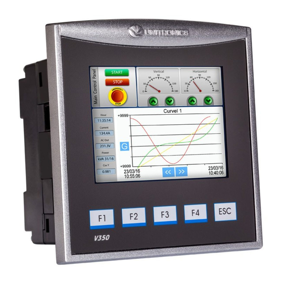
V350-35-TA24/V350-J-TA24
V430-J-TA24
General Description
All of the controllers covered in this guide are micro-OPLCs, rugged programmable logic controllers that
comprise built-in operating panels and on-board I/Os.
Item
On-board I/O
Screen
Keypad
Function Keys
Com Port, Built-in
RS232/485
USB device,
mini-B
Com Ports, separate
order, user-installed
* V430J comprises both RS232/485 and USB ports; note that only one channel may be used at a time.
Standard Kit Contents
Item
Controller
Terminal Blocks
Battery (installed)
Slides
(2 sets of key labels)
Mounting Brackets
Rubber Seal
Programming cable
+ RS232 adapter
USB
programming cable
Unitronics
Installation Guide
12 Digital Inputs, including 2 Analog,
2 PT100/TC ,1 HSC/Shaft-encoder input
10 Transistor Outputs, 2 Analog Outputs
V130-TA24
V130J-TA24
2.4"
Yes
None
Yes
None
The user may install a CANbus port (V100-17-CAN), and one of the following:
RS232/RS485 port (V100-17-RS4/V100-17-RS4X)
•
Ethernet (V100-17-ET2)
•
Profibus Slave (V100-17-PB1)
•
V130-TA24
V130J-TA24
None
Model Dependent
3.5" Color Touch
Yes
Yes
None
None
Yes
Yes
Yes
Yes (2 parts)
Yes
Yes
None
V350-TA24
V350J-TA24
None
Yes
Yes
None
V350-TA24
V350J-TA24
Yes
V430J-TA24
4.3" Color Touch
Yes*
Yes*
V430J-TA24
None
Yes (4 parts)
None
Yes
1
Advertisement
Table of Contents

Related Manuals for Vision OPLC V130-33-TA24


Summary of Contents for Vision OPLC V130-33-TA24
-
Page 1: Installation Guide
Vision™ OPLC™ Installation Guide 12 Digital Inputs, including 2 Analog, V130-33-TA24/V130-J-TA24 V350-35-TA24/V350-J-TA24 2 PT100/TC ,1 HSC/Shaft-encoder input V430-J-TA24 10 Transistor Outputs, 2 Analog Outputs General Description All of the controllers covered in this guide are micro-OPLCs, rugged programmable logic controllers that comprise built-in operating panels and on-board I/Os. -
Page 2: Environmental Considerations
Vision™ OPLC™ Installation Guide Alert Symbols and General Restrictions When any of the following symbols appear, read the associated information carefully. Symbol Meaning Description Danger The identified danger causes physical and property damage. Warning The identified danger could cause physical and property damage. -
Page 3: Panel Mounting
Vision™ OPLC™ Dimensions: V430J Panel Mounting Before you begin, note that the mounting panel cannot be more than 5 mm thick. UL listed models: To meet the UL508 standard, panel-mount the device on the flat surface of a Type 1 enclosure. - Page 4 Vision™ OPLC™ Installation Guide V430J DIN-rail Mounting (V130/V350/V130J/V350J) 1. Snap the controller onto the DIN rail as shown in the figure to the right. 2. When properly mounted, the controller is squarely situated on the DIN-rail as shown in the figure to the right.
-
Page 5: Wiring Procedure
Vision™ OPLC™ Wiring Do not touch live wires. Install an external circuit breaker. Guard against short-circuiting in external wiring. Use appropriate circuit protection devices. Unused pins should not be connected. Ignoring this directive may damage the device. Double-check all wiring before turning on the power supply. - Page 6 Vision™ OPLC™ Installation Guide Input Jumper Settings The tables below show how to set a specific jumper to change input functionality. To access the I/O jumpers, you must open the controller according to the instructions beginning on page 12. Incompatible jumper settings and wiring connections may seriously damage the controller.
- Page 7 Vision™ OPLC™ I/O Wiring npn (sink) Input Input wiring HSC input wiring pnp (source) Input Input wiring HSC input wiring Shaft-encoder Unitronics...
- Page 8 Vision™ OPLC™ Installation Guide Analog Input Analog input wiring, current (2/3-wire) Analog input wiring, current (4-wire), voltage Shields should be connected at the signal’s source. The 0V signal of the analog input must be connected to the controller’s 0V. Type Temp. Range...
-
Page 9: Power Supply
Vision™ OPLC™ Analog Outputs Transistor Outputs (pnp) The 0V signals of the transistor and the analog outputs must be connected to the controller’s 0V. Outputs 0 to 4 can be used as PWM outputs. Power Supply The controller requires an external 24VDC power supply. - Page 10 Vision™ OPLC™ Installation Guide Communication V130/V350/V130J/V350J These models comprise a built-in RS232/RS485 serial port (Port 1) V430J These models comprise built-in ports: 1 USB and 1 RS232/RS485 (Port 1). Note that physically connecting a PC to the controller via USB suspends RS232/RS485 communications via Port 1.
- Page 11 Vision™ OPLC™ Setting RS232/RS485 Communication Parameters, V130/V350/V130J/V350J This port may be set to either RS232 or RS485 via jumper. The accompanying figure shows the jumper factory default settings. These jumpers may be used to: Set communications to RS485, by setting both COMM jumpers to ‘485’.
-
Page 12: Opening The Controller
Vision™ OPLC™ Installation Guide Opening the Controller Before performing these actions, touch a grounded object to discharge any electrostatic charge. Avoid touching the PCB board directly. Hold the PCB board by its connectors. 1. Turn off the power supply, disconnect, and dismount the controller.
Need help?
Do you have a question about the OPLC V130-33-TA24 and is the answer not in the manual?
Questions and answers