Xerox CopyCentre C118 Service Manual
Hide thumbs
Also See for CopyCentre C118:
- User manual (230 pages) ,
- System administration manual (134 pages) ,
- Quick reference manual (116 pages)
Advertisement
Quick Links
Advertisement

Related Manuals for Xerox CopyCentre C118


Summary of Contents for Xerox CopyCentre C118
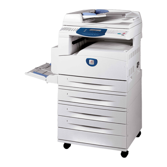
- Page 1 WorkCentre ® CopyCentre ® C118 M118/M118i copy print email Service Manual...
- Page 2 Introduction About this Manual ......................Organization........................How to Use this Documentation..................Symbology and Nomenclature ..................Translated Warnings ....................... viii Initial Issue Introduction 12/2004 CCC118, WCM118...
-
Page 3: Service Call Procedures
1 Service Call Procedures Service Call Procedures....................Initial Actions ........................Call Flow ......................... Detailed Maintenance Activities (HFSI)................Cleaning Procedures....................... Final Actions........................Initial Issue Service Call Procedures 12/2004 CCC118, WCM118... -
Page 4: Status Indicator Raps
2 Status Indicator RAPs C-Status Code H9-7000 STM Communication Failure RAP..............2-36 C1-3000 Registration Sensor On JAM RAP (Tray 1 Feed)..........J-Status Code C2-2000 Tray 2 Feed Out Sensor On JAM RAP (Tray 2 Feed)........J1-2000 Toner Cartridge Empty Failure RAP..............2-37 C2-3000 Registration Sensor On JAM RAP (Tray 2 Feed).......... - Page 5 Z-Status Code E1xxxx Sc ..2-89 E2xxxx D ..2-90 Z1-0000 Billing Counter Failure RAP ................2-65 EPxxxx EP Related RAP....................2-90 Fax Error Code ESS Failure List 00xxxx Polling Operation Error RAP ................2-67 PRINTER ESS Failure List....................2-91 01xxxx Document Feed Failure RAP ................
- Page 6 3 Image Quality Image Quality RAPs IDS 14 Light Background Due To Auto Exposure In Copies Of Originals With Frames 3-30 IDS 15 Fluctuation In Auto Exposure Values For Copies Of Originals Of Medium Density 3-31 IQ1 IOT Image Quality Entry RAP ................. IDS 16 Gradation Jump In Text &...
- Page 7 4 Repairs/Adjustments 1. Drives REP 12.1.2 Tray 4 Feeder ..................... 4-80 REP 12.3.1 Feed/Retard/Nudger Roll ................4-83 REP 1.1.1 Main Drive Assembly ..................REP 12.6.1 2TM PWB....................4-84 2. Paper Transportation REP 12.7.1 Left Lower Cover..................4-85 REP 2.2.1 Retard Pad....................13.
- Page 8 5 Parts List Overview PL 10.1 Font, Left......................5-33 PL 10.2 Rear, Right......................5-34 Introduction ........................Subsystem Information ....................11. IIT Symbology ........................PL 11.1 IIT Assembly ..................... 5-35 Parts Lists PL 11.2 IIT Unit ......................5-36 PL 11.3 IIT Under Cover Assembly................5-37 1.
- Page 9 6 General Procedures Information Entering Diagnostic Mode Cleaning Materials......................6-60 Machine Consumables....................6-60 Entering Diagnostic Mode ....................Glossary of Terms ......................6-61 Exiting Diagnostic Mode....................CE Settings ........................Change Tag Information Version ..........................Change Tag Introduction....................6-63 MC. No ..........................IOT/Processor (P) Tags ....................
- Page 10 7 Wiring Data Plug/Jack Locations Plug/Jack Locations ......................Wirenets 7.3.1 Wire Net AC POWER (HOT).................. 7-25 7.3.2 Wire Net AC POWER (NUT).................. 7-26 7.3.3 Wire Net +3.3VDC....................7-27 7.3.4 Wire Net DC COM (+3.3VRTN) ................7-28 7.3.5 Wire Net +5VDC-1 ....................7-29 7.3.6 Wire Net +5VDC-2 ....................
- Page 11 8 Accessories 8.1 Fax Kit ........................8.2 Foreign Interface ...................... 8-14 Initial Issue Accessories 12/2004 CCC118, WCM118...
- Page 12 XEROX WorkCentre M118 CopyCentre C118 service manual XEROX WorkCentre M118 CopyCentre C118 service manual XEROX WorkCentre M118 CopyCentre C118 service manual XEROX WorkCentre M118 CopyCentre C118 service manual XEROX WorkCentre M118 CopyCentre C118 service manual XEROX WorkCentre M118 CopyCentre C118 service manual...
Need help?
Do you have a question about the CopyCentre C118 and is the answer not in the manual?
Questions and answers