JVC SP-DWF10 Service Manual
Hide thumbs
Also See for SP-DWF10:
- Instructions manual (20 pages) ,
- Instructions manual (16 pages) ,
- Instructions manual (16 pages)
Advertisement
www.freeservicemanuals.info
SERVICE MANUAL
6
2004
MB251
1
PRECAUTION. . . . . . . . . . . . . . . . . . . . . . . . . . . . . . . . . . . . . . . . . . . . . . . . . . . . . . . . . . . . . . . . . . . . . . . . . 1-3
2
SPECIFIC SERVICE INSTRUCTIONS . . . . . . . . . . . . . . . . . . . . . . . . . . . . . . . . . . . . . . . . . . . . . . . . . . . . . . 1-5
3
DISASSEMBLY . . . . . . . . . . . . . . . . . . . . . . . . . . . . . . . . . . . . . . . . . . . . . . . . . . . . . . . . . . . . . . . . . . . . . . . 1-6
4
ADJUSTMENT . . . . . . . . . . . . . . . . . . . . . . . . . . . . . . . . . . . . . . . . . . . . . . . . . . . . . . . . . . . . . . . . . . . . . . . . 1-9
5
TROUBLESHOOTING . . . . . . . . . . . . . . . . . . . . . . . . . . . . . . . . . . . . . . . . . . . . . . . . . . . . . . . . . . . . . . . . . 1-10
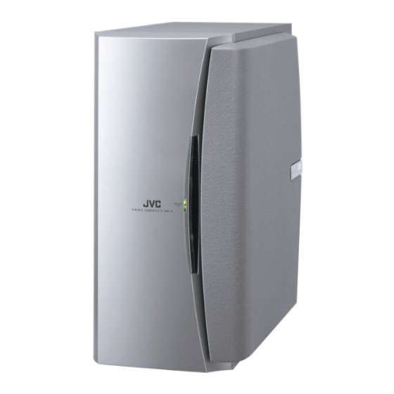
POWERED SUB WOOFER
SP-DWF10
TABLE OF CONTENTS
COPYRIGHT © 2004 Victor Company of Japan, Limited
Published in Heiloo, Holland.
Area suffix
J ---------------------------- U.S.A.
A ------------------------ Australia
E ---------- Continental Europe
US ------------------------ Singapore
UF ------------------------------ China
UP ----------------------------- Korea
UT ---------------------------- Taiwan
UX -------------------- Saudi Arabia
UJ ---------------------- U.S.Military
No.MB251
2004/6
12/6/15
Advertisement

Related Manuals for JVC SP-DWF10


Summary of Contents for JVC SP-DWF10
-
Page 1: Table Of Contents
12/6/15 SERVICE MANUAL POWERED SUB WOOFER MB251 2004 SP-DWF10 Area suffix J ---------------------------- U.S.A. A ------------------------ Australia E ---------- Continental Europe US ------------------------ Singapore UF ------------------------------ China UP ----------------------------- Korea UT ---------------------------- Taiwan UX -------------------- Saudi Arabia UJ ---------------------- U.S.Military TABLE OF CONTENTS PRECAUTION. - Page 2 www.freeservicemanuals.info 12/6/15 SPECIFICATION Type Powered Subwoofer Bass-reflex type (magnetically shielded type) 16.0 cm cone × 1 (6-5/16") Speaker Frequency Range 32 Hz 200 Hz 4 Ω Impedance Input terminals INPUT (LOW-LEVEL) Power requirements AC 120 V , 60 Hz 100 W (45 Hz, 4 Ω, 10 % THD) Output power of built-in amp Power Handling Capacity 25 W...
-
Page 3: Precaution
www.freeservicemanuals.info 12/6/15 SECTION 1 PRECAUTION Safety Precautions (1) This design of this product contains special hardware and voltmeter. many circuits and components specially for safety purpos- Move the resistor connection to each exposed metal es. For continued protection, no changes should be made part, particularly any exposed metal part having a return to the original design unless authorized in writing by the path to the chassis, and measure the AC voltage across... - Page 4 www.freeservicemanuals.info 12/6/15 Importance administering point on the safety Power switch board Caution: For continued protection against risk of fire, replace only with same type 3 A/125 V for F901. This symbol specifies the type of fast operating fuse. Precaution: Pour la protection continue contre les risques d'incendie, remplacer uniquement par le meme type: fusible 3 A/125 V pour les F901.
-
Page 5: Specific Service Instructions
www.freeservicemanuals.info 12/6/15 SECTION 2 SPECIFIC SERVICE INSTRUCTIONS This service manual does not describe SPECIFIC SERVICE INSTRUCTIONS. (No.MB251)1-5 Published in Heiloo, Holland. -
Page 6: Disassembly
www.freeservicemanuals.info 12/6/15 SECTION 3 DISASSEMBLY Removing the Amplifier assembly (See Figs.1 and 2) (1) From the back side of the main body, remove the eleven Amplifier assembly screws A attaching the amplifier assembly. (See Fig.1.) (2) Take out the amplifier assembly from the main body. (3) Disconnect the wire connector from the back side of the amplifier assembly. - Page 7 www.freeservicemanuals.info 12/6/15 Removing the power cord (See Figs.4 and 5) • Prior to performing the following procedures, remove the back panel. (1) Remove the two screws C attaching the bracket a. (See Fig.4.) (2) Pull out the bracket a toward you. (3) Disconnect the power cord from the connector CN901 the power switch board.
- Page 8 www.freeservicemanuals.info 12/6/15 Removing the net assembly (See Fig 7) (1) From side of the main body, insert the tip of the flat-bladed Flat-bladed screwdriver or similar tool into the space between the main screwdriver,etc. body and net assembly, and lift the net assembly little by little to remove.
-
Page 9: Adjustment
www.freeservicemanuals.info 12/6/15 SECTION 4 ADJUSTMENT This service manual does not describe ADJUSTMENT. (No.MB251)1-9 Published in Heiloo, Holland. -
Page 10: Troubleshooting
www.freeservicemanuals.info 12/6/15 SECTION 5 TROUBLESHOOTING This service manual does not describe TROUBLESHOOTING. 1-10 (No.MB251) Published in Heiloo, Holland. - Page 11 www.freeservicemanuals.info 12/6/15 (No.MB251)1-11 Published in Heiloo, Holland.
- Page 12 www.freeservicemanuals.info 12/6/15 Victor Company of Japan, Limited AV & MULTIMEDIA COMPANY AUDIO/VIDEO SYSTEMS CATEGORY 10-1,1chome,Ohwatari-machi,Maebashi-city,371-8543,Japan (No.MB251) Printed in Japan Published in Heiloo, Holland.
-
Page 13: Parts List
12/6/15 PARTS LIST [ SP-DWF10] * All printed circuit boards and its assemblies are not available as service parts. Area suffix J ------------------------------ U.S.A. A -------------------------- Australia E ------------ Continental Europe US ---------------------- Singapore UF ---------------------------- China UP ---------------------------- Korea... - Page 14 www.freeservicemanuals.info 12/6/15 Exploded view of general assembly and parts list Block No. Published in Heiloo, Holland.
- Page 15 www.freeservicemanuals.info 12/6/15 Published in Heiloo, Holland.
- Page 16 www.freeservicemanuals.info 12/6/15 General Assembly Block No. [M][1][M][M] Symbol No. Part No. Part Name Description Local LV21341-002A SHIELD DWF10J DWF10A,DWF10E,DWF10UF,DWF10UJ,D LV21341-001A SHIELD WF10UP,DWF10US,DWF10UT,DWF10UX LV10709-002A COVER LV30225-0R9A SPACER LV30225-0S1A SPACER (x5) LV30225-079A SPACER LV30225-0E4A SPACER LV30225-0R8A SPACER LV30225-044A SPACER QYSBSG3016E TAP SCREW M3 x 16mm(x2) QYSBSF3008Z TAP SCREW...
- Page 17 www.freeservicemanuals.info 12/6/15 Symbol No. Part No. Part Name Description Local QYSBSG3010Z TAP SCREW M3 x 10mm LV33802-001A HEAT SINK1 HS 951 E70306-001 HEAT SINK HS 954 QYSBSG3008Z TAP SCREW M3 x 8mm E70306-001 HEAT SINK HS 952 E70306-001 HEAT SINK HS 953 QYSBSG3008Z...
-
Page 18: Electrical Parts List
www.freeservicemanuals.info 12/6/15 Electrical parts list Main board Symbol No. Part No. Part Name Description Local Block No. [0][1] D1003 1SS133-T2 DIODE Symbol No. Part No. Part Name Description Local D5001 1SS133-T2 DIODE D5002 1SS133-T2 DIODE D5003 1SS133-T2 DIODE IC101 HA17558AF-X D5004... - Page 19 www.freeservicemanuals.info 12/6/15 Symbol No. Part No. Part Name Description Local Symbol No. Part No. Part Name Description Local C1028 QETN1HM-475Z E CAPACITOR 4.7uF 50V M DWF1 0UF,D C1029 NCS31HJ-470X C CAPACITOR 47pF 50V J WF10 C1030 QEKC1HM-475Z E CAPACITOR 4.7uF 50V M UJ,D C1031...
- Page 20 www.freeservicemanuals.info 12/6/15 Symbol No. Part No. Part Name Description Local Symbol No. Part No. Part Name Description Local C9502 QCZ0366-102 C CAPACITOR 1000pF R1061 NRSA63J-105X MG RESISTOR 1MΩ 1/16W J C9503 NCB31HK-471X C CAPACITOR 470pF 50V K R1062 QRE141J-470Y C RESISTOR 47Ω...
- Page 21 www.freeservicemanuals.info 12/6/15 Symbol No. Part No. Part Name Description Local Symbol No. Part No. Part Name Description Local DWF1 R9529 QRE141J-753Y C RESISTOR 75kΩ 1/4W J 0J,D VR501 QVP0008-502Z TRIM RESISTOR 5kΩ R5063 NRSA02J-150X MG RESISTOR 15Ω 1/10W J WF10 VR502 QVP0008-203Z...
- Page 22 www.freeservicemanuals.info 12/6/15 Packing materials and accessories parts list Block No. A1 A3 A6 US, UJ A1 A2 A3 A1A3 A5 A, E, UP, UT, UX A1 A3 A1 A2 A3 A11A12 A8 A9 3-10 Published in Heiloo, Holland.
- Page 23 www.freeservicemanuals.info 12/6/15 Packing and Accessories Block No. [M][3][M][M] Symbol No. Part No. Part Name Description Local LVT1145-007A INST BOOK DWF10A LVT1145-002C INST BOOK GER FRE DUT SPA ITA SWE FIN DAN DWF10E LVT1145-010A INST BOOK DWF10J LVT1145-009A INST BOOK CHI(PEKIN) DWF10UF LVT1145-006A...
- Page 24 12/6/15 SCHEMATIC DIAGRAMS POWERED SUBWOOFER SP-DWF10 CD-ROM No.SML200406 Area suffix J ---------------------------- U.S.A. A ------------------------ Australia E ---------- Continental Europe US ------------------------ Singapore UF ------------------------------ China UP ----------------------------- Korea UT ---------------------------- Taiwan UX -------------------- Saudi Arabia UJ ---------------------- U.S.Military...
- Page 25 www.freeservicemanuals.info 12/6/15 In regard with component parts appearing on the silk-screen printed side (parts side) of the PWB diagrams, the parts that are printed over with black such as the resistor ( ), diode ( ) and ICP ( ) or identified by the " " mark nearby are critical for safety.
-
Page 26: Block Diagram
www.freeservicemanuals.info 12/6/15 Block diagram Volume board Amp board SPEAKER RY502 IC505 IC506 Q5006 INV. DRV. Q5007 IC503 IC501 IC502 IC504 MUTE Amp. Comparator Driver IC571 Q5706 INV. VR501 VR502 Off set Carrier Freq. CN861 REGULATOR Q5902 Q5903 Q5904 Q5905 GREEN INDICATOR CN502 CN951... - Page 27 www.freeservicemanuals.info 12/6/15 Standard schematic diagram CN861 R8601 R5034 R5021 D8601 D8602 IC503 TC74HC00AF-W Parts are safety assurance parts. R5028 SPR325MVW R5003 R5011 D5003 When replacing those parts make R5013 sure to use the specified one. 1SS133 R5036 4.7k Q5001 2SA1037AK IC501 IC502 HA17558AF-X...
- Page 28 www.freeservicemanuals.info 12/6/15 Printed circuit boards Main board (Switch board) (Amp. board) CN505 R5905 D5716 R5911 CN101 D5013 C5907 C5909 C5711 D1003 C5024 L5903 D1002 Q5904 D5911 R1016 Q5905 RY502 D5703 C5023 R5747 CN102 L5904 R5914 R5906 TH501 L5902 R5057 Q5903 C5908 R5702 R5912...
- Page 29 www.freeservicemanuals.info 12/6/15 Main board (Regulator board) EP951 C9512 C9511 C9509 R9518 R9522 C9508 C9507 Q9508 Q9509 R9519 R9523 D9510 D9509 R9526 R9525 Q9510 HS953 HS952 T9501 R9524 R9527 PC951 R9508 R9504 D9506 R9510 D9504 R9529 R9528 IC951 R9503 R9501 W9002 R9502 C9503 W9001...
- Page 30 www.freeservicemanuals.info 12/6/15 < M E M O > Published in Heiloo, Holland.
- Page 31 www.freeservicemanuals.info 12/6/15 Victor Company of Japan, Limited AV & MULTIMEDIA COMPANY AUDIO/VIDEO SYSTEMS CATEGORY 10-1,1chome,Ohwatari-machi,Maebashi-city,371-8543,Japan Printed in Japan (No.MB251SCH) Published in Heiloo, Holland.
Need help?
Do you have a question about the SP-DWF10 and is the answer not in the manual?
Questions and answers