Table of Contents
Advertisement
Quick Links
Advertisement
Table of Contents

Subscribe to Our Youtube Channel
Related Manuals for Arcom SBC-GX1


Summary of Contents for Arcom SBC-GX1
- Page 1 SBC-GX1 Technical Manual company www.arcom.com...
- Page 2 This product is supplied with a full 3 year warranty. Product warranty covers failure caused by any manufacturing defects. Arcom will make all reasonable effort to repair the product or replace it with an identical variant. Arcom reserves the right to replace the returned product with an alternative variant or an equivalent fit, form and functional product.
-
Page 3: Table Of Contents
SBC-GX1 ‘at a glance’ ......................7 Features..........................8 SBC-GX1 support products ....................10 Handling your board safely ....................11 Conventions .........................12 Getting started with your SBC-GX1 ....................13 CPU configuration........................13 Installing memory.........................13 Connecting a floppy disk drive .....................14 Connecting a hard disk drive ....................14 Connecting a CD-ROM (IDE Type) ..................14 Using the CompactFlash socket ..................15... - Page 4 SBC-GX1 Technical Manual Contents Boot disk ..........................53 Operating System drivers ........................54 Windows 98 driver support ....................54 Windows NT4.0 Driver Support ...................58 Other software support ......................60 Hardware support ..........................61 Detailed hardware description ......................62 SBC-GX1 block diagram......................62 Processor..........................63 Memory ..........................63 Static RAM ...........................66 Memory map ........................66...
- Page 5 Appendix A – Contacting Arcom.......................82 Appendix B – Connector details.......................83 Appendix C – Specification ......................95 Appendix D – SBC-GX1 mechanical diagram .................96 Appendix E – TFT display interface cable..................97 Appendix F – Reference information ....................98 Appendix G – Display Converter 1 (DC1) ..................100 Index ..............................
-
Page 6: Introduction
GX1 300MHz CPU, No DRAM, 16M Flash • SBC-GX1-M32-F16 AMD Geode GX1 300MHz CPU, 32M DRAM, 16M Flash. The SBC-GX1 can also be supplied with other DRAM options up to 256MB. Please contact Arcom for details. © 2004 Arcom Issue D... -
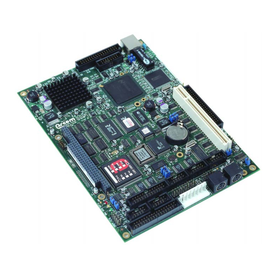
Page 7: Sbc-Gx1 'At A Glance
SBC-GX1 Technical Manual Introduction SBC-GX1 ‘at a glance’ EBX power supply connector COM4 RS422/485 serial port Floppy disk interface COM4 RS232 port Gen. purpose I/O Parallel port interface COM2 RS232 serial port PS/2 mouse PS/2 keyboard COM1 RS232 USB serial port... -
Page 8: Features
SBC-GX1 Technical Manual Introduction Features • AMD Geode GX1 300MHz MMX-enhanced processor. Chipset • AMD CS5530A I/O Companion. Cache • 16K L1 write-back cache. BIOS • Award Software PCI Plug and Play BIOS or General Software Embedded BIOS 2000. •... - Page 9 SBC-GX1 Technical Manual Introduction Parallel port • High speed parallel port SPP/EPP/ECP mode. • BIOS Configurable. Serial ports • Four 16C550 compatible high speed UARTs. • 3 x RS232 and 1 x RS232/422/485 Interfaces. USB interface • Two Universal Serial Bus (USB) interfaces.
-
Page 10: Sbc-Gx1 Support Products
SBC-GX1. The TSC1 is designed to directly interface between either 4, 5 or 8-wire analog touchscreens and a serial connection. A 1:1 ribbon cable can be used to connect directly to one of the RS232 ports on the SBC-GX1 and a separate +5V connection is also required. For more details go to www.arcom.com... -
Page 11: Handling Your Board Safely
When disposing of the board or battery, take appropriate care. Do not incinerate, crush or otherwise damage the battery. Packaging Please ensure that should a board need to be returned to Arcom, it is adequately packed, preferably in the original packing material. Electromagnetic compatibility (EMC) -
Page 12: Conventions
SBC-GX1 Technical Manual Introduction Conventions The following symbols are used in this guide: Symbol Explanation Note - information that requires your attention. Tip - a handy hint that may provide a useful alternative or save time. Caution – proceeding with a course of action may damage your equipment or result in loss of data. -
Page 13: Getting Started With Your Sbc-Gx1
In this section we guide you through setting up and using some of the features of the SBC-GX1. If you would like more detailed information on any aspect of the board refer to the Detailed hardware description section beginning on page 62. -
Page 14: Connecting A Floppy Disk Drive
10 to 16 on this connector. Connecting a hard disk drive Up to two IDE hard disk drives can be supported by the SBC-GX1. Both drives should be connected to PL2 via a 40 way 1:1 ribbon cable. The primary drive should be setup as a ‘master’... -
Page 15: Using The Compactflash Socket
Connecting a printer An enhanced printer port is incorporated onto the SBC-GX1. This port can be used to support a Centronics-compatible printer or ECP/EPP bi-directional device. The signals are routed to a 26-way boxed header and the pin assignment has been arranged to allow 1:1 connection with a 25-way IDC D-Type socket. -
Page 16: Using The Flat Panel Interface
SBC-GX1 development kit. The development kit also contains the associated cable to enable connection of the display. If you wish to use this display then connect it to the SBC-GX1 via the flat panel interface connector PL15. -
Page 17: Using The Usb Ports
I/O address, IRQ and DMA settings do not conflict with any devices on the SBC-GX1. If you are using a PC/104 card that requires +5V, this is automatically supplied via the PC/104 header. -
Page 18: Jumpers And Connectors
SBC-GX1 Technical Manual Jumpers and connectors Jumpers and connectors The following diagram shows the jumpers and connectors on the front of the SBC-GX1. Click on any jumper or connector for information. PL8 PL10 PL13 PL16 PL17 PL12 PL14 PL18 PL19... - Page 19 SBC-GX1 Technical Manual Jumpers and connectors The following diagram shows the connectors on the back of the SBC-GX1: DIMM1 PL25 (SODIMM socket) (CompactFlash connector) © 2004 Arcom Issue D...
-
Page 20: Jumpers
SBC-GX1 Technical Manual Jumpers and connectors Jumpers There are twelve user-selectable jumpers on the SBC-GX1. Further details are provided about each of these below. The diagram indicates the default position for each link. Jumper Description Watchdog timer timeout selection Watchdog timer enable... - Page 21 SBC-GX1 Technical Manual Jumpers and connectors LK3 – LCD backlight supply voltage Used to select the LCD backlight supply voltage (BLKSAFE). There are two options available: +5V or +12V. Description +5V backlight Default setting: +12V backlight If +12V is selected, this voltage must be supplied from an external source via the power connector PL12 pin 4.
- Page 22 SBC-GX1 Technical Manual Jumpers and connectors LK6 – COM3 IRQ routing Used to select which IRQ signal is connected to the COM3 serial port. Description IRQ4 Default setting: IRQ11 LK7 – Clear CMOS/battery disable A battery link is fitted that is used to prevent drain on the battery during shipment.
- Page 23 Jumpers and connectors LK11 & LK12 – User jumpers These two jumpers are user-configurable. They have no function on the SBC-GX1, but can be used by an application program to signify a configuration setting. The position of these jumpers can be read via the special function I/O register at address 259H. See...
-
Page 24: Connectors
SBC-GX1 Technical Manual Jumpers and connectors Connectors There are twenty five connectors on the SBC-GX1 that let you connect external devices such as keyboards, floppy disk drives, hard disk drives, printers etc. Detailed pin assignments are shown in Appendix B – Connector details. -
Page 25: Award Bios Setup
Award BIOS setup Award BIOS setup The SBC-GX1 is normally supplied with an Award Software BIOS. This section explains how to use the CMOS Setup Utility to modify the Award BIOS configuration. In order to support Windows CE. NET and Windows XP Embedded, the SBC- GX1 requires a General Software Embedded BIOS 2000. -
Page 26: The Main Menu
SBC-GX1 Technical Manual Award BIOS setup The Main menu When you launch the Award BIOS CMOS Setup Utility, the Main Menu is displayed: ROM PC/ISA BIOS (2A434001) CMOS Setup Utility Award Software, Inc. Standard CMOS Setup Integrated Peripherals BIOS Feature Setup... - Page 27 SBC-GX1 Technical Manual Award BIOS setup Option Explanation Load BIOS Defaults Used to revert to the original factory-assigned BIOS settings. These are the most stable values for the system. Use them if the system is performing erratically due to hardware problems.
- Page 28 SBC-GX1 Technical Manual Award BIOS setup Please note the following: • A description of the option currently highlighted is displayed at the bottom of the screen. • You can press F1 to pop up a help window listing the keys available and the selections that can be made for the highlighted item.
-
Page 29: Control Keys
SBC-GX1 Technical Manual Award BIOS setup Control keys The following keys are available while using the Award BIOS CMOS Setup utility: Explanation Moves to previous item. Moves to next item. Moves to the item on the left. Moves to the item on the right. -
Page 30: Standard Cmos Setup
SBC-GX1 Technical Manual Award BIOS setup Standard CMOS setup The items in the Standard CMOS Setup Menu are divided into several categories, each of which contains one or more than one setup item. ROM PC/ISA BIOS (2A434BI0) Standard CMOS Setup Award Software, Inc. -
Page 31: Bios Features Setup
SBC-GX1 Technical Manual Award BIOS setup BIOS features setup The options in the BIOS Feature Setup screen let you configure the BIOS features: ROM PCI/ISA BIOS (2A434001) BIOS FEATURE SETUP AWARD SOFTWARE, INC CPU Internal Cache Enabled Video BIOS Shadow... - Page 32 SBC-GX1 Technical Manual Award BIOS setup The following table explains the settings you can choose: Field Explanation CPU Internal Depending on the CPU/chipset design, enabling this option can Cache speed up memory access. The default value is ‘enabled’. If set to ‘Enable’, some of the checks in the Power On Self Test...
- Page 33 SBC-GX1 Technical Manual Award BIOS setup Field Explanation Security Option Lets you limit access to either the system and the Setup utility, or just the Setup utility. Choose: • System – you must enter a password before the system will launch, or to enter the Setup utility.
-
Page 34: Chipset Features Setup
SBC-GX1 Technical Manual Award BIOS setup Chipset features setup The Chipset Feature Setup menu is optimized for the SBC-GX1 board. The following options are available: ROM PCI/ISA BIOS (2A434001) CHIPSET FEATURE SETUP AWARD SOFTWARE, INC SDRAM CAS Latency Time AUTO CPU Warning Temperature : 100°C/212°F... - Page 35 SBC-GX1 Technical Manual Award BIOS setup Field Explanation SDRAM Clock Ratio Div Used to set the SDRAM interface speed. The options are divide by 4 or divide by 3. The divide by 4 setting sets the SDRAM interface to 75MHz and divide by 3 sets it to 100MHz.
-
Page 36: Power Management
SBC-GX1 Technical Manual Award BIOS setup Power management The settings in the Power Management Setup screen determine the power the system consumes. ROM PCI/ISA BIOS (2A434001) POWER MANAGEMENT SETUP AWARD SOFTWARE, INC. Power Management Disabled IRQ1 (Keyboard) IRQ3 (COM2) **PM Timers**... - Page 37 Enables the RTC Alarm to wake the system up from sleep mode. Soft-OFF by PWR-BTN This function is not supported on the SBC-GX1. IRQ1, IRQ2, IRQ4 to These functions allow the corresponding IRQ to be selected IRQ7, IRQ9 to IRQ15 as a wake up event.
-
Page 38: Pnp / Pci Configuration Setup
SBC-GX1 Technical Manual Award BIOS setup PNP / PCI configuration setup The settings in the PNP/PCI Configuration screen determine the IRQ resources for the system. ROM PCI / ISA BIOS (2A434001) PNP / PCI CONFIGURATION AWARD SOFTWARE, INC. PNP OS Installed... -
Page 39: Integrated Peripherals
SBC-GX1 Technical Manual Award BIOS setup Integrated peripherals ROM PC/ISA BIOS (2A434001) INTEGRATED PERIPHERALS AWARD SOFTWARE, INC. IDE HDD Block Mode Enabled ECP mode User DMA Primary IDE Channel Enabled Build in CPU Audio Enabled Master Drive PIO Mode :... - Page 40 Selects the configuration for supporting more than one VGA adapter card. This feature can be used to set the default display when a secondary PCI VGA adapter is used with the SBC-GX1. Video Memory Size The video memory is shared with the main system memory and can be set to 1.5MB, 2.5MB or 4MB.
- Page 41 SBC-GX1 Technical Manual Award BIOS setup Field Description Display Status Used to select the default display type. The options available are CRT, LCD or Both. The default setting is Both. Flat Panel Type Used to configure the LCD interface output for the desired display resolution.
-
Page 42: General Software Embedded Bios 2000
General Software Embedded BIOS 2000 General Software Embedded BIOS 2000 If you require support for Windows CE.NET or Windows XP Embedded, the SBC-GX1 can be supplied with a General Software Embedded BIOS 2000. This section explains how to use the CMOS Setup Utility to modify the General Software Embedded BIOS 2000 configuration. -
Page 43: The Main Menu
SBC-GX1 Technical Manual General Software Embedded BIOS 2000 The Main menu When you launch the General Software Embedded BIOS 2000 Setup utility, the Main Menu is displayed: System Bios Setup - Utility v5.0 (C) 2001 General Software, Inc. All rights reserved >Basic CMOS Configuration... - Page 44 SBC-GX1 Technical Manual General Software Embedded BIOS 2000 Option Explanation Reset CMOS to factory Restores the CMOS values to the hard-coded factory settings. This is the same as removing the battery link. defaults Write to CMOS and Exit Saves any changes made to the CMOS, and exits the CMOS Setup utility.
-
Page 45: Control Keys
SBC-GX1 Technical Manual General Software Embedded BIOS 2000 Control keys The following keys are available while using the General Software Embedded BIOS 2000 Setup utility: Effect Moves to previous item. Moves to next item. Moves to the item on the left. -
Page 46: Basic Cmos Configuration Screen
BIOS will attempt to load and execute a Windows CE Kernel file (NK.BIN), from the root directory of a selected drive. Boot order Determines the order that the SBC-GX1 will attempt to boot from a drive. Set this to your required boot order. If a valid boot record is not found on the first drive, the BIOS will attempt to boot from the next drive in the list. - Page 47 • IDE 3 - IDE Secondary Slave Device (not used). To use the primary IDE drive on the SBC-GX1, configure IDE 0 in the ATA DRV Assignment section, map IDE 0 to drive C: in the Drive assignment order section, and set the required Boot order.
- Page 48 SBC-GX1 Technical Manual General Software Embedded BIOS 2000 Field Explanation Show “Hit Del” Determines whether the prompt to ‘Hit Del for setup’ is displayed during the POST. Config Box Determines whether the configuration screen is displayed at the end of the POST.
-
Page 49: Custom Configuration Screen
Field Explanation Standby mode Used to specify whether the BIOS should put the SBC-GX1 board into a low power Standby mode if there is no activity. If you enable this feature, you can choose to put the board into power down after 1, 2, 5, 10, 15, or 30 seconds, or 1, 2, 5, 10, 15 mins, or 30 mins, or 1, 2 or 5 hours. - Page 50 SBC-GX1 Technical Manual General Software Embedded BIOS 2000 Field Explanation XpressAudio The AMD Geode GX1 can be used to emulate a Soundblaster- 16 by enabling this feature. If the XpressAudio feature is enabled, the I/O base, IRQ and DMA settings need to be configured. The options available are: •...
-
Page 51: Shadow Configuration Setup Screen
SBC-GX1 Technical Manual General Software Embedded BIOS 2000 Shadow configuration setup screen This screen lets you enable and disable the shadowing of areas of ISA ROM regions. Normally shadowing should be enabled at E000-F000 to maximize system ROM BIOS performance, and any other region that a ROM BIOS extension may be executed from. -
Page 52: Software Support
CD. Datalight ROM-DOS 6.22 If your SBC-GX1 board is fitted with flash memory it will be supplied with a license for Datalight's ROM-DOS 6.22 operating system. This operating system will be pre- installed on the flash drive. -
Page 53: Flashrom Utility
This utility may also be used to provide more support for flat panel displays. The default BIOS on the SBC-GX1 supports some built-in display configurations and these may not be suitable for your application. Please contact Arcom if you need support that is not in the standard BIOS. -
Page 54: Operating System Drivers
SBC-GX1 Technical Manual Operating System drivers Operating System drivers The support CD contains drivers for XpressGraphics , XpressAudio , PCI Bridge, UDMA Bus mastering IDE controller and DP83815 Ethernet controller. The following sections provide details for installing these drivers for Windows 98 and NT4. The CD also contains drivers for some other operating systems - See the documentation on the CD for more details. - Page 55 SBC-GX1 Technical Manual Operating System drivers XpressAUDIO audio driver In the Control Panel, select System → Device Manager and choose Other Devices. Select PCI Multimedia Audio Device and click on Properties. Select the Driver tab and click on Update driver.
- Page 56 SBC-GX1 Technical Manual Operating System drivers Select Other location. Select the path D:\Win98\Ethernet and click on OK. The file ‘NET83815.INF’ will be found. Wait while the driver installs. Insert the Windows 98 CD-ROM if prompted. If Windows complains it can’t find a file on the CD-ROM, click on Skip File.
- Page 57 SBC-GX1 Technical Manual Operating System drivers ACPI bridge In the Control Panel, select System → Add New Hardware. Select PCI Bridge. Select Reinstall Driver and click on Next. Select Display a list of all drivers and click on Next. Click on Have Disk.
-
Page 58: Windows Nt4.0 Driver Support
SBC-GX1 Technical Manual Operating System drivers Windows NT4.0 Driver Support Before installing Windows NT 4.0, power up the board and enter the Setup utility by pressing the Del key during the POST. In the BIOS features screen set the boot sequence to CD-ROM, C, A. - Page 59 SBC-GX1 Technical Manual Operating System drivers Specify the I/O, IRQ and DMA settings (the driver does not auto-detect them. These must be identical to the settings specified in the BIOS features setup screen in the Setup utility (see page 31). The default settings are:...
-
Page 60: Other Software Support
SBC-GX1 Technical Manual Operating System drivers Other software support The support CD also contains the following material: • Microsoft Internet Explorer 5.0 • Mitsumi mouse driver (For DOS) • Adobe Acrobat Reader 4.05 • Example source code for: General purpose I/O. -
Page 61: Hardware Support
Hardware support Hardware support As the SBC-GX1 is a fully compatible PC/AT processor board. Any standard PC reference guide will provide information on hardware aspects of the board. The following material has been included on the support CD as it relates to specific features of the board which may not be available from other sources. -
Page 62: Detailed Hardware Description
Detailed hardware description The following section provides a detailed description of the functions provided by the SBC-GX1. This information may be required during development once you have started adding extra peripherals or are starting to use some of the embedded features. -
Page 63: Processor
The GX1 is a 64-bit x86 compatible device and has 16K L1 write-back cache integrated into the processor. The device also contains an integrated floating point unit. A 300MHz part is used on the SBC-GX1, this part is supplied with a 33MHz clock signal and multiplied within the device. - Page 64 Flash memory The SBC-GX1 board supports up to 16MB flash memory. This memory is configured to be a read/write silicon disk drive. The Datalight FlashFX flash filling system is automatically loaded during the POST routine to enable the flash drive to be accessed.
- Page 65 SBC-GX1 Technical Manual Detailed hardware description 258H I/O Write Bit No. Paged address register 0 Address bit A14 Address bit A15 Address bit A16 Address bit A17 Address bit A18 Address bit A19 Address bit A20 Address bit A21 259H I/O Write Bit No.
-
Page 66: Static Ram
Detailed hardware description Static RAM The SBC-GX1 is designed to support a 128K byte static RAM device. This device is decoded using the same memory window as the Flash disk. Selection between Flash and SRAM is achieved by setting bit 6 in I/O register 259H. If this bit is set to ‘logic 0’... -
Page 67: I/O Map
64K I/O address range of the processor. The following table shows the I/O address mapping for the SBC-GX1. If expansion boards are added via the PC/104 interface you should ensure that they are configured to be at a free address location. -
Page 68: Graphics Controller
SBC-GX1 Technical Manual Detailed hardware description Graphics controller The AMD Geode GX1 processor contains a high performance graphics controller. With the support of the CS5530, this can be used to drive TFT LCD flat panel and CRT displays simultaneously. The graphics controller is supported by a fully PC compatible video BIOS which enables it to support all standard VGA and XGA graphics modes. - Page 69 VGA compatible CRT monitor. A suitable cable is provided as part of the SBC-GX1 development kit. The following table shows the connection details for this cable. The CRT signals may be affected by noise and therefore this cable should be kept as short as possible and should be routed away from other signals to stop any crosstalk.
-
Page 70: Interrupt Assignments
The support CD contains drivers for Windows 98 and NT 4.0. Interrupt assignments The SBC-GX1 contains two 8259 interrupt controllers, which are cascaded in the standard PC/AT compatible format. The table below shows the IRQ routing of the on-board devices. -
Page 71: Dma Controller
DMA controller There are two 8237 DMA controllers on the SBC-GX1. These are cascaded in a standard PC/AT style. DMA channels 0-3 are used to support 8-bit devices and DMA channels 4-7 support 16-bit devices. -
Page 72: Ide Interface
The secondary controller is used to support a compact flash card interface. The CompactFlash socket PL25 is mounted on the underside of the SBC-GX1. This socket can be used to support both Type I and Type II CompactFlash cards. The CompactFlash card can be used to replace a mechanical drive in the system. -
Page 73: Real Time Clock
SBC-GX1 Technical Manual Detailed hardware description Real time clock The Real time clock is fully compatible with the PC/AT standard clock device. The date and time functions are stored in the real time clock when the main power is removed as long as the battery backup supply is enabled (see description). -
Page 74: 16-Bit Soundblaster
These are stored in the Ethernet directory. 16-bit SoundBlaster The audio support provided by the SBC-GX1 is fully compatible with the 16-bit SoundBlaster interface. This device provides support for stereo line in and line out and mono Microphone input. The SoundBlaster is supported via the XpressAudio software which is built into the BIOS code. -
Page 75: User Jumpers
Detailed hardware description User jumpers There are two user jumpers on the SBC-GX1 - LK11 and LK12. The status of these user jumpers can be read via I/O address 259H bits 1 and 2 respectively. If the link is made then the corresponding bit is read as a logic ‘0’. (See the... -
Page 76: General Purpose I/O
Detailed hardware description General purpose I/O Eight general purpose I/O lines are provided on the SBC-GX1. These lines are routed to a 20-way 0.1” header PL13. The header provides un-buffered and buffered versions of the lines. The buffered version can be used to drive higher output current (up to 24mA per output) than the un-buffered version. -
Page 77: Cpu Temperature Sensor
SBC-GX1 Technical Manual Detailed hardware description CPU temperature sensor An National Semiconductor LM84 temperature monitor IC is fitted to the board. This device can be used to monitor the CPU die temperature and the board temperature. It provides feedback if the temperature rises above a predefined level. The LM84 has an C bus interface and is connected to three I/O lines. -
Page 78: Pci Bus Interface
Serial ports There are four high speed 16550 serial UART’s on the SBC-GX1. All four channels are fully software compatible with the 16550 and can be used as standard RS232 serial interfaces. The table below shows the configuration for each channel:... -
Page 79: Rs422
This enables the serial communications software to detect that all data has been sent and disable the transmitter when required. LK8 should be made to enable the RS485 interface. LK9 and LK10 should be made if the SBC-GX1 is at the end of the network. -
Page 80: Power Supply
Detailed hardware description Power supply The SBC-GX1 is designed to operate from a single +5V ± 5% (4.75V to +5.25V) supply. The power connector PL12 has two +5V connection and three ground connections. These connections are connected on board. PL12 also has a +12V connection defined. -
Page 81: Status Led's
SBC-GX1 Technical Manual Detailed hardware description Status LED’s There are three status LED’s on-board: Colour Name Illuminates… Flash Access Each time the flash array is accessed this LED illuminate. Green Power On during normal operation. Yellow Suspend On during Suspend Mode. (The Power LED is also extinguished.) -
Page 82: Appendix A - Contacting Arcom
Appendix A – Contacting Arcom Appendix A – Contacting Arcom Arcom sales Arcom’s sales team is always available to assist you in choosing the board that best meets your requirements. Contact your local sales office or hotline. Sales office US... -
Page 83: Appendix B - Connector Details
SBC-GX1 Technical Manual Appendix B – Connector details Appendix B – Connector details PL1 - Auxiliary header Connector: 6-way, 2.54mm (0.1”) x 2.54mm (0.1”) dual row header. Mating Connector: Framatome 65043-034 Signal Name Signal Name Speaker Negative Speaker Positive Reset Input... - Page 84 SBC-GX1 Technical Manual Appendix B – Connector details PL3 – Ethernet Status LEDs Connector: 4-way, 2.54mm (0.1”) single row header. Mating Connector: Framatome 65240-004 Signal Name 100Mbps 10Mbps LINK PL4 - PCI connector Connector: 120-way PCI Card edge connector (5V 32-bit 33MHz PCI socket)
- Page 85 SBC-GX1 Technical Manual Appendix B – Connector details PL5 - Ethernet RJ45 Connector: Molex 9540-2881 Mating Connector: Molex 87522 Signal Name No Connect No Connect No Connect No Connect PL6 – COM3 RS232 serial port Connector: 10 way, 2.54mm (0.1”) x 2.54mm (0.1”) boxed header...
- Page 86 SBC-GX1 Technical Manual Appendix B – Connector details PL7 - PS/2 keyboard Connector: 6-pin Mini-DIN. Signal Name KB DATA No Connect Ground KB CLOCK No Connect PL8 - USB ports Connector: 10 way, 2.54mm (0.1”) x 2.54mm (0.1”) dual row pin header...
- Page 87 SBC-GX1 Technical Manual Appendix B – Connector details PL10 – COM4 RS232 serial port Connector: 10 way, 2.54mm (0.1”) x 2.54mm (0.1”) boxed header Mating Connector: Framatome 71600-010 Pin (10-way Pin (9-way header) Signal Name D-type plug) Data Carrier Detect (DCD)
- Page 88 SBC-GX1 Technical Manual Appendix B – Connector details PL12 - Power connector Connector: 7-pin locking power connector, Molex part number 26-60-4070. Mating Connector: Molex 09-91-0700 Signal Name Ground Ground +12V +3.3V (Not Used) Ground PL13 - General purpose I/O lines Connector: 20 way, 2.54mm (0.1”) x 2.54mm (0.1”) dual row pin header...
- Page 89 SBC-GX1 Technical Manual Appendix B – Connector details PL15 -VGA CRT connector Connector: 16 way, 2.54mm (0.1”) x 2.54mm (0.1”) boxed header Mating Connector: Framatome 71600-016 Signal Name Signal Name Ground GREEN No Connect BLUE Ground +5V (Fused) No Connect...
- Page 90 SBC-GX1 Technical Manual Appendix B – Connector details PL17 - Floppy disk interface Connector: 34 way, 2.54mm (0.1”) x 2.54mm (0.1”) boxed header Mating Connector: Framatome 71600-034 Signal Name Signal Name Ground DENSEL Ground DRATE Ground /INDEX Ground /MTR0 Ground...
- Page 91 SBC-GX1 Technical Manual Appendix B – Connector details PL19 – COM1 RS232 serial port Connector: 10-way, 2.54mm (0.1”) x 2.54mm (0.1”) boxed header Mating Connector: Framatome 71600-010 Pin (10-way Pin (9-way header) Signal Name D-type plug) Data Carrier Detect (DCD)
- Page 92 SBC-GX1 Technical Manual Appendix B – Connector details Row A Row B Row C Row D /IOR /DACK7 /DACK3 DRQ7 DRQ3 DACK1 MASTER DRQ1 Ground /REFRESH Ground SYSCLK IRQ7 IRQ6 IRQ5 IRQ4 IRQ3 /DACK2 BALE Ground Ground Ground PL21 – Flash access LED Connector: 2-way, 2.54mm (0.1”) single row header...
- Page 93 SBC-GX1 Technical Manual Appendix B – Connector details PL22 – In-system-programming header This connector is used at assembly time only PL24 - 16-bit SoundBlaster Connector: 10-way, 2.54mm (0.1”) x 2.54mm (0.1”) dual row pin header Mating Connector: Framatome 71600-010 Signal Name...
- Page 94 SBC-GX1 Technical Manual Appendix B – Connector details Signal Name Signal Name /IOCS16 /CD2 /CD1 /CS1 /VS1 /IORD /IOWR INTRQ /CSEL /VS2 /RESET IORDY /INPACK /REG /DASP /PDIAG Ground © 2004 Arcom Issue D...
-
Page 95: Appendix C - Specification
SBC-GX1 Technical Manual Appendix C – Specification Appendix C – Specification AMD Geode™ GX1 MMX-enhanced processor. Memory 16MB, 32MB, 64MB, 128MB, 256MB 3.3V un-buffered SDRAM. 144-pin SODIMM Module. 4MB, 8MB, 16MB Intel StrataFlash 256KB Flash BIOS EPROM, 128KB SRAM – factory fit option... -
Page 96: Appendix D - Sbc-Gx1 Mechanical Diagram
SBC-GX1 Technical Manual Appendix D – SBC-GX1 mechanical diagram Appendix D – SBC-GX1 mechanical diagram 0.00 0.00 5.08 5.08 6.35 14.60 17.14 72.39 73.66 76.20 82.68 87.63 92.71 93.98 138.43 149.86 152.40 158.75 PL21 167.00 PL16 PL14 PL10 173.99 PL18 PL13 184.15... -
Page 97: Appendix E - Tft Display Interface Cable
SBC-GX1 Technical Manual Appendix E – TFT display interface cable Appendix E – TFT display interface cable The following table shows the connection details for the NEC 6.5” LCD flat panel display NL6448BC20-08E used in the development kits: SBC-GX1 PL15... -
Page 98: Appendix F - Reference Information
SBC-GX1 Technical Manual Appendix F – Reference information Appendix F – Reference information Product information Product notices, updated drivers, support material: www.arcom.com PC/104 consortium PC/104 specification. Vendor information and available for add on products: www.pc104.org PCI special interest group PCI Bus specification and list of manufacturers: www.pcisig.org... - Page 99 SBC-GX1 Technical Manual Appendix F – Reference information Award Software AWARD BIOS documentation and support material: www.award.com General Software General Software Embedded BIOS 2000 documentation and support material: www.gensw.com © 2004 Arcom Issue D...
-
Page 100: Appendix G - Display Converter 1 (Dc1)
Appendix G – Display Converter 1 (DC1) Appendix G – Display Converter 1 (DC1) The Display Converter 1 (DC1) can be used with the SBC-GX1 to support Dual Scan STN (DSTN) and Single Scan STN (SSTN) displays. The DC1 has been designed to support two specific displays: •... - Page 101 CS9211 data sheet. The CS9211 is configured via a four wire serial link. The DC1 uses the SBC-GX1 GPIO lines to provide this serial connection. The following table shows details of the GPIO...
- Page 102 SBC-GX1 Technical Manual Appendix G – Display Converter 1 (DC1) Using the DC1 In order to use the DC1 with the SBC-GX1 you must make sure that: • The TFT display is enabled on the GX1 board. • The jumper that controls the TFT interface signal levels (LK4) is in position 2-3 (3.3V).
- Page 103 × Configuring the CS9211 Once the connections are made and the SBC-GX1 is powered up the CS9211 must be configured to drive the display. This can either be achieved by running a separate application program or can be included in the operating system drivers. The DC1 has been used with DOS, Windows CE and VxWorks, and an example ‘C’...
- Page 104 J3 Sharp LM8V302 CN1 connector, page 107. CN2 connector J4 Sharp LM8V302 CN2 connector, page 108. General purpose I/0 lines J5 SBC-GX1 General purpose I/0 lines, page 109. Contrast Control/Backlight J6 - Contrast Control/Backlight Power Connector, Power Connector page 109.
- Page 105 SBC-GX1 Technical Manual Appendix G – Display Converter 1 (DC1) J1 Nan Ya LTBLDT168G16C 8-bit Monochrome DSTN Connector Type: Molex 53047-1510 15-way 1.25mm pitch wire to board connector Mating Connector: Molex 51021 DC1 Signal LCD Signal FLM/VSYNC LP/HSYNC SHFCLK DSIPEN +3.3V...
- Page 106 SBC-GX1 Technical Manual Appendix G – Display Converter 1 (DC1) J2 - Flat panel interface connector Connector: 34 way, 2.54mm (0.1”) x 2.54mm (0.1”) boxed header Mating Connector: Framatome 71600-034 Signal Name Signal Name FPD0 FPD1 FPD2 FPD3 Ground FPD4...
- Page 107 SBC-GX1 Technical Manual Appendix G – Display Converter 1 (DC1) J3 Sharp LM8V302 CN1 connector Connector Type: Molex 53047-1410 14-way 1.25mm pitch wire to board connector Mating Connector: Molex 51021 DC1 Signal LCD Signal FLM/VSYNC Ground DISPOFF# DISP LP/HSYNC +3.3V...
- Page 108 SBC-GX1 Technical Manual Appendix G – Display Converter 1 (DC1) J4 Sharp LM8V302 CN2 connector Connector Type: Molex 53047-1410 14-way 1.25mm pitch wire to board connector Mating Connector: Molex 51021 DC1 Signal LCD Signal UD10 UD11 +3.3V Ground Ground Vcon Vcon ©...
- Page 109 SBC-GX1 Technical Manual Appendix G – Display Converter 1 (DC1) J5 SBC-GX1 General purpose I/0 lines Connector: 20 way, 2.54mm (0.1”) x 2.54mm (0.1”) dual row boxed header Mating Connector: Framatome 71600-020 Signal Name Signal Name GPIO0 GPIO1 GPIO2 GPIO3...
- Page 110 SBC-GX1 Technical Manual Appendix G – Display Converter 1 (DC1) J7- Backlight Connector J7direct connection to TDK CXA-L0612A-VJL backlight inverter CN1 connector Connector Type: Molex 53047-0510 5-way 1.25mm pitch wire to board connector Mating Connector: Molex 51021 Pinout for DC1- Color...
-
Page 111: Index
SBC-GX1 Technical Manual Index Index COM1 RS232 serial port · 91 COM2 RS232 serial port · 90 ACPI bridge · 57 COM3 IRQ routing · 22 Adobe Acrobat reader · 60 COM3 RS232 serial port · 85 COM4 IRQ routing · 21 CS5530A data sheet ·... - Page 112 SBC-GX1 Technical Manual Index EBX · 61 J1 · 105 EMC · 11 J2 · 106 enhanced IDE · 8 J3 · 107 EPROM · 64 J4 · 108 ethernet · 17 J5 · 109 controller · 73 J6 · 109 driver ·...
- Page 113 PL10 - COM4 RS232 serial port · 87 PL12 - power connector · 88 PL13 - general purpose I/O lines · 88, 109 SBC-GX1 mechanical diagram · 96 PL14 - COM4 RS485/422 serial port · 88 SDRAM · 101 PL15 -VGA CRT · 89 secondary interface ·...
- Page 114 SBC-GX1 Technical Manual Index temperature · 95 watchdog CPU · 77 timer · 74 TFT display interface cable · 97 watchdog timer TFT enable · 102 enable · 20 timeout selection · 20 weight · 95 Windows 98 · 54 UDMA driver ·...
Need help?
Do you have a question about the SBC-GX1 and is the answer not in the manual?
Questions and answers