
Subscribe to Our Youtube Channel
Related Manuals for Arcom VIPER


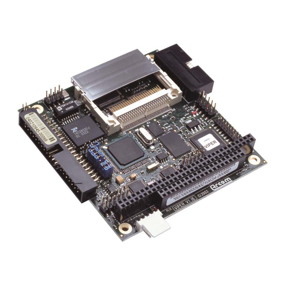
Summary of Contents for Arcom VIPER
- Page 1 VIPER Contents VIPER Intel PXA255 XScale RISC based PC/104 Single Board Computer Technical Manual www.arcom.com...
- Page 2 This product is supplied with a full 3 year warranty. Product warranty covers failure caused by any manufacturing defects. Arcom will make all reasonable effort to repair the product or replace it with an identical variant. Arcom reserves the right to replace the returned product with an alternative variant or an equivalent fit, form and functional product.
-
Page 3: Table Of Contents
VIPER Contents Contents Introduction ............................4 VIPER ‘at a glance’ ........................5 VIPER features ........................6 VIPER support products ......................8 Handling your board safely ....................9 Conventions .........................10 Getting started ..........................11 Using the VIPER ........................11 Detailed Hardware Description ......................13 VIPER block diagram......................13 VIPER address map ......................14 Translations made by the MMU ...................15... -
Page 4: Introduction
Introduction Introduction The VIPER is an ultra low power PC/104 compatible single board computer based on the Intel 400MHz PXA255 XScale processor. The PXA255 is an implementation of the Intel XScale micro architecture combined with a comprehensive set of integrated peripherals including, a flat panel graphics controller, DMA controller, interrupt controller, real time clock and multiple serial ports. -
Page 5: Viper 'At A Glance
VIPER Introduction VIPER ‘at a glance’ Jumpers Five Serial Ports 10/100BaseTX Ethernet Audio – In/Out/MIC/AMP Ethernet LEDs Power (inc battery input) Intel PXA255 XScale 400MHz processor 8/16-bit PC/104 interface JTAG Intel StrataFLASH Digital I/O CompactFLASH (CF+) TFT/STN panel © 2004 Arcom... -
Page 6: Viper Features
VIPER Introduction VIPER features Microprocessor • Intel XScale PXA255 400MHz RISC processor Cache • 32K data cache, 32K instruction cache, 2K mini data cache System memory • Up to 64MByte un-buffered 3.3V SDRAM Silicon disk • Up to 32MByte Intel Strata FLASH (with FLASH access LED) •... - Page 7 • Typically 2W from a single 5V supply • Power Management features allowing current requirements to be as low as 107mA ±5mA (535mW ±25mW). Size • PC/104 compatible footprint 3.8” x 3.6” (96mm x 91mm) © 2004 Arcom Issue H...
-
Page 8: Viper Support Products
• VIPER-UPS (Uninterruptible Power Supply) The VIPER-UPS serves as a 5V DC power supply and battery back up system for the VIPER. The UPS accepts between 10 – 36 VDC (10-25VAC) input and generates the +5V supply for the VIPER. In addition to this, it includes an intelligent battery charger/switch capable of using either the onboard 500mAHr NiMH battery or an external sealed lead acid rechargeable battery. -
Page 9: Handling Your Board Safely
This includes storing the board in appropriate anti-static packaging and wearing a wrist strap when handling the board. Packaging Please ensure that should a board need to be returned to Arcom, it is adequately packed, preferably in the original packing material. Electromagnetic compatibility (EMC) -
Page 10: Conventions
With tables such as that shown below, the white cells show information relevant to the subject being discussed. Grey cells are not relevant in the current context. Byte lane Most Significant Byte Least Significant Byte 15 14 13 12 Field RETRIG AUTO_ R_DIS Reset Relevant information © 2004 Arcom Issue H... -
Page 11: Getting Started
Please read the relevant manual and follow the steps defining the set- up of the board. Once you have completed this task you will have a working VIPER system and can start adding further peripherals enabling development to begin. - Page 12 Contact details are provided in Appendix A – Contacting Arcom, page 72. In order to use a PC/104 board with the VIPER it should be plugged into PL11 for 8-bit cards and PL11/PL12 for 8/16-bit cards. See the sections PC/104 interface...
-
Page 13: Detailed Hardware Description
Detailed hardware description The following section provides a detailed description of the functions provided by the VIPER. This information may be required during development after you have started adding extra peripherals or are starting to use some of the embedded features. -
Page 14: Viper Address Map
VIPER Detailed hardware description VIPER address map PXA255 chip Bus/register select Physical address width Description 0xA4000000 – 0xFFFFFFFF Reserved SDCS0 0xA0000000 – 0xA3FFFFFC 32-bit SDRAM, IC2&3 0x4C000000 – 0x9FFFFFFF Reserved 0x48000000 – 0x4BFFFFFF 32-bit Memory Control Registers 0x44000000 – 0x47FFFFFF... -
Page 15: Translations Made By The Mmu
Translations made by the MMU For details of translations made by the MMU by Redboot for embedded Linux, please refer to VIPER embedded Linux Quickstart Manual. For details of translations made by the MMU by Redboot for VxWorks, please refer to VIPER VxWorks Quickstart and Technical Manual For details of translations made by the MMU for Windows CE .NET, please check the... -
Page 16: Pxa255 Processor
Please refer to the relevant operating system technical manual to select an alternative operating frequency. The processor has two supply inputs: I/O and core generated on the VIPER from the main +5V supply input. The I/O supply is powered from +3.3V, and the core is powered from a +1.06 to +1.3V adjustable supply. -
Page 17: Pxa255 Gpio Pin Assignments
Processor power Voltage DAC Clock management (page 55) SHDN Output High COM 1, 2, 3 & 4 UART Shutdown UART power management (page 57) EN1# Output Low COM 1, 2, 3 & 4 UART Enable © 2004 Arcom Issue H... - Page 18 STATUS Status, (page 25) and FLASH Ready / nBusy memory/silicon disk (page Output Low Hi-Z Chip Select 1 VIPER address map (page 14) PWM0 Output See Backlight Brightness LCD backlight brightness inverter On/Off or variable if control (page 32) datasheet...
- Page 19 Hi-Z Socket 0 & 1 High Byte Enable CB_PKTSEL Output NA PSKTSEL 0 = Socket 0 Select / 1 = Socket 1 Select CB_PREG Output Low PREG CB_PWAIT Input Input PWAIT CB_PIOIS16 Input Input IOIS16 © 2004 Arcom Issue H...
- Page 20 LCD Pixel Clock (STN) / Clock (TFT) LCD_BIAS Output NA LCD Bias (STN) / Date Enable (TFT) ETHERCS2 Output Low Hi-Z Chip Select 2 VIPER address map (page USBCS Output Low Hi-Z Chip Select 3 ETHERCS1 Output Low Hi-Z Chip Select 4...
-
Page 21: Real Time Clock
Detailed hardware description Real Time Clock There are two RTCs on the VIPER: Under embedded Linux and VxWorks the internal RTC of the PXA255 should only be used for power management events, and an external Dallas DS1307 RTC should be used to keep the time and date. Under Windows CE .NET the time and date stamps are copied from the external RTC to the... -
Page 22: Watchdog Timer
When a timeout occurs the board is reset. On reset the watchdog timer is disabled until enabled again by software. For further details see the Arcom operating system Technical Manual and the Intel PXA255 developer’s manual on the Development Kit CD. -
Page 23: Memory
FLASH access LED illuminates. FLASH memory/silicon disk The VIPER supports 16MBytes or 32MBytes of Intel StrataFLASH memory for the OS and application images. The FLASH memory is arranged as 64Mbit x 16-bits (16MByte device) or as 128Mbit x 16-bits (32MByte device) respectively. - Page 24 Don’t Care SRAM Data The data in the SRAM can be made non-volatile by fitting an external battery to power the device in the event of power loss on the main VIPER 5V supply. See the section Battery backup page for details.
-
Page 25: Interrupt Assignments
Active GPIO0 Ethernet GPIO1 PC/104 interrupt controller PC/104 interrupts, page GPIO2 GPIO3 COM5 GPIO4 COM4 GPIO8 CompactFLASH RDY/nBSY Ready = , Busy = GPIO14 FLASH (OS) Ready = , Busy = GPIO32 CompactFLASH card detect © 2004 Arcom Issue H... - Page 26 Reset Address 0x14100000 PC/104 interrupts IRQ9, IRQ14 and IRQ15 are not used by the VIPER, please use an alternate interrupt source from the table above. The ICR Register located at offset 0x100002 from CS5 (0x14000000) must be set-up correctly for the OS running. The PC/104 interrupts are signaled and handled slightly differently between embedded Linux / VxWorks and Windows CE .NET.
- Page 27 Level on IRQ7 on IRQ7 on IRQ5 on IRQ12 on IRQ7 serviced Time Once the VIPER microprocessor has serviced a PC/104 interrupt, clear the corresponding bit in the PC104I register by writing ‘1’ to it. © 2004 Arcom Issue H...
- Page 28 Set RETRIG bit in ICR are no (IRQ service register to ‘1’ to retrigger register to ‘1’ to retrigger outstanding routine started) interrupt on GPIO1 if there interrupt on GPIO1 if there are any outstanding are any outstanding Time © 2004 Arcom Issue H...
-
Page 29: Flat Panel Display Support
The flat panel data and control signals are routed to PL3. See the section PL3 – LCD connector, page 62, for pin assignment and part number details. The VIPER-FPIF1 allows the user to easily wire-up a new panel using pin and crimp style connectors. Contact Arcom (see Appendix A – Contacting Arcom, page 72) for purchasing information. - Page 30 5 bits of red, 6 bits of green, and 5 bits of blue, since the human eye can distinguish more shades of green than of red or blue. STN panel data bit mapping to the VIPER Panel data bus Bit...
- Page 31 DE (Data Enable) Bias The display signals are +3.3V compatible; the VIPER contains power control circuitry for the flat panel logic supply and backlight supply. The flat panel logic is supplied with a switched 3.3V (default) or 5V supply while the backlight is supplied with a switched 5V supply for the inverter.
- Page 32 Function 2). STN BIAS voltage The VIPER provides a negative and a positive bias voltage for STN type displays. The negative and positive bias voltages are set to –22V and +22.5V respectively. Pin connections for these can be found in the section PL3 –...
- Page 33 VIPER Detailed hardware description VIPER-FPIF1 details The VIPER-FPIF1 allows easy connection between the VIPER and a TFT or STN LCD flat panel display. The connectors on the following pages are shown in the same orientation as the picture above. Connector...
- Page 34 LK1 – TFT Clock Delay Selection It has been found that some TFT displays require a delay on the clock, if this is required fit the jumper in position A, if not then fit in position B. PL1 – VIPER LCD cable connector Connector: Oupiin 3215-40GSB, 40-way, 1.27mm (0.05”) x 2.54mm (0.1”) straight-...
- Page 35 PL2, a wide range of LCD displays can be connected with a custom cable.) Signal Name Signal Name BLUE_DATA0 BLUE_DATA1 BLUE_DATA2 BLUE_DATA3 BLUE_DATA4 GREEN_DATA0 GREEN_DATA1 GREEN_DATA2 GREEN_DATA3 GREEN_DATA4 GREEN_DATA5 RED_DATA0 RED_DATA1 RED_DATA2 RED_DATA3 RED_DATA4 PCLK LCDSAFE LCDSAFE LCLK FCLK BKLSAFE LBIAS BKLEN# © 2004 Arcom Issue H...
- Page 36 PL3 – Direct connection to a NEC NL3224BC35-20 5.5inch 320x240 TFT display Connector: Oupiin 2345-33TD2. Mating Cable: Eunsung 0.5x33x190xAx0.035x0.3x5x5x10x10. Signal Name Signal Name PCLK GREEN_DATA5 LCLK FCLK FCLK BLUE_DATA0 BLUE_DATA1 BLUE_DATA2 RED_DATA0 BLUE_DATA3 RED_DATA1 BLUE_DATA4 RED_DATA2 RED_DATA3 LBIAS RED_DATA4 LCDSAFE LCDSAFE GREEN_DATA0 GREEN_DATA1 GREEN_DATA2 GREEN_DATA3 GREEN_DATA4 © 2004 Arcom Issue H...
- Page 37 Detailed hardware description PL4 – Backlight inverter connector Connector: Framatome 76384-407. Mating Connector: Framatome 65240-007. Signal Name PWM0 BKLEN# BKLSAFE BKLSAFE PL5 – STN Bias connector Connector: Framatome 76384-404. Mating Connector: Framatome 65240-004. Signal Name NEGBIAS POSBIAS © 2004 Arcom Issue H...
-
Page 38: Audio
Audio A National Semiconductor LM4548A AC’97 audio CODEC is used to support the audio features of the VIPER. Audio inputs supported by the LM4548A are stereo line in and a mono microphone input. The LM4548A provides a stereo line out that can also be amplified by a National Semiconductor LM4880 250mW per channel power amplifier, suitable for driving an 8Ω... -
Page 39: General Purpose I/O
Eight general-purpose input lines and eight general-purpose output lines are provided on connector PL9. To read from IN[0:7], read the least significant byte from offset 0x500000 of CS5 (0x14500000) to sample the 8 inputs from PL9. VIPER Inputs PXA255 data 3.3V ohms... - Page 40 The general-purpose inputs are 5V tolerant, and the outputs can sink and source up to 24mA @ 3.3V. OUT0B is an inverted OUT0 signal, and is driven to 5V, which provides compatibility with the VIPER-UPS. © 2004 Arcom Issue H...
- Page 41 VIPER Detailed hardware description The following general purpose IO lines are used by the VIPER-UPS: Function External Power Fail Battery Low UPS Power down OUT0B © 2004 Arcom Issue H...
-
Page 42: Usb Interface
VIPER Detailed hardware description USB interface There are two USB interfaces on the VIPER. These interfaces have been designed to support the Open Host Controller Interface (OpenHCI). There are four signal lines associated with each USB channel: • VBUS •... -
Page 43: 10/100Basetx Ethernet
Tx or Rx activity. Ethernet breakout board Arcom can provide an Ethernet breakout board with an RJ45 connector to interface to the VIPER Ethernet connectors PL1 and PL2. The Ethernet breakout board features brackets for panel mounting ease. - Page 44 RJ-2 RJ-2 RJ-2 RJ-1 RJ-1 RJ-1 LANGND RJ-1 LANGND Ethernet LED signal mapping between VIPER and Ethernet breakout connectors Ethernet breakout PL2 – VIPER PL2 – Ethernet status 1x 4-way header LED's connector Signal Name Signal Name LINK LED+ 3.3V...
-
Page 45: Serial Coms Ports
Serial COMs ports There are five high-speed, fully functionally compatible 16550 serial UARTs on the VIPER. Four of these channels can be used as standard RS232 serial interfaces, and the remaining one (COM5) can be configured as RS422 or RS485. - Page 46 When the RTS line is at logic ‘0’ the driver is on. Any data that is transmitted from the VIPER is automatically echoed back to the receiver. This enables the serial communications software to detect that all data has been sent and disable the transmitter when required.
- Page 47 Number of Wires Number of Wires Transmitters Enabled always Transmitters Enabled active RTS Transmitters Enabled active RTS Receivers Enabled always Receivers Enabled always Receivers Enabled always Duplex Mode full Duplex Mode full Duplex Mode half © 2004 Arcom Issue H...
-
Page 48: Pc/104 Interface
The VIPER provides +5V to a PC/104 add-on-board via the PL11 and PL12 connectors. If a PC/104 add-on-board requires a +12V supply, then +12V must be supplied to the VIPER power connector PL16 pin 4. If –12V or –5V are required, these must be supplied directly to the PC/104 add-on board. -
Page 49: Jtag And Debug Access
PXA255 processor on the VIPER. There are many other debug tools that can be interfaced to the VIPER for access to the JTAG Interface of the Intel XScale PXA255 processor. The tables below detail the pins connections between the VIPER and Majic... - Page 50 The Majic probe supports industry-standard debugger APIs, such GNU gdb for Linux Microsoft Platform Builder for Windows CE .NET, which allows you to choose the EPI debugger or a wide variety of other third party debuggers. © 2004 Arcom Issue H...
-
Page 51: Power And Power Management
The power connector PL16 has a +12V connection defined, but is not required for the VIPER under normal operation. It can be used to supply +12V to the PC/104 stack if required. For details of the power connector please see the section PL16 –... -
Page 52: Power Management
Power management The VIPER board supports various power management functions. Under normal conditions the VIPER consumes typically 405mA ±5mA (2025mW ±25mW) once it has finished booting. During the boot process the VIPER consumes up to 470mA, 2350mW. This is with: •... - Page 53 LCD and backlight on 3250 NL3224BC35-20 Inverter (as used + 55PW131 with VIPER-ICE) LCD on and backlight off 1455 For devices using the 3.3V supply from the CompactFLASH socket and FPD logic supply, use 92% as the regulator efficiency. © 2004 Arcom...
- Page 54 VIPER Power and power management Power estimate examples Example 1: VIPER in standby (microprocessor in sleep mode and every power saving option enabled) In this case, the power consumed by the respective categories is: • VIPER current (norm) = 405mA ±5mA •...
- Page 55 When the microprocessor is in sleep mode, the CPU core voltage is shutdown. To communicate with the VCORE DAC, use the following pins to emulate the LTC1659 interface: GPIO LTC1659 DAC pin Function GPIO6 Data GPIO11 Clock GPIO19 Chip Select © 2004 Arcom Issue H...
- Page 56 No auto clear interrupt / toggle GPIO1 on new interrupt AUTO_CLR Auto clear interrupt / low pulse for 1.12µS on GPIO1 on new interrupt Keep set as 0 under normal operating conditions. R_DIS 3 - 7 No function © 2004 Arcom Issue H...
- Page 57 GPIO12 and GPIO13 on the PXA255 can be used to power down the RS232 drivers on the VIPER, to save power. The following table shows the affect of GPIO12 and GPIO13 on the RS232 drivers. Placing the drivers in shutdown mode can reduce the power consumption of the VIPER by up to 57mA (285mW).
- Page 58 The USB Host controller supports a USB suspend state. Placing the controller into the USB suspend state can reduce the power consumption of the VIPER by up to 21mA (105mW). To suspend the USB, the software must write to the relevant bits in the HcControl Register (81h).
-
Page 59: Connectors, Leds And Jumpers
The following diagram shows the location of the connectors, LEDs and jumpers on the VIPER: PL17 & LK1 PL16 PL11 & PL12 PL10 Flash Access The connectors on the following pages are shown in the same orientation as the picture above, unless otherwise stated. © 2004 Arcom Issue H... -
Page 60: Connectors
VIPER Connectors, LEDs and jumpers Connectors There are 12 connectors on the VIPER for accessing external devices. Connector Function Connector Details in Section 10/100BaseTX Ethernet PL1 – 10/100BaseTX Ethernet connector, interface page Ethernet controller status PL2 – Ethernet status LED's connector, page LED’s... - Page 61 PL2 – Ethernet status LED's connector Connector: Molex 87089-0616, 6-way, 2mm (0.079”) x 2mm (0.079”) pin header. Mating connector: Molex 51110-0650. Mating connector crimps (x6): Molex 50394-8100. Signal Name Signal Name 3.3V Link 3.3V Activity © 2004 Arcom Issue H...
- Page 62 BLKEN# BLKSAFE NEGBIAS LCDSAFE GPIO16/PWM0 8 POSBIAS FPD0 FPD1 FPD2 FPD3 FPD4 FPD5 FPD6 FPD7 FPD8 FPD9 As viewed from the connector pins FPD10 FPD11 FPD12 FPD13 FPD14 FPD15 FCLK BIAS / DE PCLK LCLK © 2004 Arcom Issue H...
- Page 63 Framatome 71600-040. Signal Name Signal Name TX5+ (RS422) TX5- (RS422) (TX5+/RX5+ RS485) (TX5-/RX5- RS485) RX5+ (RS422) RX5- (RS422) RTS2 CTS2 DCD4 DSR4 RTS4 CTS4 DTR4 DCD1 DSR1 RTS1 CTS1 DTR1 As viewed from the connector pins © 2004 Arcom Issue H...
- Page 64 Connectors, LEDs and jumpers PL5 – CompactFLASH connector Connector: 3M N7E50-A516HE-50, 50-way CompactFLASH Type II Connector. Signal Name Signal Name /CD1 /CE2 /CE1 /VS1 (GND) /IORD /IOWR RDY/BSY +3.3V +3.3V /RESET WAIT /INPACK (NU) /REG /IOCS16 /CD2 © 2004 Arcom Issue H...
- Page 65 PL7 – USB connector Connector: Oupiin 2015-2 X 5 G D, 10-way, 2.54mm (0.1”) x 2.54mm (0.1”) dual row header. Mating connector: Framatome 71600-010. Signal Name Signal Name VBUS-1 VBUS-2 DNEG-1 DNEG-2 DPOS-1 DPOS-2 SHIELD SHIELD © 2004 Arcom Issue H...
- Page 66 OUT4 OUT5 OUT6 OUT7 PL10 – JTAG connector Connector: Oupiin 2015-2 X 5 G D, 10-way, 2.54mm (0.1”) x 2.54mm (0.1”) dual row header. Mating connector: Framatome 71600-010. Signal Name Signal Name VCC3 nTRST TCLK © 2004 Arcom Issue H...
- Page 67 24 A7 IRQ4 16 +5V 25 A6 IRQ3 17 NC (Master) D14 26 A5 NU (DACK2) 18 GND 27 A4 NU (TC) 19 GND 28 A3 BALE 29 A2 30 A1 31 A0 32 GND © 2004 Arcom Issue H...
- Page 68 VBAT provides connections for a battery backup supply for the 256KByte static RAM and the Dallas DS1307 64 x 8 Serial Real-Time Clock. +12V connection defined, but is not required for the VIPER under normal operation. It can be used to supply +12V to the PC/104 stack if required.
-
Page 69: Status Led's
VIPER Connectors, LEDs and jumpers Status LED’s There is a single status LED on the VIPER, which indicates FLASH access to the bootloader FLASH or the main FLASH memory / Silicon Disk. © 2004 Arcom Issue H... -
Page 70: Jumpers
VIPER Connectors, LEDs and jumpers Jumpers There are seven user selectable jumpers on the VIPER, their use is explained below. Default settings The default positions of the jumpers is as follows: PL17 PL17 Rotate this diagram 90 clockwise to match the VIPER picture on page 59. - Page 71 Default setting: (120Ω) connected. RS422 RX line termination resistor (120Ω) disconnected. LK6 & LK7 Description RS485 half-duplex. Default setting: RS422 full-duplex. Only fit LK4 and LK5 if the VIPER is at the end of the network. © 2004 Arcom Issue H...
-
Page 72: Appendix A - Contacting Arcom
Appendix A – Contacting Arcom Appendix A – Contacting Arcom Arcom sales Arcom’s sales team is always available to assist you in choosing the board that best meets your requirements. Contact your local sales office or hotline. Sales office US... -
Page 73: Appendix B - Specification
107mA ±5mA (535mW ±25mW) in standby mode. Battery Input 2.7v to 3.3v (external). Typical discharge 2µA. Dimensions PC/104 compatible format. 3.775” x 3.550”. 96mm x 91mm. Weight 96 grams. MTBF 90,000 hours based on MIL-HDBK-217F using generic failure rates. © 2004 Arcom Issue H... -
Page 74: Appendix C - Mechanical Diagram
0.00 0.00 PL16 When mounting the VIPER use only M3 (metric) or 4-40 (US) screws. The mounting pad is 6.35mm, 0.25” and the hole is 3.175mm, 0.125”, so ensure any washers fitted are smaller than the pad. Using oversized screws and washers, or tooth locking washers, can cause short circuits and over-voltage conditions. -
Page 75: Appendix D - Reference Information
Intel XScale™ PXA255 processor documentation www.intel.com http://www.intel.com/design/pca/prodbref/252780.htm Standard Microsystems Corporation SMSC SMC91C111 Ethernet Controller documentation www.smsc.com Exar Corporation Exar XR16C2852 DUART with 128Byte FIFO documentation www.exar.com National Semiconductor Corporation National Semiconductor LM4548A AC’97 Codec documentation http://www.national.com © 2004 Arcom Issue H... - Page 76 Koninklijke Philips Electronics N.V. Philips LM4548A AC’97 Codec documentation http://www.philips.com Maxim Integrated Products Inc. Maxim DS1307 64 x 8 Serial Real Time Clock documentation http://www.maxim-ic.com Linear Technology Corporation. Linear Technology LTC1659 Micropower DAC documentation http://www.linear.com/ © 2004 Arcom Issue H...
-
Page 77: Appendix E - Acronyms And Abbreviations
Thin Film Transistor, a type of LCD flat-panel display screen UART Universal Asynchronous Receiver / Transmitter Uninterruptible Power Supply Universal Serial Bus Voltage Alternating Current Voltage Direct Current Video Graphics Adapter, display resolution 640 x 480 pixels V IPER-ICE VIPER-Industrial Compact Enclosure © 2004 Arcom Issue H... -
Page 78: Index
· 53 CODEC · 6 interrupt · 25 COM · 5 ports connector · 63 COM1 · 45 COM2 · 45 features · 6 COM3 · 46 FIFO · 6 COM4 · 46 FLASH · 6 © 2004 Arcom Issue H... - Page 79 · 51, 68 LK4 · 71 ethernet · 57 LK5 · 71 external device · 53 LK6 · 71 processor · 52, 55 LK7 · 71 supply · 51 UART · 57 USB · 58 © 2004 Arcom Issue H...
- Page 80 · 22 static RAM · 24 weight · 73 status LED · 69 Windows CE · 73 STN · 5, 30, 33 PC/104 · 28 bias connector · 37 StrataFLASH · 5 support · 8 © 2004 Arcom Issue H...
Need help?
Do you have a question about the VIPER and is the answer not in the manual?
Questions and answers