Advertisement
Advertisement
Table of Contents

Subscribe to Our Youtube Channel
Related Manuals for q-Tech QP031


Summary of Contents for q-Tech QP031
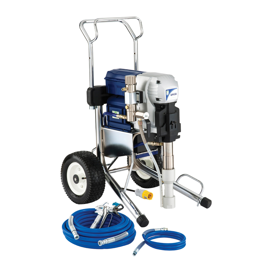
- Page 1 QP031 QP036...
- Page 2 QP036 QP031 Model Brushless Brushless Motor Type 1800W Mode Model 1500W Mode Model Power input 1800W 1500W Voltage See machine nameplate Max Tip Size 0.035 in. 0.031 in. Max Flow 5.3 l/min (1.4 gpm) 4.17 l/min (1.1 gpm) Max Pressure...
- Page 3 GENERAL SAFETY RULES Grounded tools must be plugged into an outlet properly installed and grounded in WARNING! Read and understand accordance with all codes and ordinances. all instructions. Failure to follow all Never remove the grounding prong or modify the plug in any way. Do not use instructions listed below may result in electric any adaptor plugs.
- Page 4 Personal Safety g) If devices are provided for the connection of dust extraction and collection facilities, a) Stay alert, watch what you are doing and ensure these are connected and properly use common sense when operating a power used. Use of these devices can reduce dust- tool.
- Page 5 f)Keep cutting tools sharp and clean. SPECIFIC SAFETY RULES Properly maintained cutting tools with sharp WARNING: HIGH PRESSURE. Never leave cutting edges are less likely to bind and are pressurized system unattended. Always easier to control. f o l l o w t h e P r e s s u r e R e l i e f P r o c e d u r e . g)Use the power tool, accessories and Take precautions to avoid high pressure tool bits etc., in accordance with these...
- Page 6 Contact with aluminum parts may cause an will penetrate through these materials & explosion. into the hand. • NEVER try to stop or deflect leaks with Some of the most common of these solvents are: Carbontetrachloride, Chlorobenzene, your hand or body. •...
- Page 7 ALWAYS INSPECT SPRAYING AREA and helps prevent accidentally placing your fingers or any part of your body • Keep the spraying area free from close to the spray tip. obstructions. SPRAY TIP SAFETY • Make sure the spraying area has good ventilation to safely remove vapors and mists.
- Page 8 allow high pressure spray to be emitted detailed instructions on how to ground, from the coupling and result in an check your local electrical code. • ALWAYS ensure switch is in OFF position injection injury or serious bodily injury. • Only use hoses with a spring guard.
-
Page 9: Electrical Connection
FLUSHING SAFETY • NEVER use cleaning solvents with flash points below 140 degrees F. Some of WHEN SPRAYING & CLEANING WITH these are: acetone, benzene, ether, FLAMMABLE PAINTS AND THINNERS gasoline, naptha. Consult your supplier to be sure. When spraying with flammable liquids, the unit must be located a minimum of ASSEMBLY 25 feet away from the spraying area in... -
Page 10: Operation
Grounding Instructions cause a drop in line voltage resulting in loss This product must be grounded. In the event of power and overheating. a 12 gauge of an electrical short circuit, grounding cord is recommended. If an extension cord r e d u c e s t h e r i s k o f e l e c t r i c s h o c k b y is to be used outdoors, it must be marked providing an escape wire for the electric with the suffix W-A after the cord type... - Page 11 Lubricate the packings: Fill the packing nut/ When changing between water-based wet cup with about 2-3 drops of throat seal and oil-based materials. First flush with oil. clear water, then flush with mineral spirits. When changing colors. Flush with a compatible solvent, such as water or mineral spirits as needed.
- Page 12 splashback hazard. Turn the unit on. Turn the pressure control knob clockwise 11. Then turn the unit off and turn the to increase the pressure just enough to let the pump run. pressure control knob anticlockwise Allow the pump to run and watch back to the minimum setting.
- Page 13 unlock the trigger and hold the trigger snapped in place on the seat and insert open. Then close the priming valve. the seat into the tip guard. Make sure Keep the trigger held open and allow that it is aligned to the circular opening the pump to run and watch the fluid in the tip guard.
- Page 14 PRESSURE RELIEF PROCEDURE. Whenever you stop spraying, even for a short break, follow the "Pressure Relief Procedure". Priming Valve IMPORTANT! To avoid possible serious body injury, always follow this procedure whenever the sprayer is shut off, when WARNING: If the SPRAY TIP OR HOSE checking it, when installing, changing or IS CLOGGED, Expect material splashing cleaning tips, when adding material and...
- Page 15 bounce-back of the material and a rough Then paint flat areas. finish. Do not allow the material to run out. Remember to follow the PRESSURE RELIEF PROCEDURE before refilling material. If ALL MODELS the material does run out, the pump will suck in air.
- Page 16 CLOGGED FLAT TIP rate of the spray gun movement, and distance to surface.) If you are using a flat tip and the spray tip The numbers on the tip identify its orifice size becomes clogged, relieve pressure from and fan width. The first number on the tip hose by following the "PRESSURE RELIEF identifies the fan width radius in inches.
- Page 17 always strain paint before use with a paint water-based materials), mineral spirits strainer bag and regularly clean all filters (for oil-based materials) or lacquer and strainers. thinner ( for lacquers). Special flushing fluids may be required for component R e p l a c e t i p s b e f o r e t h e y b e c o m e...
- Page 18 minimum position and turn the unit on. empty.) 16. Clean the inlet strainer or hopper With the trigger held open, slowly turn the pressure knob clockwise to increase strainer. Remove and clean it with a soft the pressure just enough to let the brush in the appropriate solvent and pump run.
-
Page 19: Daily Maintenance
20. If flushing was with water, flush again and perform the following: with mineral spirits to prevent corrosion • Add about 2 drops of throat Seal Oil to inside the pump. lubricate the packings. CAUTION: Never leave water in the pump for •... -
Page 20: Pump Packings
and tighten the packing nut. Replace pickup tube (3) from the bottom of the fence. pump. At the same time remove the inlet ball seat disc (5), o-ring (6), check CAUTION: The packing nut should be ball (7) and ball guide (8) tightened just enough to stop leakage Lay the machine on its back and only, but not any tighter. -
Page 21: Motor Maintenance
MOTOR MAINTENANCE Loosen the Packing nut (24) from Pump Housing(19). LUBRICATION – The gear case grease may Pull the Displacement Piston (17) out from Pump Housing (19). be changed every 200 hours of operation. Remove the Packing set seat (22), This is best entrusted to a qualified repair release I ntake di sc sea t ( 08) a nd technician. -
Page 22: Troubleshooting
Troubleshooting Problem: Motor will not run Check Solution Electrical supply- must match voltage Use correct outlet on machine nameplate Extension cord-check continuity Replace extension Power supply cable-check continuity Replace cable Carbon brushes Replace brushes Bad switch Replace switch Motor damage Replace or repair motor Problem: Pump loses prime or will not prime Check... - Page 23 LCD screen error codes: Check Solution Check if Pressure transducer and LCD disconnected display are disconnected material shortage Fill material again Overload (must be replaced by Check Motor or Pressure transducer the service organization.) Maximum pressure exceeded Check Pressure transducer...
- Page 24 WIRING...
- Page 26 EXPLODED VIEW (QP031,QP036) NO.01~126V1.0...
- Page 27 PARTS LIST (QP031,QP036) Q'TY Item Q-Tech Part No. Description QP031 QP036 QP031-1A SUCTION TUBE 4 -160L QP036-1A SUCTION TUBE 4 -105L QP031-1B SUCTION TUBE 10 -160L QP036-1B SUCTION TUBE 10 -105L QP036-02 GLAND NUT QP036-03 O-RING Ø39.3xØ45.1x2.8 QP036-04 INTAKE DISC...
- Page 28 Q'TY Item Q-Tech Part No. Description QP031 QP036 QP036-39 SCREW M5 x 15 QP036-40 Ø1.5 x Ø44 x Ø47 RETAINING RING QP036-41 DRIVE PISTON QP036-42 Ø12 x 52 PUMP WRIST PIN QP036-43 Ø20 x 42 DRIVE WRIST PIN QP036-44 CONNECTING ROD...
- Page 29 Q'TY Item Q-Tech Part No. Description QP031 QP036 QP036-82 DUAL PURPOSE WRENCH Q400-005 LUBRICATING OIL TANK 100 cc QP036-84 QP036-85 SPRING WASHER QP031-86 MOTOR UNIT QP036-86 MOTOR UNIT 2.5HP QP036-87 SCREW M10 x 20 QP036-88 SCREW M10 x 25 QP036-89...
- Page 30 London Dublin Aristospray UK, Granville House Aristospray Wallingford Road, Uxbridge 2b Stephenstown Industrial Middlesex UB8 2RW Park, Balbriggan, Co. Dublin Tel: 00353 1690 3162 Fax: 00353 1690 3480 www.edx-tools.co.uk E:sales@aristospray.com...
Need help?
Do you have a question about the QP031 and is the answer not in the manual?
Questions and answers