Table of Contents
Advertisement
DriveCam Installation
DriveCam Standard Installation
Installing the DriveCam
Power Cable. This is the most basic installation type, connecting the VER with no
additional components.
Start Here ............................... 3
Mounting Information ................. 4
Electrical Connections ............... 6
VER Testing Procedures ............ 7
Vehicle to VER Association......... 8
Finishing Up ............................ 8
Additional Information ................ 9
Hardware (provided)
DC3/DC3P Kit
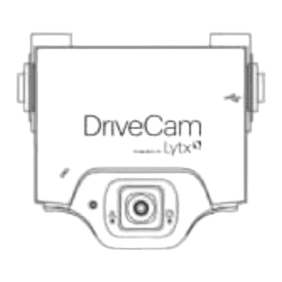
DC3/DC3P Video Event Recorder (VER)
Standard (Windshield) Mounting Bracket
Torx Screws (2); Torx Wrench; Alcohol Wipe
Standard Power Cable Kit
DC3/DC3P Standard Power Cable (14 ft.)
Additional items you may need (not provided)
Felt-tip marker Voltmeter
Wire cutter / crimper
Wire connectors & extra wire (18 gauge)
Flat blade screwdriver or panel removal tool
Installation & How To Guides:
DriveCam Mounting Guidelines (DRC 340)
DriveCam Standard Installation Guide (DRC 303)
DriveCam 5-Port HUB Installation Guide (DRC 304)
DriveCam 5-Port HUB Installation with Universal Module (DRC 305)
Optional DriveCam Components: Remote Pushbutton, External GPS Antenna, Fuel Efficiency Display, Universal Module
(UM05). All connect through the DriveCam 5-Port HUB. Refer to the 5-Port HUB guides for installation instructions.
Order DriveCam Parts & Equipment: http://drivecam.force.com/partsorders
®
DC3/DC3P Video Event Recorder (VER) using the Standard
Available online at:
http://www.drivecam.com/resource-center/installation-how-to-guides
* This Document
Hardware (ordered separately)
Alternate Mounting Brackets
Extended (Bulkhead) Bracket
RAM-Mount (Articulating) Bracket
Contact Lytx for assistance with any issues
related to how or where VERs should be
mounted.
www.lytx.com
Advertisement
Table of Contents

Summary of Contents for DriveCam DC-3000-256-C
-
Page 1: Table Of Contents
DriveCam 5-Port HUB Installation with Universal Module (DRC 305) Optional DriveCam Components: Remote Pushbutton, External GPS Antenna, Fuel Efficiency Display, Universal Module (UM05). All connect through the DriveCam 5-Port HUB. Refer to the 5-Port HUB guides for installation instructions. Order DriveCam Parts & Equipment: http://drivecam.force.com/partsorders... -
Page 2: Safety Information
Some jurisdictions have adopted, or may in the future adopt, laws that prohibit objects from being mounted on a vehicle’s windshield. For example, California, Minnesota, New Jersey and Florida currently prohibit or limit the mounting of objects, including DriveCam event recorders, on windshields. You are responsible for complying with any such laws, and DriveCam does not accept responsibility for your failure to do so. -
Page 3: Start Here
Torx screw and power connection. Mounting Options: Refer to the DriveCam Mounting Guidelines (DRC 340) if you’re installing in a vehicle without a standard rear view mirror. The document provides additional details and diagrams about VER mounting in various vehicle types, including instructions for using the Extended (Bulkhead) Bracket and RAM-Mount (Articulating) Bracket. -
Page 4: Mounting Information
DriveCam Installation 3. Mark the mounting location on the glass CAUTION: Do not peel the backing from the adhesive strips until the next step. A) Hold the assembly in place and trace the outline of the bracket on the windshield with a marker. - Page 5 DriveCam Installation 5. Mount the VER in the bracket A) Plug the DC3/DC3P Power Cable (14 ft.) into the VER. B) Place the VER in the bracket. C) Adjust the VER so that it hangs vertically (plumb). D) Secure the VER in the bracket using the two Torx screws and Torx wrench (provided).
-
Page 6: Electrical Connections
DriveCam Installation 7. Electrical connections The black, red and brown wires are the three required connections for the VER to function. The red wire provides primary power and must be connected to a continuous power source. The brown wire is an ignition-sense, used by the VER to activate the IR Illuminator (page 8) when the vehicle ignition is switched on. -
Page 7: Ver Testing Procedures
DriveCam Installation 8. Test the RED WIRE connection (continuous power) Once the power and ground connections are made and the vehicle ignition is switched on, the status light to the right of the interior-facing lens should be lit (either a red or green light). -
Page 8: Vehicle To Ver Association
C) Finalize all electrical connections. Use cable-ties to bundle and secure all wires so they don’t come loose. D) Keep the Torx wrench and this guide in a safe place for future use. The DriveCam-equipped vehicle is ready to be placed in-service with the DriveCam Program. -
Page 9: Additional Information
VER to the HUB and then a separate power cable connects the HUB to vehicle power and ground. All other components (Remote Pushbutton, External GPS Antenna, Fuel Efficiency Display and the Universal Module (UM05)) plug into the 5-Port HUB. At Lytx (formerly DriveCam, Inc.), we harness the power of data to change human behavior and help good companies become ™...


Need help?
Do you have a question about the DC-3000-256-C and is the answer not in the manual?
Questions and answers